US1388198A - Vegetable and fruit dispenser - Google Patents
Vegetable and fruit dispenser Download PDFInfo
- Publication number
- US1388198A US1388198A US455809A US45580921A US1388198A US 1388198 A US1388198 A US 1388198A US 455809 A US455809 A US 455809A US 45580921 A US45580921 A US 45580921A US 1388198 A US1388198 A US 1388198A
- Authority
- US
- United States
- Prior art keywords
- gate
- spout
- articles
- pedal
- container
- Prior art date
- Legal status (The legal status is an assumption and is not a legal conclusion. Google has not performed a legal analysis and makes no representation as to the accuracy of the status listed.)
- Expired - Lifetime
Links
- 235000013311 vegetables Nutrition 0.000 title description 9
- 235000013399 edible fruits Nutrition 0.000 title description 4
- 239000000463 material Substances 0.000 description 7
- 230000000994 depressogenic effect Effects 0.000 description 5
- 238000010276 construction Methods 0.000 description 4
- 239000002184 metal Substances 0.000 description 3
- 235000012055 fruits and vegetables Nutrition 0.000 description 2
- 230000004048 modification Effects 0.000 description 2
- 238000012986 modification Methods 0.000 description 2
- 230000003014 reinforcing effect Effects 0.000 description 2
- 238000005303 weighing Methods 0.000 description 2
- BHMLFPOTZYRDKA-IRXDYDNUSA-N (2s)-2-[(s)-(2-iodophenoxy)-phenylmethyl]morpholine Chemical compound IC1=CC=CC=C1O[C@@H](C=1C=CC=CC=1)[C@H]1OCCNC1 BHMLFPOTZYRDKA-IRXDYDNUSA-N 0.000 description 1
- 244000228957 Ferula foetida Species 0.000 description 1
- PEDCQBHIVMGVHV-UHFFFAOYSA-N Glycerine Chemical compound OCC(O)CO PEDCQBHIVMGVHV-UHFFFAOYSA-N 0.000 description 1
- 241000282898 Sus scrofa Species 0.000 description 1
- 230000009471 action Effects 0.000 description 1
- 230000007812 deficiency Effects 0.000 description 1
- 238000003780 insertion Methods 0.000 description 1
- 230000037431 insertion Effects 0.000 description 1
- 238000007689 inspection Methods 0.000 description 1
- 101150085091 lat-2 gene Proteins 0.000 description 1
- 238000004519 manufacturing process Methods 0.000 description 1
- 230000007246 mechanism Effects 0.000 description 1
- 235000013550 pizza Nutrition 0.000 description 1
- 229920000136 polysorbate Polymers 0.000 description 1
- 230000000284 resting effect Effects 0.000 description 1
- 239000002023 wood Substances 0.000 description 1
Images
Classifications
-
- A—HUMAN NECESSITIES
- A47—FURNITURE; DOMESTIC ARTICLES OR APPLIANCES; COFFEE MILLS; SPICE MILLS; SUCTION CLEANERS IN GENERAL
- A47F—SPECIAL FURNITURE, FITTINGS, OR ACCESSORIES FOR SHOPS, STOREHOUSES, BARS, RESTAURANTS OR THE LIKE; PAYING COUNTERS
- A47F1/00—Racks for dispensing merchandise; Containers for dispensing merchandise
- A47F1/02—Racks for dispensing merchandise; Containers for dispensing merchandise for granulated or powdered materials, i.e. bulk materials
- A47F1/03—Dispensing means, e.g. with buttons or handles
Definitions
- FRANK PHILIPPS a muzen of the United States, residing at Ham-' mond, in the county of Lake and State of Indiana, has invented certain new and useful Improvements in Vegetable and Fruit'Dispensers, of which the following is a specification.
- the present invention relates to store fur-. niture, and particularl to a device .by use ofwhich vegetables, fi'uit and like goods may be quickly and easily dispensed to cus- .tomers.
- An object of the present invention is to provide a device of this character which is not only adapted to use by the salesman for quickly measuring out desired quantities of the customers wait on themselves, as the device provides a read means for supporting a container, means or permitting the fruit or vegetables to be delivered to the container, and means for determining the weight or quantity of the goods deposited in the container. 4
- Another object of the invention is to provide a device of this character which is of relatively compact and strong construction so that it is capable of withstanding considerable wear and hard usage, and a device which may be easily kept in a sanitary condition and to which access may be readily had to the interior thereof for filling the same and for withdrawing its contents.
- a further object of the invention is to provide an improved frame or body construction adapted to support and house in or protect various operating elements, and to support such elements in convenient position of access to the salesman or other party dispensing the goods, and which maintains the parts in close proximity to each other so that they may be quickly and easily operaltedwithout the exercise. of undue care or s ill.
- a still further object ofthe invention is to provide a device which may be operated quickly and easily so as to save considerable time in the handling and weighing of fruit and vegetables, and a device which embodies various novel features which combined, produce a practical and economical dispenser both as to manufacture and use.
- Figure 1 is a front elevation of a vegetable and fruit dispenser constructed according to I the present invention, the device being closed and a container shown as resting on the platform;
- Fig. 2 is a similar view disclosing the dis an open and illustrating the parts of the a device when the latform is depressed or weighted down with the required quantity of the goods;
- Fig, 3 is a side elevation of the device in the position of Fig. 1, parts of the same being shown in section;
- Fig. 4 is a vertical longitudinal section taken substantiall centrally through the device in the position of Fig. 1; 1
- Fig. 5 is a horizontal section taken substantially on the line 5-5 of Fig. 3 and looking downwardly in the direction indicated by the arrows; i
- Fig. 6 is a vertical section the structure illustrated in Fig. 5 on the line 6-6 thereof, and in the direction indicated by the arrows;
- Fig. 7 is a detail plan. view of the underside of the scale platform.
- the body part or frame of the device comprises. a pair of forward uprights or standards 10 and -11, connected together at their upper ends by a front cross piece 12 and reinforced taken through The space between the cross pieces 12 and i 13, and the standards 10 and 11 is preferabl closed inby a transparent panel 14, althoug any other suitable closure may be em loyed.
- the front portion of the frame thus ormed, constitutes a support for a pair of sides.
- Each side is (onstructed of a top rail 15 and a bottom rail 16, the rails supporting a plurality of slats 17 or the like, which extend between the rails and form the body of the side, and permit ins ection of the contents of the body through t e side.
- the top rail 15 is joined to the front section at its upper end while the bottom rail 16 is joined to front section at a point below the cross piece 13.
- the rear end of the platform comprises a pair of standards, which are secured to the rear ends of the top and bottom rails 15 and 16, and which are interbraced by a top brace 19 and a lower or intermediate brace 20.
- the brace 19 is connected to the tops of the standards 18, while the brace 20 preferably lies in the horizontal plane of the side rails 16, and below the forward cross brace 13.
- the rear wall or portion of the structure may also be closed in b slats or bars 21, forming a grating for holc ing the contents in the body and at the same time permitting the inspection of the contents from outside the body.
- a sheet metal bottom 22 is provided.
- the rear end of the bottom 22 is secured by a clamping strip 23 upon the upper face or edge of the rear cross brace 20.
- the lateral marginal edges of the bottom 22 are secured by lateral extensions of the clamping strip 23 to the upper edges or faces of the side rails 16, so as to completely inclose I the lower end of the body.
- the intermediate portion of the sheet metal body 22 is depressed or arched downwardly, and slopes uniformly from the rear cross brace 20 to the forward edge of the bottom 22, which bottom projects forwardly beneath the front cross brace 13 to provide a trough or feeding mouth of a predetermined size downwardly through which the fruit and vegetables may roll when released.
- the forward lower corner of the cross piece 13 is preferably beveled or cut away to provide an inwardly and downwardly sloping face 24, which leads to the troughed bottom 22, to permit viewing of the contents of the trough and also easy access of the hand for picking out one or more of the articles to be dispensed, should it be found necessary to add an additional article for completing the weight.
- This inclined face 2 L also provides a hopper or opening through which articles may be returned to the spout or bottom 22,
- a gate 25 is mounted on the body frame at the forward end of the bottom or spout and is adapted to control the iiow of the articles or material from the spout.
- Th is gate 25 comprises a flat strip or board pivbted at 26 against the forward side offthe upright 10 at one side of the bottom 22 and the strip 25 is adapted to extend in av generalhorizo ntal direction across the front of the body, and is adapted to swing upon its pivot 26 within the limits of a strap or guard 27 which issecured to the opposite front standard or upright 11.
- the guard 27 is preferably of-substantially loop shape with its ends screwed or otherwise secured against the outer face of the upright 11, and the gate or strip 25 is of sufficient length to project from the strap 27 and beyond the outer edge of the upright 11 to form a handle 28 by means of which the gate 25 may swing down into the low fgr end of the strap 27, for closing the gate.
- top of the gate 25 terminates in spaced relation from and also below the plane of the upper portion of the cross brace 13, so that ample space is provided between the top of the gate 25 and the inclined face 2st to receive the hand for withdrawing or replacing articles.
- a pedal or foot lever 29 is provided and is located upon the standard 11 at the side thereof so that the person dispensing the goods may stand at the front of the device and place the right foot on the pedal 29, depress it and thus open the gate 25.
- This pedal 29 is provided with a substantially T-shaped head or shoe 30 upon its inner end, and the shoe or head is confined in a vertical guide 31 which is preferably in the form of a sheet metal strip overturned at its longitudinal edges, and with such edges closely spaced apart to form an undercut T-slot in which the shoe fits with the shank thereof projecting outwardly for supporting the pedal 29.
- the pedal is connected by a flexible cord 32 with the outer or swinging end of the gate 25.
- the guide rail 31 is preferably secured against the outer face of a strip 33 secured upon the inner side of the front post 11, in position to permit the pedal 29 to project laterally beyond the post 11 a distance sufficient to receive the foot of the operator.
- the flexible cord 32 extends upwardly from the pedal 29 and through an opening 34 which is formed through the adjacent side rail 16 and thence upwardly and over a pair of pulleys 85 carried in a suitable block 36 seated in the upper part of the standard 11.
- the flexible cord 32 is trained over these pulleys 35jfind carried downwardly at the forward'side of the standard 11 and connected at its end by a strap 37 to the gate 25 at the inner side of the strap or guard 27.
- the standard 11 is provided at ritsrouter side with a spring-retainer 38,
- the r .ainer 38 is of sullicient strength to support the gate in raised position and the same time permits the r easing oi; the gate when slight p1 brought to bear upon the handle 28 in a diroction to close the gate.
- a supporting plat-form 39 Housed within the forward part of the body or frame of the device a supporting plat-form 39. This platform extends be tween the lower end portions of the stand-- ards and 11 and beneath the forward end. of the bottom or spout 22 so that a basket, such as shown in dotted lines at 40 in Fig.
- Theplatform 39 is sug'ipor d a n the lever mechanism 41 of a scale which is housed in a base ea so cured by straps as or the like to the inner sidesof the uprights .10 and 11 for not only reinforcing the uprights, but also for hour .ing and protecting the scalemechanism.
- the lever 41 is connected by a link 44- to a scale beam 45? of approved construction, which is pivoted. at so to the front side of the top cross brace 12 and in position over the platform 39.
- the scale beam carries the usual adjustable weight 4? and -other purtenances for determining the diii'erent weights it is desired to place upon the platform 39, for supporting a yoke bracket 48 which embraces the outer end of the scale beam 4&5 for igniting the rise and fall oithe same.
- the rams or body part of the dispenser is of such C"El1:l0l2i0ll that it houses and. supports the various parts oi? the dispensingand weighing apparatus,
- Another feature of the device as thus constructed is that while the contents mayiin. bulk be (sickly and easily delivered the basket or other container used 'it admits of the return or of the individual picking out of one or more of the articles according to whether an excess amount has been. delivered or whether the amount falls itly short of the weight desired.
- the person dispensing the goods places cont iner sill on the platform 39.
- the weight a? is then adjusted on the scale beam to the indication opposite the desired weight. This having been done, the person then places the :5 cos the latter action draws into its lhe retainer Y
- the cross brace 12 is also utilized c holds it in such open position so that the operator may release the footn As soon as the quantity-of goods has flowed from the spout 2 2 into the container 40 to an amount sulficient to swing the scale beam 45, the operator then quickly presses down upon the handle 28 ot the to close the latter.
- the device also he used for determining the exact.
- lVhat is claimec is: 1.
- a dispensing cc hollow body adapted to receive articles to hedispensed and provided with a forwardly inclined bottom forming cho i a closing the outer end oithe chute pedal mounted upon the side of the body and connected to the gate for swine the same into openpositionupon de ression of the pedal, and a scale platform'inounted within the forward end of the bodyportion beneath said gate for supporting a container in position to receive articles from the spout.
- an article dispenser a body portion comprising front and rear pairs of uprights, top and intermediate braces arranged between said pairs of uprights for interbracing the same, top'and bottom side rails joining said uprights to provide a hollow body adapted to receive articles to be dispensed, an inclined bottom carried between the 'uprights and said rails and inclined forwardly and downwardly to form a spout adapted to deliver material beneath an intermediate .
- a gate pivoted at one end to one of the forward uprights and the gate extending across the forward end of said bottom to close the spout, a vertically slidable pedal mounted upon the opposite forward upright and having connection with the free end of said gate for swinging the latter upwardly when the pedal is depressed, and a wei hing scale mounted between and supporte from said forward uprights, whereby said scale is protected betweenthe uprights and whereby the platform of the scale may be supported in position to receive a container for articles delivered from the spout.
- a hollow body 40 portion adapted to receive articles in bulk and having a forwardly inclined delivery spout at its forward end, a cross brace in the forward end of said body portion spaced above the bottom of the spout and having, a forwardly and downwardly inolinedfront face providing a passage leading down into the spout, a gate mounted upon the forward end of the body portion and extending across the forward end of the spout in spaced relation to said cross brace to permit insertion and removal of articles through said space into and from the spout, means for swinging the gate into open and closed positions, and a scale platform mounted in the forward end of said body portion beneath said gate. 6.
- a hollow body portion adapted to receive articles in bulk, and provided with a forwardly and downwardly inclined delivery spout, the front wall of said body portion having a lower cross brace spaced above said spout to permit a passage beneath the cross brace through which the articles are adapted to flow in a restricted stream, a gate pivotizlly mounted upon the forward end of the body portion and adapted to extend across the forward end of said spout to check the flow of articles therefrom, said ate being spaced forwardly from said cross race whereby to provide between the gate and the cross brace a passage by means of which access may be readily gained to the spout when the gate is closed for removing articles from the spout and for replacing'the articles therein, and a support carried in the forward end of the "i5 body portion beneath the open end of the spout for maintaining a container in proper position for receiving the bulk of material h n the gate is vOIpBR I-U T PHILIPPS
Landscapes
- Details Of Rigid Or Semi-Rigid Containers (AREA)
Description
F. PHILIPPS.
VEGETABLE AND FRUIT DISPENSER.
APPLICATION FILED MAR. 26, I921.
1,388,198. A Patented Aug. 23, 1921.
2 SHEETS-SHEET 1.
APPLICATION FILED MAR. 26, 1921- F. PHILIPPS.
VEGETABLE AND FRUIT DISPENSER.
1,388,198. Patented Aug. 23, 1921 2 SHEETS-SHEET 2- 12 '15 10 1 F 14 I3 ZZ 24 zz 25 E 2a 44 3'9 w I z I Fran/r Pizza ops.
- Grim/M0114.
iruitand vegetables, but which may also be employed in stores of the character where UNITED-"STATES" FRANK PHI ZLIPPS, HAMMOND, INDIANA.
VEGETABLE Ann morr nisrnnsnn.
Specification of Letters Patent.
Patented Aug. 23, 1921.
" Application filed March 26, 1921. Serial No. 455,809.
To all whom it may concern: 1 Be it known that FRANK PHILIPPS, a muzen of the United States, residing at Ham-' mond, in the county of Lake and State of Indiana, has invented certain new and useful Improvements in Vegetable and Fruit'Dispensers, of which the following is a specification.
The present invention relates to store fur-. niture, and particularl to a device .by use ofwhich vegetables, fi'uit and like goods may be quickly and easily dispensed to cus- .tomers.
An object of the present invention is to provide a device of this character which is not only adapted to use by the salesman for quickly measuring out desired quantities of the customers wait on themselves, as the device provides a read means for supporting a container, means or permitting the fruit or vegetables to be delivered to the container, and means for determining the weight or quantity of the goods deposited in the container. 4
- Another object of the invention is to provide a device of this character which is of relatively compact and strong construction so that it is capable of withstanding considerable wear and hard usage, and a device which may be easily kept in a sanitary condition and to which access may be readily had to the interior thereof for filling the same and for withdrawing its contents.
A further object of the invention is to provide an improved frame or body construction adapted to support and house in or protect various operating elements, and to support such elements in convenient position of access to the salesman or other party dispensing the goods, and which maintains the parts in close proximity to each other so that they may be quickly and easily operaltedwithout the exercise. of undue care or s ill.
- A still further object ofthe invention is to provide a device which may be operated quickly and easily so as to save considerable time in the handling and weighing of fruit and vegetables, and a device which embodies various novel features which combined, produce a practical and economical dispenser both as to manufacture and use.
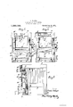
The above, and various other objects and advantages of this invention will in part be described in and in partunderstood from the following detailed description of the present preferred embodiment, the same being illustrated in the accompanying drawings, wherein Figure 1 is a front elevation of a vegetable and fruit dispenser constructed according to I the present invention, the device being closed and a container shown as resting on the platform;
Fig. 2 is a similar view disclosing the dis penser open and illustrating the parts of the a device when the latform is depressed or weighted down with the required quantity of the goods; a
Fig, 3 is a side elevation of the device in the position of Fig. 1, parts of the same being shown in section;
Fig. 4 is a vertical longitudinal section taken substantiall centrally through the device in the position of Fig. 1; 1
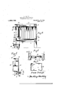
Fig. 5 is a horizontal section taken substantially on the line 5-5 of Fig. 3 and looking downwardly in the direction indicated by the arrows; i
Fig. 6 is a vertical section the structure illustrated in Fig. 5 on the line 6-6 thereof, and in the direction indicated by the arrows; and
Fig. 7 is a detail plan. view of the underside of the scale platform.
Referring to the drawings, wherein like parts are designated'by similar numerals of reference throughout the several views, the body part or frame of the device comprises. a pair of forward uprights or standards 10 and -11, connected together at their upper ends by a front cross piece 12 and reinforced taken through The space between the cross pieces 12 and i 13, and the standards 10 and 11 is preferabl closed inby a transparent panel 14, althoug any other suitable closure may be em loyed. The front portion of the frame thus ormed, constitutes a support for a pair of sides. Each side is (onstructed of a top rail 15 and a bottom rail 16, the rails supporting a plurality of slats 17 or the like, which extend between the rails and form the body of the side, and permit ins ection of the contents of the body through t e side.
The top rail 15 is joined to the front section at its upper end while the bottom rail 16 is joined to front section at a point below the cross piece 13. The rear end of the platform comprises a pair of standards, which are secured to the rear ends of the top and bottom rails 15 and 16, and which are interbraced by a top brace 19 and a lower or intermediate brace 20. The brace 19 is connected to the tops of the standards 18, while the brace 20 preferably lies in the horizontal plane of the side rails 16, and below the forward cross brace 13. The rear wall or portion of the structure may also be closed in b slats or bars 21, forming a grating for holc ing the contents in the body and at the same time permitting the inspection of the contents from outside the body.
The parts, thus described, may of course be made of any suitable material, but at present, they are constructed of wood as the latter is found to be the most practical and economical. A sheet metal bottom 22 is provided. The rear end of the bottom 22 is secured by a clamping strip 23 upon the upper face or edge of the rear cross brace 20. The lateral marginal edges of the bottom 22 are secured by lateral extensions of the clamping strip 23 to the upper edges or faces of the side rails 16, so as to completely inclose I the lower end of the body.
The intermediate portion of the sheet metal body 22 is depressed or arched downwardly, and slopes uniformly from the rear cross brace 20 to the forward edge of the bottom 22, which bottom projects forwardly beneath the front cross brace 13 to provide a trough or feeding mouth of a predetermined size downwardly through which the fruit and vegetables may roll when released. The forward lower corner of the cross piece 13 is preferably beveled or cut away to provide an inwardly and downwardly sloping face 24, which leads to the troughed bottom 22, to permit viewing of the contents of the trough and also easy access of the hand for picking out one or more of the articles to be dispensed, should it be found necessary to add an additional article for completing the weight. This inclined face 2 L also provides a hopper or opening through which articles may be returned to the spout or bottom 22,
should there be overflow incidentto the failure of shutting off the flow of the articles from the spout.
A gate 25 is mounted on the body frame at the forward end of the bottom or spout and is adapted to control the iiow of the articles or material from the spout. Th is gate 25 comprises a flat strip or board pivbted at 26 against the forward side offthe upright 10 at one side of the bottom 22 and the strip 25 is adapted to extend in av generalhorizo ntal direction across the front of the body, and is adapted to swing upon its pivot 26 within the limits of a strap or guard 27 which issecured to the opposite front standard or upright 11. The guard 27 is preferably of-substantially loop shape with its ends screwed or otherwise secured against the outer face of the upright 11, and the gate or strip 25 is of sufficient length to project from the strap 27 and beyond the outer edge of the upright 11 to form a handle 28 by means of which the gate 25 may swing down into the low fgr end of the strap 27, for closing the gate.
From Fig. 4t it will be noted that the top of the gate 25 terminates in spaced relation from and also below the plane of the upper portion of the cross brace 13, so that ample space is provided between the top of the gate 25 and the inclined face 2st to receive the hand for withdrawing or replacing articles.
as is found necessary.
To permit the quick and easy opening of the gate 25, particularly when both hands are occupied in the carrying of bundles or holding a receptacle in proper position for receiving the articles, a pedal or foot lever 29 is provided and is located upon the standard 11 at the side thereof so that the person dispensing the goods may stand at the front of the device and place the right foot on the pedal 29, depress it and thus open the gate 25.
This pedal 29 is provided with a substantially T-shaped head or shoe 30 upon its inner end, and the shoe or head is confined in a vertical guide 31 which is preferably in the form of a sheet metal strip overturned at its longitudinal edges, and with such edges closely spaced apart to form an undercut T-slot in which the shoe fits with the shank thereof projecting outwardly for supporting the pedal 29.
The pedal is connected by a flexible cord 32 with the outer or swinging end of the gate 25. The guide rail 31 is preferably secured against the outer face of a strip 33 secured upon the inner side of the front post 11, in position to permit the pedal 29 to project laterally beyond the post 11 a distance sufficient to receive the foot of the operator. The flexible cord 32 extends upwardly from the pedal 29 and through an opening 34 which is formed through the adjacent side rail 16 and thence upwardly and over a pair of pulleys 85 carried in a suitable block 36 seated in the upper part of the standard 11. The flexible cord 32 is trained over these pulleys 35jfind carried downwardly at the forward'side of the standard 11 and connected at its end by a strap 37 to the gate 25 at the inner side of the strap or guard 27.
Thusfdepression of the pedal 29 swings the gate 25 into open position. For the purpose of holding the gate in open position wherg'desired, the standard 11 is provided at ritsrouter side with a spring-retainer 38,
tainer 38 are closely spaced apa to yieldingly receive therehetweon the 11:. Mile 28 of the gatfas the a-er is swung into its raised position The r .ainer 38 is of sullicient strength to support the gate in raised position and the same time permits the r easing oi; the gate when slight p1 brought to bear upon the handle 28 in a diroction to close the gate.
Housed within the forward part of the body or frame of the device a supporting plat-form 39. This platform extends be tween the lower end portions of the stand-- ards and 11 and beneath the forward end. of the bottom or spout 22 so that a basket, such as shown in dotted lines at 40 in Fig. 1, may be placed upon the platform and when there positioned, is in proper p the articles or material as Jo same flow from the spout or bottom Theplatform 39 is sug'ipor d a n the lever mechanism 41 of a scale which is housed in a base ea so cured by straps as or the like to the inner sidesof the uprights .10 and 11 for not only reinforcing the uprights, but also for hour .ing and protecting the scalemechanism.
The lever 41 is connected by a link 44- to a scale beam 45? of approved construction, which is pivoted. at so to the front side of the top cross brace 12 and in position over the platform 39. The scale beam carries the usual adjustable weight 4? and -other purtenances for determining the diii'erent weights it is desired to place upon the platform 39, for supporting a yoke bracket 48 which embraces the outer end of the scale beam 4&5 for igniting the rise and fall oithe same.
It will he noted that the rams or body part of the dispenser is of such C"El1:l0l2i0ll that it houses and. supports the various parts oi? the dispensingand weighing apparatus,
so that such parts not only afford a support and a protection, but are so positioned that they may be used for interbracing and reinforcing the frame of the device.
Another feature of the device as thus constructed, is that while the contents mayiin. bulk be (sickly and easily delivered the basket or other container used 'it admits of the return or of the individual picking out of one or more of the articles according to whether an excess amount has been. delivered or whether the amount falls itly short of the weight desired.
In use, the person dispensing the goods places cont iner sill on the platform 39. The weight a? is then adjusted on the scale beam to the indication opposite the desired weight. This having been done, the person then places the :5 cos the latter action draws into its lhe retainer Y The cross brace 12 is also utilized c holds it in such open position so that the operator may release the footn As soon as the quantity-of goods has flowed from the spout 2 2 into the container 40 to an amount sulficient to swing the scale beam 45, the operator then quickly presses down upon the handle 28 ot the to close the latter.
Should the not be closed at the proper time and too much material or too man articles were delivered to the container 40, the,
person may easily pick out a few of the ar ticles from the container to lighten the weight therein and toss such articles back into the spout or bottom 22 through the passage 24.
On the other hand it the quantity in the container so does not come up to the desired weight, the oper l -*assage'2s and lift out one or more else, as is foundnecessary to make has adapted for practical usage and may or may easily insert the,
h deficiency in the weight. The devicealso he used for determining the exact.
weights well as handling the bulks ina quick and satisfactory manner.
It is of course understood that various changes and modifications may he made in the details of construction and design-of the above specifically described embodiment without dep the spirit of the inventiimti such changes and modifications be ing restricted only by the scope of the following claims.
lVhat is claimec is: 1. In a dispensing cc, hollow body adapted to receive articles to hedispensed and provided with a forwardly inclined bottom forming cho i a closing the outer end oithe chute pedal mounted upon the side of the body and connected to the gate for swine the same into openpositionupon de ression of the pedal, and a scale platform'inounted within the forward end of the bodyportion beneath said gate for supporting a container in position to receive articles from the spout.-
2. Inan article dispenser, a hollow portion. having an outlet spout at its for ward end sate closm the forward end of t z, v t: 1 the scout a nodal mounted moon the side .i 3 l .L
of the body portion and connected to said gate and adapted. to swing the latter into open position when the pedal'is depressed, means for yieldingly holding the. gate in open position, said gate being adapted to be manually released upon delivery of the required amount of material from the spout, and a scale platform housed within and sup ported by the forward end of said body por tion for supporting a container beneaththe spout.
inch
. In article dispenser, a hollow-body! 1 we material-1n built; n d bottom;
forward end of the body portion at one side thereof and extending across the forward end of said spout for closing the same, a
pedal mounted upon said body portion at 5 the other side thereof, a connection between said pedal and said ate for swingin the latter into open position when the pe a1 is depressed, and a scale platform mounted within the lower end of said body portion beneath the gate for supporting a container in proper position to receive articles from the 5 out.
4. n an article dispenser, a body portion comprising front and rear pairs of uprights, top and intermediate braces arranged between said pairs of uprights for interbracing the same, top'and bottom side rails joining said uprights to provide a hollow body adapted to receive articles to be dispensed, an inclined bottom carried between the 'uprights and said rails and inclined forwardly and downwardly to form a spout adapted to deliver material beneath an intermediate .brace at the front of the body, a gate pivoted at one end to one of the forward uprights and the gate extending across the forward end of said bottom to close the spout, a vertically slidable pedal mounted upon the opposite forward upright and having connection with the free end of said gate for swinging the latter upwardly when the pedal is depressed, and a wei hing scale mounted between and supporte from said forward uprights, whereby said scale is protected betweenthe uprights and whereby the platform of the scale may be supported in position to receive a container for articles delivered from the spout.
5. In an article dispenser, a hollow body 40 portion adapted to receive articles in bulk and having a forwardly inclined delivery spout at its forward end, a cross brace in the forward end of said body portion spaced above the bottom of the spout and having, a forwardly and downwardly inolinedfront face providing a passage leading down into the spout, a gate mounted upon the forward end of the body portion and extending across the forward end of the spout in spaced relation to said cross brace to permit insertion and removal of articles through said space into and from the spout, means for swinging the gate into open and closed positions, and a scale platform mounted in the forward end of said body portion beneath said gate. 6. In a dispensing device for articles, a hollow body portion adapted to receive articles in bulk, and provided with a forwardly and downwardly inclined delivery spout, the front wall of said body portion having a lower cross brace spaced above said spout to permit a passage beneath the cross brace through which the articles are adapted to flow in a restricted stream, a gate pivotizlly mounted upon the forward end of the body portion and adapted to extend across the forward end of said spout to check the flow of articles therefrom, said ate being spaced forwardly from said cross race whereby to provide between the gate and the cross brace a passage by means of which access may be readily gained to the spout when the gate is closed for removing articles from the spout and for replacing'the articles therein, and a support carried in the forward end of the "i5 body portion beneath the open end of the spout for maintaining a container in proper position for receiving the bulk of material h n the gate is vOIpBR I-U T PHILIPPS
Priority Applications (1)
| Application Number | Priority Date | Filing Date | Title |
|---|---|---|---|
| US455809A US1388198A (en) | 1921-03-26 | 1921-03-26 | Vegetable and fruit dispenser |
Applications Claiming Priority (1)
| Application Number | Priority Date | Filing Date | Title |
|---|---|---|---|
| US455809A US1388198A (en) | 1921-03-26 | 1921-03-26 | Vegetable and fruit dispenser |
Publications (1)
| Publication Number | Publication Date |
|---|---|
| US1388198A true US1388198A (en) | 1921-08-23 |
Family
ID=23810361
Family Applications (1)
| Application Number | Title | Priority Date | Filing Date |
|---|---|---|---|
| US455809A Expired - Lifetime US1388198A (en) | 1921-03-26 | 1921-03-26 | Vegetable and fruit dispenser |
Country Status (1)
| Country | Link |
|---|---|
| US (1) | US1388198A (en) |
Cited By (1)
| Publication number | Priority date | Publication date | Assignee | Title |
|---|---|---|---|---|
| US20170303703A1 (en) * | 2016-04-22 | 2017-10-26 | Salvatore C. Eso, JR. | Nut dispenser device |
-
1921
- 1921-03-26 US US455809A patent/US1388198A/en not_active Expired - Lifetime
Cited By (2)
| Publication number | Priority date | Publication date | Assignee | Title |
|---|---|---|---|---|
| US20170303703A1 (en) * | 2016-04-22 | 2017-10-26 | Salvatore C. Eso, JR. | Nut dispenser device |
| US10219635B2 (en) * | 2016-04-22 | 2019-03-05 | Salvatore C. Eso, JR. | Nut dispenser device |
Similar Documents
| Publication | Publication Date | Title |
|---|---|---|
| US2831591A (en) | Bulk package opener | |
| US4137689A (en) | Bag filling and weighing machine | |
| US2928551A (en) | Display rack for containers | |
| JP6961565B2 (en) | Combination weighing device | |
| US1388198A (en) | Vegetable and fruit dispenser | |
| US430355A (en) | Bag filler and holder | |
| US2586557A (en) | Sacking and weighing machine | |
| US2940642A (en) | Dispensing bin for vegetables, etc. | |
| US2623671A (en) | Bag filling machine with movably mounted funnel closing member | |
| US529528A (en) | Grocer s cabinet | |
| US1993451A (en) | Display and stock rack | |
| US2830687A (en) | Package bagging device | |
| US5775066A (en) | Device for the distribution of bulk articles and use of such a device | |
| US1839617A (en) | Store construction | |
| US2664224A (en) | Capsule computer and delivery device | |
| US3125236A (en) | X a attachment for a fork lift | |
| US1246334A (en) | Box-filler. | |
| US1830644A (en) | Apparatus for filling containers | |
| US2966770A (en) | Packaging device | |
| US1139257A (en) | Store-fixture. | |
| US1898416A (en) | Bin | |
| US2108302A (en) | Package delivering apparatus | |
| US1755045A (en) | Straw-serving machine | |
| US1372480A (en) | Bag-filling machine | |
| US2289705A (en) | Dispensing and weighing machine |