US138564A - Improvement in reverberatoryfurnaces - Google Patents
Improvement in reverberatoryfurnaces Download PDFInfo
- Publication number
- US138564A US138564A US138564DA US138564A US 138564 A US138564 A US 138564A US 138564D A US138564D A US 138564DA US 138564 A US138564 A US 138564A
- Authority
- US
- United States
- Prior art keywords
- plate
- furnace
- bearer
- plates
- recess
- Prior art date
- Legal status (The legal status is an assumption and is not a legal conclusion. Google has not performed a legal analysis and makes no representation as to the accuracy of the status listed.)
- Expired - Lifetime
Links
- XEEYBQQBJWHFJM-UHFFFAOYSA-N Iron Chemical compound [Fe] XEEYBQQBJWHFJM-UHFFFAOYSA-N 0.000 description 4
- 238000010276 construction Methods 0.000 description 3
- 210000002683 foot Anatomy 0.000 description 2
- 239000007789 gas Substances 0.000 description 2
- 229910052742 iron Inorganic materials 0.000 description 2
- 239000002184 metal Substances 0.000 description 2
- 229910052751 metal Inorganic materials 0.000 description 2
- 239000004927 clay Substances 0.000 description 1
- 230000000284 resting effect Effects 0.000 description 1
- 210000003371 toe Anatomy 0.000 description 1
Images
Classifications
-
- F—MECHANICAL ENGINEERING; LIGHTING; HEATING; WEAPONS; BLASTING
- F27—FURNACES; KILNS; OVENS; RETORTS
- F27B—FURNACES, KILNS, OVENS OR RETORTS IN GENERAL; OPEN SINTERING OR LIKE APPARATUS
- F27B9/00—Furnaces through which the charge is moved mechanically, e.g. of tunnel type; Similar furnaces in which the charge moves by gravity
- F27B9/14—Furnaces through which the charge is moved mechanically, e.g. of tunnel type; Similar furnaces in which the charge moves by gravity characterised by the path of the charge during treatment; characterised by the means by which the charge is moved during treatment
- F27B9/16—Furnaces through which the charge is moved mechanically, e.g. of tunnel type; Similar furnaces in which the charge moves by gravity characterised by the path of the charge during treatment; characterised by the means by which the charge is moved during treatment the charge moving in a circular or arcuate path
-
- C—CHEMISTRY; METALLURGY
- C21—METALLURGY OF IRON
- C21B—MANUFACTURE OF IRON OR STEEL
- C21B9/00—Stoves for heating the blast in blast furnaces
- C21B9/10—Other details, e.g. blast mains
Definitions
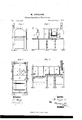
- Figure 1 is a front-end view of my improved furnace.
- Fig. 2 is a front-sideview of the same.
- Fig. 3 is a top view of'the same.
- Fig. 4 is a vertical longitudinal section of the same.
- My invention has for its object to furnish an improved set of furnace plates, to be used in the construction of puddling-furnaces, which shallbe simple in construction and convenient in use, enabling the furnace to be built and repaired at much less expense than when the furnace is constructed in the ordinary manner.
- the invention consists in the combination of the breast-plate with the side plate, as hereinafter described; inthe recess formed in the side plate at the side of the opening for the breast-plate to enable the bottom plate to be withdrawn through said opening; in the arrangement ofthe bearers with respect to each other and the bottom plates; in the recess formed in the end plate for the end-wall plate to be drawn through; in the combination of the pipe with paddling-furnace; and in the holes in the end bottom pla-tes in connection with the pipe, as hereinafter fully described; in the employment of iiag stones and metal columns for supporting a puddling-furnace; in the combination of the side plates with the metal columns for forming a puddling-furnace.
- a A are Hagv stones, upon which rest the lower ends of the columns B,to which the plates C D E are bolted.
- the size of the columns B should be about nine by one and onefourth inch; and their head and foot should be about nine by ten inches.
- the bearer J is about four inches wide and four and a half inches deep, and has its top beveled off so as to leave it about two inches wide, and has three lugs or toes cast upon it to keep the bottom plates from spreading.- In the top of the bearer J is cut a notch of i suitable size to receive the end of the-bearer L.
- the bearer K is made eXactlylike the bearer J, except thatfinstead of a notch, it has a section of about four inches cut from its middle part to receive the bearer L between the adjacent ends of its parts.
- the end of the bearer L is supported, at the proper level, by a chock or wed ge, l, driven between it and the head of the column B.
- the bearerL is made with two or more cross-bars.
- M N O are the bottom plates, the middle one, N, of which is made in two parts.
- the breast-plate P When it becomes necessary to change the middle plate N, the breast-plate P is removed, and the chock or wedge ldrawn out. This allows the end of the bearer L to drop upon the head of the column B.
- the half of the bottom plate N drops with the bearer L, and may be drawn out, through the breastplate opening and the recess e in the plate E, by means of a pair of blacksmiths7 tongs.
- the new plate may then be put in through the said opening and recess, and the plate and bearerraised into place by a crowbar, a little fire-clay being put upon the lip to joint them firmly together.
- the plate N can be changed without delaying the furnace more than fteenminutes.
- the breast-plate P can be changed alone without delaying the furnace at all. This is done by removing the loose pins 1o that keep the bottom of said plate in place by inserting the point of a crowbar in the recess el and prying the lower part of said plate P outward. This draws the upper part of theplate P down from the flan ges e2 which hold it when in place, and which project about, one and a quarter inch along the front of the upper part of the said plate I.
- Q is the end-wall plate, which is nine inches wide and four feet long, and beneath the ends of which are placed pieces of three-fonrths-inch iron.
- the end plate Gr is formed, threefourths of an inch below the plate Q, a recess, g1.
- the plate Q may be relnoved by knocking,1 out the iron pieces beneath the ends of the plate Q, which allows the said plate to drop three-fourths of an inch, when it maybe drawn out through the recess g1.
- the wall at the back of the fire-grate is made twelve inches thick, and is incased by the piece or flange g2 formed upon or attached to the end plate G, and which may be upon one or the other part of said plate, according as the furnace is to be right or left furnace.
- R is a pipe for drawing the air through the chills; and, also, to carry o the gases that accumulate under the furnace, and carry them above the heads of the workmen.
- m o are holes formed in the bottom plates to serve as inlets to the air and gases, which pass thence through the chills, and escape through the pipe R.
Landscapes
- Engineering & Computer Science (AREA)
- Chemical & Material Sciences (AREA)
- Mechanical Engineering (AREA)
- General Engineering & Computer Science (AREA)
- Manufacturing & Machinery (AREA)
- Materials Engineering (AREA)
- Metallurgy (AREA)
- Organic Chemistry (AREA)
- Furnace Charging Or Discharging (AREA)
Description
W. HUYLAN D.
Reverberatory Furnaces.
Patented Maw/6,1873'.
` Inventur.:
Per-
Ausma',
UNITED STATES PATENT OEETCE,
WILLIAM HOYLAND, OF NEWCASTLE, PENNSYLVANIA.`
IMPROVEMENT IN REVERBERATORV FURNACES.
Specification forming part of Letters Patent No. 138,564, dated May 6, 1873; application filed April 5, 1873.
To all whom t may concern:
Beit known that I, WILLIAM HOYLAND, of Newcastle, in the county of Lawrence and State of Pennsylvania, have invented a new and useful Improvement in Puddling Furnaces, of which the following is a specification:
Figure 1 is a front-end view of my improved furnace. Fig. 2 is a front-sideview of the same. Fig. 3 is a top view of'the same. Fig. 4 is a vertical longitudinal section of the same.
Similar letters of reference indicate corresponding parts.
` My invention has for its object to furnish an improved set of furnace plates, to be used in the construction of puddling-furnaces, which shallbe simple in construction and convenient in use, enabling the furnace to be built and repaired at much less expense than when the furnace is constructed in the ordinary manner. The invention consists in the combination of the breast-plate with the side plate, as hereinafter described; inthe recess formed in the side plate at the side of the opening for the breast-plate to enable the bottom plate to be withdrawn through said opening; in the arrangement ofthe bearers with respect to each other and the bottom plates; in the recess formed in the end plate for the end-wall plate to be drawn through; in the combination of the pipe with paddling-furnace; and in the holes in the end bottom pla-tes in connection with the pipe, as hereinafter fully described; in the employment of iiag stones and metal columns for supporting a puddling-furnace; in the combination of the side plates with the metal columns for forming a puddling-furnace.
A A are Hagv stones, upon which rest the lower ends of the columns B,to which the plates C D E are bolted. The size of the columns B should be about nine by one and onefourth inch; and their head and foot should be about nine by ten inches.
When two furnaces are placed side by side there are no division-plates between them below the tops of the columns B; but the inner columns ot' the two furnaces are bolted back to back. The columns B and the brackets F attached to the end plates Gr H thus take the whole weight of the furnace.` This construction leaves a clear open space beneath the furnaces, which greatly assists in keeping the bottom of the furnace cool. I are plates, resting, one end upon the brackets F and their other end upon the heads of the columns B, and which are designed to carry the side walls of the regrate. J K L are the bearers, which sustain the weight of the whole interior of them furnace. The bearer J is about four inches wide and four and a half inches deep, and has its top beveled off so as to leave it about two inches wide, and has three lugs or toes cast upon it to keep the bottom plates from spreading.- In the top of the bearer J is cut a notch of i suitable size to receive the end of the-bearer L. The bearer K is made eXactlylike the bearer J, except thatfinstead of a notch, it has a section of about four inches cut from its middle part to receive the bearer L between the adjacent ends of its parts. The end of the bearer L is supported, at the proper level, by a chock or wed ge, l, driven between it and the head of the column B. The bearerLis made with two or more cross-bars. M N O are the bottom plates, the middle one, N, of which is made in two parts.
When it becomes necessary to change the middle plate N, the breast-plate P is removed, and the chock or wedge ldrawn out. This allows the end of the bearer L to drop upon the head of the column B. The half of the bottom plate N drops with the bearer L, and may be drawn out, through the breastplate opening and the recess e in the plate E, by means of a pair of blacksmiths7 tongs. The new plate may then be put in through the said opening and recess, and the plate and bearerraised into place by a crowbar, a little lire-clay being put upon the lip to joint them firmly together.
In this way the plate N can be changed without delaying the furnace more than fteenminutes.
The breast-plate P can be changed alone without delaying the furnace at all. This is done by removing the loose pins 1o that keep the bottom of said plate in place by inserting the point of a crowbar in the recess el and prying the lower part of said plate P outward. This draws the upper part of theplate P down from the flan ges e2 which hold it when in place, and which project about, one and a quarter inch along the front of the upper part of the said plate I.
Q is the end-wall plate, which is nine inches wide and four feet long, and beneath the ends of which are placed pieces of three-fonrths-inch iron. In the end plate Gr is formed, threefourths of an inch below the plate Q, a recess, g1.
The plate Q may be relnoved by knocking,1 out the iron pieces beneath the ends of the plate Q, which allows the said plate to drop three-fourths of an inch, when it maybe drawn out through the recess g1.
lhis enables the plate Q to be changed without stopping the furnace or cutting away the brick-work above the said plate.
The wall at the back of the fire-grate is made twelve inches thick, and is incased by the piece or flange g2 formed upon or attached to the end plate G, and which may be upon one or the other part of said plate, according as the furnace is to be right or left furnace.
R is a pipe for drawing the air through the chills; and, also, to carry o the gases that accumulate under the furnace, and carry them above the heads of the workmen. m o are holes formed in the bottom plates to serve as inlets to the air and gases, which pass thence through the chills, and escape through the pipe R.
Having thus described myinvention, I claim as new and desire to secure by Letters Patent-' l. The combination of the breast-plate P with the plate E, substantially as herein shown and described.
2. The recess e1, formed in the plate E at the side ofthe opening;` for the breastplate P, to enable the plate N to be withdrawn through said opening, substantially as herein shown and described.
3. The arrangement .of the bearers J K L with respect to each other and the platesM N O, substantially as herein shown and described.
4. The recess formed in the end plate G for the end-wall plate Q to be drawn through, substantially as herein shown and described.
5. The combination ot' the pipe R with the puddling furnace, substantially as herein shown. and described, and for the purpose set forth.
6.v The holes m o in the plates M 0, in connection with the pipe R, substantially as herein shown and described, and for the purpose Set forth.
WILLIAM HOYLAND.
Witnesses:
W. E. REIS, K. UAMPBELL.
Publications (1)
| Publication Number | Publication Date |
|---|---|
| US138564A true US138564A (en) | 1873-05-06 |
Family
ID=2207978
Family Applications (1)
| Application Number | Title | Priority Date | Filing Date |
|---|---|---|---|
| US138564D Expired - Lifetime US138564A (en) | Improvement in reverberatoryfurnaces |
Country Status (1)
| Country | Link |
|---|---|
| US (1) | US138564A (en) |
Cited By (1)
| Publication number | Priority date | Publication date | Assignee | Title |
|---|---|---|---|---|
| US20050186003A1 (en) * | 2004-02-20 | 2005-08-25 | International Business Machines Corporation | Method and system for performing large scale distributed printing using a relational database |
-
0
- US US138564D patent/US138564A/en not_active Expired - Lifetime
Cited By (1)
| Publication number | Priority date | Publication date | Assignee | Title |
|---|---|---|---|---|
| US20050186003A1 (en) * | 2004-02-20 | 2005-08-25 | International Business Machines Corporation | Method and system for performing large scale distributed printing using a relational database |
Similar Documents
| Publication | Publication Date | Title |
|---|---|---|
| US138564A (en) | Improvement in reverberatoryfurnaces | |
| US125439A (en) | Improvement in the construction of ovens for bakers | |
| US638541A (en) | Cupola-furnace. | |
| US248081A (en) | Puddling-furnace | |
| US1843384A (en) | Furnace wall | |
| US64617A (en) | Improvement in heating and puddling furnaces | |
| US70042A (en) | Improved melting-furnaces foe the manufacture of steel | |
| US218529A (en) | Improvement in brick-kilns | |
| US151513A (en) | Improvement in coke-ovens | |
| US275119A (en) | Half to chaeles funke | |
| US124467A (en) | Improvement in smelting-furnaces | |
| US501200A (en) | wailes | |
| US1124559A (en) | Furnace. | |
| US2154980A (en) | Removable water-cooled slag pot | |
| US1724490A (en) | Smelting furnace | |
| US1477895A (en) | Fire arch | |
| US59214A (en) | Improved puddling-furnace | |
| US797932A (en) | Pan or bottom for open-hearth furnaces. | |
| US142152A (en) | Improvement in rotary puddling, melting, and heating furnaces | |
| US416085A (en) | Crucible for lead-furnaces | |
| US787636A (en) | Furnace. | |
| US183126A (en) | Improvement in construction and protection of puddling-furnaces | |
| US52813A (en) | Improved puddling-furnace | |
| US919187A (en) | Furnace. | |
| US1309433A (en) | betbick |