US137792A - Improvement in machines for bending tube-sockets - Google Patents
Improvement in machines for bending tube-sockets Download PDFInfo
- Publication number
- US137792A US137792A US137792DA US137792A US 137792 A US137792 A US 137792A US 137792D A US137792D A US 137792DA US 137792 A US137792 A US 137792A
- Authority
- US
- United States
- Prior art keywords
- mandrel
- sockets
- machines
- die
- improvement
- Prior art date
- Legal status (The legal status is an assumption and is not a legal conclusion. Google has not performed a legal analysis and makes no representation as to the accuracy of the status listed.)
- Expired - Lifetime
Links
- 238000005452 bending Methods 0.000 title description 9
- 238000000034 method Methods 0.000 description 2
- 101100379080 Emericella variicolor andB gene Proteins 0.000 description 1
- 239000002184 metal Substances 0.000 description 1
- 238000003466 welding Methods 0.000 description 1
Images
Classifications
-
- B—PERFORMING OPERATIONS; TRANSPORTING
- B21—MECHANICAL METAL-WORKING WITHOUT ESSENTIALLY REMOVING MATERIAL; PUNCHING METAL
- B21J—FORGING; HAMMERING; PRESSING METAL; RIVETING; FORGE FURNACES
- B21J7/00—Hammers; Forging machines with hammers or die jaws acting by impact
- B21J7/02—Special design or construction
- B21J7/14—Forging machines working with several hammers
-
- B—PERFORMING OPERATIONS; TRANSPORTING
- B21—MECHANICAL METAL-WORKING WITHOUT ESSENTIALLY REMOVING MATERIAL; PUNCHING METAL
- B21D—WORKING OR PROCESSING OF SHEET METAL OR METAL TUBES, RODS OR PROFILES WITHOUT ESSENTIALLY REMOVING MATERIAL; PUNCHING METAL
- B21D7/00—Bending rods, profiles, or tubes
- B21D7/06—Bending rods, profiles, or tubes in press brakes or between rams and anvils or abutments; Pliers with forming dies
Definitions
- My invention relates to the combination of an articulated mandrel for bending the middle portion of the skelp with the lower die and two other dies, in combination with the said die and mandrel for bending the remaining parts, the mandrel being tilted in its upward movement for the discharge of the socket, as hereinafter fully described.
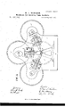
- Figure 1 is a plan view of the improved machine.
- Fig. 2, Sheet No. 2 is a side elevation of the same.
- Fig. 3 is an isometric-a1 view of the slide E and mandrel D.
- A is the bed-plate, andB and B the housings.
- O is a stationary die, into which the middle portion of the skelp m is bent by means of the mandrel D, connected at its inner end with the radial slide E, which moves in the bearing F on the front of the housing B.
- G and G are movable dies, arranged at angles with the die 0, for bending the outer portions of the skelp.
- These dies are provided with stems or slides E and E, which are caused to move in the bearings F and F I have represented on the front ends of the shafts G, G and G2 cams H, H and H for giving an inward motion to the mandrel D, and the dies 0 and O for bending the skelp, and springs I, 1 and I for returning them to their outer position.
- eccentrics the springs are dispensed with.
- the mandrel D receives its downward motion to press the middle portion of the skelp into the die 0 first; then the die 0 commences moving somewhat in advance of the die 0 so that one of the outer portions may be bent down on the mandrel and the other so as to overlap it for the welding process.
- the mandrel D is pivoted at its inner end to the slide E, as seen in Fig. 3, so that when the slide assumes its upward position the mandrel is thrown on a descending angle for the discharge of the bent skelp.
Landscapes
- Engineering & Computer Science (AREA)
- Mechanical Engineering (AREA)
- Bending Of Plates, Rods, And Pipes (AREA)
Description
2 Shts sheet 1. W. L. NEWSHAM.
Machines for Bending Tube Sockets. N0.137,792, PatentedApr iH5,l873.
AM PHOT0-UTH06IPAPH10 co. n1( osnomvs moms) 2 Shee1s-8heet 2.
PateniedApri!15,1873.
' ama AM. P110 m-UTHOGHAFHIC co. MY.( mean/ E1; PRacEss) UNITED f STATES PATENT ()FFICE MORRIS, TASKER & 00., OF SAME PLACE.
IMPROVEMENT IN'MAFCHINES Foe BENDING TUBE-SOCKETS.
gpecification forming part of Letters Patent No. 137,792, dated Apiil 15, 1873 application filed December 31, 1872.
To all whom it may concern.-
Be it known that I, WILLIAM L. NEwsHAM,
of the city of Philadelphia and State of Penn.
sylvania. have invented certain Improvements in Machines for Bending Metal Tube Sockets, of which the following is a specification:
My invention relates to the combination of an articulated mandrel for bending the middle portion of the skelp with the lower die and two other dies, in combination with the said die and mandrel for bending the remaining parts, the mandrel being tilted in its upward movement for the discharge of the socket, as hereinafter fully described.
Figure 1 is a plan view of the improved machine. Fig. 2, Sheet No. 2, is a side elevation of the same. Fig. 3 is an isometric-a1 view of the slide E and mandrel D.
Like letters in all the figures indicate the same parts.
Ais the bed-plate, andB and B the housings. O is a stationary die, into which the middle portion of the skelp m is bent by means of the mandrel D, connected at its inner end with the radial slide E, which moves in the bearing F on the front of the housing B. G and G are movable dies, arranged at angles with the die 0, for bending the outer portions of the skelp. These dies are provided with stems or slides E and E, which are caused to move in the bearings F and F I have represented on the front ends of the shafts G, G and G2 cams H, H and H for giving an inward motion to the mandrel D, and the dies 0 and O for bending the skelp, and springs I, 1 and I for returning them to their outer position.
I do not confine myself to this mode of operating the mandrel and dies, as eccentrics, or other suitable mechanism may be used. When eccentrics are used the springs are dispensed with.
On the shafts G, G and G there are gearwheels J, J and J which gear into the wheel J 3 on the driving-shaft G The slides E, E
and E are so arrangedin relation to each other and to the die 0, that the mandrel D receives its downward motion to press the middle portion of the skelp into the die 0 first; then the die 0 commences moving somewhat in advance of the die 0 so that one of the outer portions may be bent down on the mandrel and the other so as to overlap it for the welding process. The mandrel D is pivoted at its inner end to the slide E, as seen in Fig. 3, so that when the slide assumes its upward position the mandrel is thrown on a descending angle for the discharge of the bent skelp.
1 claim as my invention- 1. The combination of the articulated mandrel D, die 0, and slide E, operated by means of the cam H, or other suitable mechanism, in such a manner that by the downward movement of the slide the skelp is pressed by the mandrel into the die and bends the middle part of the skelp, and in the upward movement of the same, after the completion of the bending process by the other dies, the mandrel is tilted to discharge the socket from the mandrel, substantially as described.
2. The combination of two movable dies 0 and C for bending the outer portions of the skelp, in combination with the die (3 and mandrel D, either movable or stationary, the said dies moving one a little in advance of the other and in different planes with each other, and at angles with and above the horizontal plane of the lower die 0, substantially in the manner set forth.
WILLIAM L. NEWSHAM.
Witnesses:
J os. W. HARRISON, STEPHEN USTICK.
Publications (1)
| Publication Number | Publication Date |
|---|---|
| US137792A true US137792A (en) | 1873-04-15 |
Family
ID=2207207
Family Applications (1)
| Application Number | Title | Priority Date | Filing Date |
|---|---|---|---|
| US137792D Expired - Lifetime US137792A (en) | Improvement in machines for bending tube-sockets |
Country Status (1)
| Country | Link |
|---|---|
| US (1) | US137792A (en) |
Cited By (1)
| Publication number | Priority date | Publication date | Assignee | Title |
|---|---|---|---|---|
| US2436642A (en) * | 1943-01-04 | 1948-02-24 | Blackburn Aircraft Ltd | Reciprocating bender for making successive bends in metal tubes or rods |
-
0
- US US137792D patent/US137792A/en not_active Expired - Lifetime
Cited By (1)
| Publication number | Priority date | Publication date | Assignee | Title |
|---|---|---|---|---|
| US2436642A (en) * | 1943-01-04 | 1948-02-24 | Blackburn Aircraft Ltd | Reciprocating bender for making successive bends in metal tubes or rods |
Similar Documents
| Publication | Publication Date | Title |
|---|---|---|
| US137792A (en) | Improvement in machines for bending tube-sockets | |
| US134092A (en) | news ham | |
| US252440A (en) | Bolt-heading machine | |
| US534410A (en) | Sylvania | |
| US382537A (en) | Apparatus for forming sheet-metal can-bodies | |
| US195627A (en) | Improvement in machines for bending frog-plates for plows | |
| US503292A (en) | niedbinahaus | |
| US206031A (en) | Improvement in machines for forming tin-can bodies | |
| US262852A (en) | Machine for forming sheet-metal pans | |
| US143782A (en) | Improvement in horseshoe-machines | |
| US36878A (en) | Improvement in machines for making brace-jaws for steam-boilers | |
| US557922A (en) | Forcing-machine | |
| US1063918A (en) | Can-body-forming machine. | |
| US1206395A (en) | Can-body-making machine. | |
| US180810A (en) | Improvement in bending-machines | |
| US209747A (en) | Improvement in machines for making sheet-metal roofing | |
| US438364A (en) | Machine for forming gibs or flanges on metal bars | |
| US435481A (en) | Heel stiffener machine | |
| US698066A (en) | Side-seaming machine. | |
| US101513A (en) | Improved machine for making horseshoes | |
| US170300A (en) | Improvement in machines for bending metallic tubes | |
| US113167A (en) | Improvement in machines for forming pipe-elbows | |
| US160747A (en) | Improvement in pan-forming machines | |
| US268955A (en) | Machinery for forming the eyes of picks and other tools | |
| US72547A (en) | Improvement in machines for bending hooks |