US1340407A - Rotary crushing-mill - Google Patents
Rotary crushing-mill Download PDFInfo
- Publication number
- US1340407A US1340407A US248551A US24855118A US1340407A US 1340407 A US1340407 A US 1340407A US 248551 A US248551 A US 248551A US 24855118 A US24855118 A US 24855118A US 1340407 A US1340407 A US 1340407A
- Authority
- US
- United States
- Prior art keywords
- rollers
- cane
- crushing
- series
- mill
- Prior art date
- Legal status (The legal status is an assumption and is not a legal conclusion. Google has not performed a legal analysis and makes no representation as to the accuracy of the status listed.)
- Expired - Lifetime
Links
Images

Classifications
-
- C—CHEMISTRY; METALLURGY
- C13—SUGAR INDUSTRY
- C13B—PRODUCTION OF SUCROSE; APPARATUS SPECIALLY ADAPTED THEREFOR
- C13B10/00—Production of sugar juices
- C13B10/02—Expressing juice from sugar cane or similar material, e.g. sorghum saccharatum
- C13B10/06—Sugar-cane crushers
Landscapes
- Chemical & Material Sciences (AREA)
- Life Sciences & Earth Sciences (AREA)
- Biochemistry (AREA)
- Organic Chemistry (AREA)
- Crushing And Grinding (AREA)
- Crushing And Pulverization Processes (AREA)
Description
LQROSS.
ROTARY CRUSHING MILL. APPLICATION FILED AUG-6.1918.-
onwM
Vvm
APPLICATION FILED AUG.6,1918.
0 NM fi/ flz M w n r A m 6 W Wm M 7 9. Mr, m 7 21 z d3 2 m 4 k w w 2 a a, 4 7 Q6 Wm A m i \0 9 a \4 a I w I 4 V 0 J f m w W 7 .v w} l 1 if V 8% u I K I H1. 553mm f {3 .Lw m/w j 7 \vv 7w m 4 anuemtoz with "was LAFAYETTE BOSS, 015 EAST LYNN, WEST VIRGINIA.
ROTARY GRUSHING-MILL.
Specification of Letters Patent.
a en ed May 9 Application filed August 6, 1918. Serial No. 248,551.
To all whom it may 007108771.
lie it known that I, LAFAYETTE Rose, a citizen of the United States, residing at East llyun, in the county of :Vayne, State of est l irginia, have invented a new and useful Rotary Crushing-Mill; and I do hereby declare the following to be a full, clear, and exact description of the invention, such as will enable others skilled in the art to which it appertains to make and use the same.
This invention relates to an improved multiple roller crushing mill, and an object of the invention is to provide a device of this kind for crushing or grinding different kinds of cane, preferably sugar cane and the like, whereby it is possible to obtain all the cane juice.
A. further object of the invention is to provide a floating frame for carrying the upper series of rollers, so that the upper rollers may yield or move relative to the lower series.
A further object of the invention is to provide means for gearing the upper series of rollers with the lower series.
A. further object of the invention is to provide means for preventing the cane from lodging between the rollers of the upper series or those of the lower series.
The invention comprises further features and combination of parts as hereinafter set forth, shown in the drawings and claimed.
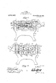
In the drawings Figure 1 is a View in side elevation of the improved machine constructed in accordance with the invention.
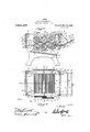
Fig. 2 is a view in side elevation of the opposite side of the machine.
Fig. 3 is a sectional view on line 3-3 of Fig. 2.
Fig. 4 is a sectional view on line 4:-4: of Fi 3.
iig. 5 is a sectional view on line 5-5 of Fig. 3.
Referring more especially to the drawings 1. designates a frame, which is preferably rectangular, and comprises the side pieces 2 having their upper portions cutaway as shown at 3, thereby forming the upright arms 4, to which the end pieces 5 and 6 are secured by bolts 7. A top piece 8 is secured by bolts 9 to the upright arms, thereby insuring rigidity for the frame as well as providing a cover for the operating or crushing mechanism. Mounted in bearings of the lower edges of the cutaway portions 3 of the side pieces are shafts 10, 11 and 12, there being a holding bearing strip '13 provided with semi-circular hearings or recesses 1i, which arch and hold the shafts 10, 11, and 12 in their bearings. The bearing strips 13 are secured in their proper positions by the screw bolts 16 and 17. The bolts or screws to are threaded through the bearing strips and into the side pieces, and are provided with nuts 18, for holding the plates 19 and 20 in position. The end pieces 5 and 6 are provided with entrance and discharge openings 21 and 22, through which the plates 19 and 20 extend, whereby the flanges 23 of said plates may extend downwardly on the outer faces of the end pieces. By means of the plates 19 and 20 the cane or other material to be crushed is guided toward and between the crushing rollers, and from said rollers. The bolts or screws 16 are 61011- gated, and have their upper ends fastened in any suitable manner at 24 in the top piece 8, and constitute guides 25. The inner portions of the upstanding arms 4 are provided with guide recesses 26, for the reception of the ends of the floating bars 27, the bottoms 28 of the recesses acting to support the floating bars 27 when in their lowermost positions. Arranged adjacent the bottom faces of the floating bars27 and also guided upon the extension bolts 16 are the clamping or holding bars 29. Suitable bolts 30 pass through the clamping or holding bars and arethreaded in the fioatingbars 27. Shafts 31, 32 and 33 are mounted in bearings .between the floating bars 27 and the clamping I hQlfl njgbars 29. Keyed to the shaftslO, 11 and 12 are corrugated crushing rollers 34, 35 and Keyed upon the shafts 31, 32 and 33 are crushing rollers .37, 38, and
39,]which are corrugated longitudinally as shown. These upper and lower series of rollers are spaced for the passage of the cane between them, and are graduated in diameters, so that the spaces between the rollers from the forward ends of the machine to the rear end consecutively diminish, whereby an easy passage of the cane between the rollers may be had. Arranged between the rollers 34, 35 and 36, and secured to the strips 13 by the bolts 17 are metallic guard strips 40, to prevent the cane or other material from finding its wa between the rollers 34 to 36 inclusive. gecured by the bolts 30 to the holding or clamping strips or bars 29, and between the rollers 37'to 39 inclusive are metallic guard strips 41, serving the same purpose, as served by the guard strips a0, that is to prevent cane from passing between the rollers 34s, 35 and 36. Mounted upon and rotatable with the shafts 10, 11 and 12 are gears 43, H and 4:5. Mounted upon and keyed to the shafts 31 to 33 inclusive are gears 46, i7 and 48. The upper series of gears 4:6 to 8 inclusive mesh with the lower series of gears 4:3 to 45 inclusive, so that the crushing rollers may rotate toward each other, for crushing the cane and carrying the same through the machine. One end of the shaft 31 is provided with a sprocket i9, and one end of the shaft 32 is provided with a pair of sprockets and 51, about the former of which a sprocket chain passes. This sprocket chain 52 also passes about and engages the sprocket 49. Passing about the sprocket 51 is a sprocket chain 53, which in turn passes about and engages the sprocket 54, which is mounted upon and keyed to the shaft 33. Keyed to and mounted upon the end of the shaft 33 adjacent the sprocket 5a is a pulley 55, which is engaged by the belt 56, to which power (not shown) may be connected, for operating the several geared together shafts and rollers, whereby the feeding and crushing of the cane may be accomplished. A chute 57 is arranged at the forward end of the machine and is provided with sides 58. The bottom of the chute is provided with a stepped. surface 59, and arranged adjacent one or two of the steps are rolls 60. This stepped surface and the rolls act to retard the passage of the cane toward and through the opening 21, so as to avoid feeding the machine excessively fast. Supporting rods 61 are connected at 62 to the sides of the chute. The upper ends of the rods 61 terminate in hooks 63 for engagement with the eyes 6%. A shoulder 65 is formed on the lower end of the chute to engage the plate 19, to prevent downward movement of the lower end of the chute. A receiving pan or tray (36 is fixed in any suitable manner between the sides of the frame below the rollers 3a to 36 inclusive. This pan or tray is designed for the reception of the cane juice from the cane.
The receiving pan or tray 66 is supported upon the flanges 6'7 of the opposite inner faces of the sides of the frame. The receiving pan or tray has an outlet opening 68 at its forward lower end, through which the cane juice may pass into a suitable receptacle (not shown). It is to be observed that the upper rollers 37 to 39 inclusive may yield or move slightly upwardly as the cane varies in thickness in passing between the rollers. These rollers are so movable owing to the bars 27 being vertically slidable upon the extension guides 16. It is to be noted that the teeth of the gears 43 to $5 inclusive and f6 to 48 inclusive are to be long enough in practice, so as to permit the rollers 37 to 39 to move upwardly, without the teeth of said gears disengaging. The cane is fed to the machine down the chute and in between the upper and lower series of rollers, whereby the cane juice is extracted from the cane so as to drop into the tray or pan, the pulp continuing on and passing out through the opening 22.
The invention having been set forth what is claimed as new and useful is In a mill for crushing cane, the combination with a frame of upper and lower series of crushing rollers, the upper series of rollers being carried in a vertically movable frame, gear connections between the upper and lower rollers, gear connections between the rollers of the upper series of rollers, means for driving one of the rollers of the upper series of roll rs whereby all of the rollers of both series will be rotated during a crushing operation, means between the rollers of each series for preventing the cane from passing through the vertically disposed spaces between the rollers, the vertically movable frame carrying the upper series of rollers allowing said upper series of rollers to be thrown out of gear connection with the lower series of rollers when an excessive amount of material is fed between the rollers.
In testimony whereof I have signed my name to this specification in the presence of two subscribing witnesses.
LAFAYETTE ROSS. llitnesses.
P. H. NAPIER, OLGA G. OSBURN.
Priority Applications (1)
| Application Number | Priority Date | Filing Date | Title |
|---|---|---|---|
| US248551A US1340407A (en) | 1918-08-06 | 1918-08-06 | Rotary crushing-mill |
Applications Claiming Priority (1)
| Application Number | Priority Date | Filing Date | Title |
|---|---|---|---|
| US248551A US1340407A (en) | 1918-08-06 | 1918-08-06 | Rotary crushing-mill |
Publications (1)
| Publication Number | Publication Date |
|---|---|
| US1340407A true US1340407A (en) | 1920-05-18 |
Family
ID=22939619
Family Applications (1)
| Application Number | Title | Priority Date | Filing Date |
|---|---|---|---|
| US248551A Expired - Lifetime US1340407A (en) | 1918-08-06 | 1918-08-06 | Rotary crushing-mill |
Country Status (1)
| Country | Link |
|---|---|
| US (1) | US1340407A (en) |
-
1918
- 1918-08-06 US US248551A patent/US1340407A/en not_active Expired - Lifetime
Similar Documents
| Publication | Publication Date | Title |
|---|---|---|
| US1340407A (en) | Rotary crushing-mill | |
| US252755A (en) | Roller-mill | |
| US358989A (en) | sanoe | |
| US32898A (en) | Machine fob | |
| US573500A (en) | woodman | |
| US554061A (en) | Corn-husking and fodder-cutting machine | |
| USRE2499E (en) | photx-lltho | |
| US639436A (en) | Cane-mill. | |
| US753696A (en) | Filtering apparatus. | |
| US820074A (en) | Sugar-cane mill. | |
| US957038A (en) | Ice-chipping machine. | |
| US1269424A (en) | Mill. | |
| US149214A (en) | Improvement in cider-mills | |
| US115112A (en) | Improvement in cider-mills | |
| US1010175A (en) | Confectionery machinery. | |
| US386407A (en) | kaylor | |
| US641931A (en) | Fruit-seeder. | |
| US410582A (en) | enoch | |
| US492964A (en) | Machine for cutting into strips and reeling or winding paper | |
| US1478924A (en) | Candy-forming machine | |
| US267555A (en) | Andreas meohwaet | |
| US348019A (en) | Cider-press | |
| US1055298A (en) | Machine for treating tankage. | |
| US456506A (en) | faulkner | |
| US594189A (en) | Mathias miller |