US13402A - Forming screw-threads - Google Patents
Forming screw-threads Download PDFInfo
- Publication number
- US13402A US13402A US13402DA US13402A US 13402 A US13402 A US 13402A US 13402D A US13402D A US 13402DA US 13402 A US13402 A US 13402A
- Authority
- US
- United States
- Prior art keywords
- plug
- threads
- insulator
- orifice
- bottles
- Prior art date
- Legal status (The legal status is an assumption and is not a legal conclusion. Google has not performed a legal analysis and makes no representation as to the accuracy of the status listed.)
- Expired - Lifetime
Links
- 239000012212 insulator Substances 0.000 description 40
- 210000003739 Neck Anatomy 0.000 description 22
- 239000000463 material Substances 0.000 description 22
- 239000007799 cork Substances 0.000 description 18
- 239000011521 glass Substances 0.000 description 16
- XEEYBQQBJWHFJM-UHFFFAOYSA-N iron Chemical compound [Fe] XEEYBQQBJWHFJM-UHFFFAOYSA-N 0.000 description 16
- 239000004575 stone Substances 0.000 description 14
- 210000001847 Jaw Anatomy 0.000 description 12
- 210000001699 lower leg Anatomy 0.000 description 12
- 241001513476 Amasa Species 0.000 description 10
- 229910052742 iron Inorganic materials 0.000 description 8
- 238000010276 construction Methods 0.000 description 6
- 239000000126 substance Substances 0.000 description 6
- 210000002414 Leg Anatomy 0.000 description 4
- 239000004927 clay Substances 0.000 description 4
- 229910052570 clay Inorganic materials 0.000 description 4
- 239000012530 fluid Substances 0.000 description 4
- 210000003414 Extremities Anatomy 0.000 description 2
- 239000000899 Gutta-Percha Substances 0.000 description 2
- 229920000588 Gutta-percha Polymers 0.000 description 2
- 240000000342 Palaquium gutta Species 0.000 description 2
- 229910000831 Steel Inorganic materials 0.000 description 2
- 230000001154 acute Effects 0.000 description 2
- 230000000875 corresponding Effects 0.000 description 2
- 230000002950 deficient Effects 0.000 description 2
- 229910052571 earthenware Inorganic materials 0.000 description 2
- 238000004519 manufacturing process Methods 0.000 description 2
- 239000002184 metal Substances 0.000 description 2
- 229910052751 metal Inorganic materials 0.000 description 2
- 239000006060 molten glass Substances 0.000 description 2
- 239000010959 steel Substances 0.000 description 2
Images
Classifications
-
- C—CHEMISTRY; METALLURGY
- C03—GLASS; MINERAL OR SLAG WOOL
- C03B—MANUFACTURE, SHAPING, OR SUPPLEMENTARY PROCESSES
- C03B9/00—Blowing glass; Production of hollow glass articles
- C03B9/13—Blowing glass; Production of hollow glass articles in gob feeder machines
- C03B9/14—Blowing glass; Production of hollow glass articles in gob feeder machines in "blow" machines or in "blow-and-blow" machines
- C03B9/16—Blowing glass; Production of hollow glass articles in gob feeder machines in "blow" machines or in "blow-and-blow" machines in machines with turn-over moulds
- C03B9/165—Details of such machines, e.g. guide funnels, turn-over mechanisms
Definitions
- AMASA STONE OF PHILADELPHIA, PENNSYLVANIA.
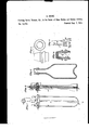
- Figure 1 1s a plan of the tool used for forming the necks and orifices of glass bottles, embracing my improvements.
- Fig. 2 is a section representing Fig. 1, cut through the line Z, Z.
- Fig. 3 represents the section of a bottle, showing the interior of the orifice formed by m lmprovements.
- Fig. 4 is the elevation o a telegraphic insulator.
- Fig. 5 is a section of Fig. 4, cut through the center, showing the interior formed with my improved plug represented in Fig. 6.
- my improvements consist in constructing the tools for forming the necks and orifices of bottles, so as to allow the plug which forms the interior of the orifice to turn with the bottle; while the material of the neck is worked around it.
- A is a metal spring, provide with a pair of steel jaws B, B, so as to make a pair of forming forceps, or tool, the interior of the jaws being made in such a shape as to give the neck and nozzle of the bottle, the desired form on the outside, as it is rotated between them, in a plastic state, and the jaws being pressed together upon the neck and nozzle of the bottle by the hand of the workman.
- the play C is arranged between the jaws B B so as to be readily inserted in the orifice of the bottle, when the jaws are applied outside of the neck and nozzle.
- the plug C is rovided with a shank D, fitted to the en of the spindle E, which is arranged to turn freely between the legs of the forceps in the osition represented; the rear end of the spindle bein supported by the screw F which is fitte to turn in a hole in the bow of the forceps; and the front end of the spindle is fitted to turn freely in the block G, which block is supported in its proper position, by the pivots H, H, fastened in opposite sides of the block G, and fitted to traverse freely in the holes provided for them, in the legs of the forceps or spring A.
- the plug C is perforated with the hole I, through its whole length and there is a hole J, throu h the side of the spindle, so as to ventilate t e interior of the bottle and allow its neck and orifice to be formed with facility around the plug; and also to facilitate its removal when the neck and orifice are completed.
- the shank D, of the plug C may be fitted tight enough to the spindle E, so as to hold it when it is driven in or it may be fastened in some other convenient manner; or the shank D may be arranged to turn in, or the plug C arranged to turn upon the spindle E which may be made stationary or otherwise as may be most convenient or desirable.
- the extremity of the plug C should be made smaller than its base which is next to the block G gradually tapering as it extends from its base, so that it can be withdrawn from the orifice of the bottle with facility; and made more tapering as it aproaches the apex so that it can be readily lnserted in the orifice of the bottle.
- the plug C is represented as having two angular scores a, a, made spirally upon it, so as to form a two threaded left handed male screw, the angle of the scores nearest or next to the apex, being made at a right angle to the center of the plugand the angle next to the base forming an acute angle with the center of the plug; the latter so as to give such a form to the orifice K, of the bottle Fig.
- the plug In ma ing bottles of glass or such substances as require to be wrought hot it is used with the forceps, (but in making stone, clay or earthen bottles, jugs, etc., where the material is wrought cold, the plug may be used without the forceps if preferred and the material worked around it with the fingers or such tools as may be convenientfor that purpose.) With the aid of my improved plug a female screw may be formed 1n the orifices of the bottles, jugs, etc., without materially increasing the expense of making them, so as to retain the corks and save the labor and expense of applying any other fastening, which renders them particularly desirable for efl'ervescent and other fluids which act strongly against the cork of the vessel which contains them, and further if the corkscrew used to draw the corks from such bottles, is made so short as not to perforate the cork entirely through its whole length, the corks may be used again and again, until they become defective from some other cause.
- the plug which forms the interior of the orifice L may be fitted to turn in that part of the mold which forms the base of the insulator and fitted so that it can be turned to unscrew the plug before the mold is opened so as to withdraw it partially or entirely from the insulator. Or that ortion of the plug M, (see Fig.
- a shank N (represented in dotted lines) ,fitted to turn in the block 0, and provided with a score P, for the point of the screw R, which is so arranged as to let the plug M, which has the male screw upon it,'turn freely; but prevents the shank from being drawn out of the block in drawing the plug out of the insulator, or other article formed upon it.
- the lug M is represented wit-h a two threa ed male screw upon it, the threads S, S, corresponding to the threads S, S in the insulator; one edge of the threads on the plug being at a right angle to the center of the plug, and the other sloped off so as to hold the material inserted in the insulator firmer and stronger.
- This plug is provided with a hole to ventilate the interior of the insulator as it is drawn out; which hole is represented by the dotted lines T, and the air to supply this hole may pass in between the plug M, and block 0, or a groove may be made in the end of the plug or block, or both around the shank N, and
- the block 0 may be fastened to the piston of a common press used in glassworks by the screws W, W, and a proper quantity of molten glass put into the mold which is to form the outside of the insulator, when the plug M may be forced down by the piston so as to form the interior of the insulator; when the piston is raised, the
- plug M turns and unscrews itself from the insulator which has been formed around it.
- articles which would be improved by having a female screw made in their interior may be made of glass, earthen or other materials which are formed in a molten, fluid, semifiuid or plastic state; may be made with a female screw in their interior with myimproved tools with the greatest facility.
- the interior or orifice may be partially filled with cork, gutta percha or such other substance as will answer the purpose, which should be screwed or forced in so as to fill, or partially fill the threads of the female screw in the insulator, so that it will not come out readily unless it is unscrewed for that purpose.
- the material in the orifice may be perforated and the tapering screw formed upon the end of the iron which is to be driven into the telegraph pole, may be screwed into it; or the iron may be driven in and the insulators screwed on afterward.
- the thread of the screw on the iron screwed in should be made in the same direction with the female screw in the insulator so as not to unscrew the cork or other material in the insulator by screwing in the iron which supports it.
- the telegraph wire may be fastened to the insulator by a wire passing around it in the score X provided for that purpose.
Description
A. STONE- Forming Screw Threads, &c., in the Necks of Glass Bottles and Similar Articles.
Patented Aug. 7, 1855.7
- [Pans MLWW. W n. c.
UNITED STATES PATENT OFFICE.
AMASA STONE, OF PHILADELPHIA, PENNSYLVANIA.
FORMING SCREW-THREADS, &c., IN THE NECKS OF GLASS BOTTLES AND SIMILAR ARTICLES.
Specification of Letters Patent No. 13,402, dated August 7, 1855.
To all whom it may concern:
Be it known that I, AMASA STONE, of Philadelphia, in the county of Philadelphia and State of Pennsylvanla, have invented certain new and useful improvements in tools for forming the orifices of glass, earthen, or other bottles, and the orifices or interior of insulators for telegraphs and for such other purposes as it can be applied to advantage; and I do hereby declare that the same are described and represented in the following specifications and drawin To enable others skilled in the art to ma e and use my improvements I will proceed to describe their construction and use,- referring to the drawings in which the same letters indicate like parts, in each of the figures.
Figure 1, 1s a plan of the tool used for forming the necks and orifices of glass bottles, embracing my improvements. Fig. 2, is a section representing Fig. 1, cut through the line Z, Z. Fig. 3, represents the section of a bottle, showing the interior of the orifice formed by m lmprovements. Fig. 4, is the elevation o a telegraphic insulator. Fig. 5, is a section of Fig. 4, cut through the center, showing the interior formed with my improved plug represented in Fig. 6.
The nature of my improvements consist in constructing the tools for forming the necks and orifices of bottles, so as to allow the plug which forms the interior of the orifice to turn with the bottle; while the material of the neck is worked around it.
In the above mentioned drawings A is a metal spring, provide with a pair of steel jaws B, B, so as to make a pair of forming forceps, or tool, the interior of the jaws being made in such a shape as to give the neck and nozzle of the bottle, the desired form on the outside, as it is rotated between them, in a plastic state, and the jaws being pressed together upon the neck and nozzle of the bottle by the hand of the workman.
In order to prevent the jaws of the forceps from closing the orifice of the bottle while they are forming the outside, the play C is arranged between the jaws B B so as to be readily inserted in the orifice of the bottle, when the jaws are applied outside of the neck and nozzle. The plug C, is rovided with a shank D, fitted to the en of the spindle E, which is arranged to turn freely between the legs of the forceps in the osition represented; the rear end of the spindle bein supported by the screw F which is fitte to turn in a hole in the bow of the forceps; and the front end of the spindle is fitted to turn freely in the block G, which block is supported in its proper position, by the pivots H, H, fastened in opposite sides of the block G, and fitted to traverse freely in the holes provided for them, in the legs of the forceps or spring A. The plug C, is perforated with the hole I, through its whole length and there is a hole J, throu h the side of the spindle, so as to ventilate t e interior of the bottle and allow its neck and orifice to be formed with facility around the plug; and also to facilitate its removal when the neck and orifice are completed. The shank D, of the plug C, may be fitted tight enough to the spindle E, so as to hold it when it is driven in or it may be fastened in some other convenient manner; or the shank D may be arranged to turn in, or the plug C arranged to turn upon the spindle E which may be made stationary or otherwise as may be most convenient or desirable.
The extremity of the plug C should be made smaller than its base which is next to the block G gradually tapering as it extends from its base, so that it can be withdrawn from the orifice of the bottle with facility; and made more tapering as it aproaches the apex so that it can be readily lnserted in the orifice of the bottle.
The plug C, is represented as having two angular scores a, a, made spirally upon it, so as to form a two threaded left handed male screw, the angle of the scores nearest or next to the apex, being made at a right angle to the center of the plugand the angle next to the base forming an acute angle with the center of the plug; the latter so as to give such a form to the orifice K, of the bottle Fig. 3, as will permit the cork to be readily forced in; and the former to hold the cork in when its elasticity expands it, or the pressure of the contents of the bottle acting in conjunction with the pressure which forces it in, expands it into the threads of the female screw formed by the male screw on the plug C, so as to efiectually hold the cork in the orifice K, against the pressure of the contents of the bottle; and at the same time allow the cork to be readily removed by a right handed corkscrew provided with a collar (as many of them are) to come against the top of the cork so as to turn it with the corkscrew to make it drawn out easier out of common bottles; but to unscrew the corks from the orifices of bottles formed as above described with a left handed female screw on the interior of the orifice I have described this lug C as being made in the form of a left handed two threaded male screw, but the screw upon it may be either right handed or left with a single, or such a number of threads as may be desirable for the purpose intended; or the plug may be made conical, spheroidal, elliptical or angular with three, four or more sldes, or in such form as may be desirable provided it is made largest at the base and tapering from the base to the end or a ex.
In ma ing bottles of glass or such substances as require to be wrought hot it is used with the forceps, (but in making stone, clay or earthen bottles, jugs, etc., where the material is wrought cold, the plug may be used without the forceps if preferred and the material worked around it with the fingers or such tools as may be convenientfor that purpose.) With the aid of my improved plug a female screw may be formed 1n the orifices of the bottles, jugs, etc., without materially increasing the expense of making them, so as to retain the corks and save the labor and expense of applying any other fastening, which renders them particularly desirable for efl'ervescent and other fluids which act strongly against the cork of the vessel which contains them, and further if the corkscrew used to draw the corks from such bottles, is made so short as not to perforate the cork entirely through its whole length, the corks may be used again and again, until they become defective from some other cause.
In making insulators for telegraphs such as are represented in Figs. 4, and 5, formed in a mold; the plug which forms the interior of the orifice L may be fitted to turn in that part of the mold which forms the base of the insulator and fitted so that it can be turned to unscrew the plug before the mold is opened so as to withdraw it partially or entirely from the insulator. Or that ortion of the plug M, (see Fig. 6,) may e provided wit-h a shank N, (represented in dotted lines) ,fitted to turn in the block 0, and provided with a score P, for the point of the screw R, which is so arranged as to let the plug M, which has the male screw upon it,'turn freely; but prevents the shank from being drawn out of the block in drawing the plug out of the insulator, or other article formed upon it. The lug M is represented wit-h a two threa ed male screw upon it, the threads S, S, corresponding to the threads S, S in the insulator; one edge of the threads on the plug being at a right angle to the center of the plug, and the other sloped off so as to hold the material inserted in the insulator firmer and stronger. This plug is provided with a hole to ventilate the interior of the insulator as it is drawn out; which hole is represented by the dotted lines T, and the air to supply this hole may pass in between the plug M, and block 0, or a groove may be made in the end of the plug or block, or both around the shank N, and
a hole or opening fromthe groove to the side of the block as represented in dotted lines at V, to supply the hole T with air. The block 0 may be fastened to the piston of a common press used in glassworks by the screws W, W, and a proper quantity of molten glass put into the mold which is to form the outside of the insulator, when the plug M may be forced down by the piston so as to form the interior of the insulator; when the piston is raised, the
plug M, turns and unscrews itself from the insulator which has been formed around it. I contemplate that articles which would be improved by having a female screw made in their interior, may be made of glass, earthen or other materials which are formed in a molten, fluid, semifiuid or plastic state; may be made with a female screw in their interior with myimproved tools with the greatest facility.
When insulators are made as above mentioned the interior or orifice may be partially filled with cork, gutta percha or such other substance as will answer the purpose, which should be screwed or forced in so as to fill, or partially fill the threads of the female screw in the insulator, so that it will not come out readily unless it is unscrewed for that purpose. After the insulators are properly filled the material in the orifice may be perforated and the tapering screw formed upon the end of the iron which is to be driven into the telegraph pole, may be screwed into it; or the iron may be driven in and the insulators screwed on afterward. The thread of the screw on the iron screwed in, should be made in the same direction with the female screw in the insulator so as not to unscrew the cork or other material in the insulator by screwing in the iron which supports it. The telegraph wire may be fastened to the insulator by a wire passing around it in the score X provided for that purpose.
I believe I have described the construction operation and use of my improvements in tools for forming orifices of bottles, jugs, telegraphic insulators, etc., so as to enable any person skilled in the art, to make and use the same. I will now specify what I desire to secure by Letters Patent.
What I claim as my invention in the construction of tools for forming screw threads, angular or other scores in the necks described.
- AMASA STONE. Witnesses:
YORK MATTHEWS, J. SNIDER,
To theflommc'ssz'oner of Patents:
The petition of SARAH T. STONE, administratrix to the estate of AMASA STONE, deceased, late of Philadelphia, Pennsylvania, respectfully represents: That your petitioner has made application for an extension of the patent granted to the said AMASA STONE August 7th, 1855, but that she is advised that the terms and claim of said patent are too broad as embracing the manufacture of earthen ware or ware of other material than glass. Your petitioner, therefore, as the legal representative of the heirs of the patentee, hereby enters her disclaimer to the application of said patent to any and all materials and manufactures other than glass; and in particular enters her disclaimer to the following words and sentences contained in the schedule or specification of said patent, to wit: On page 1 of said schedule, line 5, the words, earthen or other, and in the next line below, the words, and for such other purposes as itcan be applied to advantage. On page 2 of the sald schedule the following sentence, beginning at line 16: In making bottles of glass, or such substances as re uire to be wrought hot, it is used with the orceps, but in making stone, clay or earthen bottles, jugs, etc., when the material is wrought cold, the plug may be used without the forceps if preferred and the material worked around it with the fingers or such tools as may be convenient for that purpose. On page 3 of said schedule, line 6, the words earthen or other. And she hereby enters her disclaimer to the following words and phrases in the claim or to so much of the claim as is expressed in these words, to wit, the words earthen or other and the words jug or other article. And'further that your petitioner has paid ten dollars into the Treasury of the United States agreeably to the requirements of the act of Congress in that case made and provided.
SARAH T. STONE, Admz'nistmtm'w of A. Stone, deceased.
Witnesses:
WALTER D. swim, I. L. WILLOUGHBY.
Publications (1)
| Publication Number | Publication Date |
|---|---|
| US13402A true US13402A (en) | 1855-08-07 |
Family
ID=2073732
Family Applications (1)
| Application Number | Title | Priority Date | Filing Date |
|---|---|---|---|
| US13402D Expired - Lifetime US13402A (en) | Forming screw-threads |
Country Status (1)
| Country | Link |
|---|---|
| US (1) | US13402A (en) |
Cited By (4)
| Publication number | Priority date | Publication date | Assignee | Title |
|---|---|---|---|---|
| WO2010090602A1 (en) * | 2009-02-04 | 2010-08-12 | Data Security Systems Solutions Pte Ltd | Transforming static password systems to become 2-factor authentication |
| US20150232846A1 (en) * | 2013-08-16 | 2015-08-20 | Rana Therapeutics, Inc. | Pseudocircularization oligonucleotides for modulating rna |
| US9156719B2 (en) | 2010-05-31 | 2015-10-13 | Owens-Brockway Glass Container Inc. | Glass container with internally threaded neck |
| US10618831B2 (en) * | 2018-01-10 | 2020-04-14 | Owens-Brockway Glass Container Inc. | Parison plunger actuation |
-
0
- US US13402D patent/US13402A/en not_active Expired - Lifetime
Cited By (6)
| Publication number | Priority date | Publication date | Assignee | Title |
|---|---|---|---|---|
| WO2010090602A1 (en) * | 2009-02-04 | 2010-08-12 | Data Security Systems Solutions Pte Ltd | Transforming static password systems to become 2-factor authentication |
| US9156719B2 (en) | 2010-05-31 | 2015-10-13 | Owens-Brockway Glass Container Inc. | Glass container with internally threaded neck |
| US9440761B2 (en) | 2010-05-31 | 2016-09-13 | Owens-Brockway Glass Container Inc. | Process and equipment for the fabrication of glass containers with internally threaded neck |
| US20150232846A1 (en) * | 2013-08-16 | 2015-08-20 | Rana Therapeutics, Inc. | Pseudocircularization oligonucleotides for modulating rna |
| US10618831B2 (en) * | 2018-01-10 | 2020-04-14 | Owens-Brockway Glass Container Inc. | Parison plunger actuation |
| US11814310B2 (en) | 2018-01-10 | 2023-11-14 | Owens-Brockway Glass Container Inc. | Parison plunger actuation |
Similar Documents
| Publication | Publication Date | Title |
|---|---|---|
| US2135237A (en) | Closure for containers | |
| DE102004023796A1 (en) | can | |
| DE1432217A1 (en) | plastic bottle | |
| US13402A (en) | Forming screw-threads | |
| US30106A (en) | John focer | |
| DE60315467T2 (en) | bottle Cap | |
| US2160963A (en) | Collapsible container | |
| EP1480916B1 (en) | Bottle, method for the production thereof, method for filling a bottle, and method for opening a bottle | |
| DE102009050907A1 (en) | Plastic corks for beverage and liquid bottles | |
| EP3181470B1 (en) | Glass bottle for use with swing stopper | |
| DE3640512A1 (en) | STORAGE AND POURING JAR FOR A BEVERAGE CAN | |
| DE60307666T2 (en) | Method for forming a closure and securing device and their application to containers | |
| US620663A (en) | Bottle or jar stopper | |
| DE2006613B2 (en) | Universal tongs for bottle cap removal - using crown cork lifter over hinge point with recesses as wire cutters | |
| US1062458A (en) | Cork-extractor. | |
| DE202006010440U1 (en) | Combi-closure for containers has closure body, handle that can be removed from closure body with internal thread engaged by external thread of closure body | |
| CH456374A (en) | Bottle cap | |
| DE20102782U1 (en) | Centering cap for bottles | |
| DE227971C (en) | ||
| US14982A (en) | Improved method of drawing fluids from bottles | |
| DE852661C (en) | Bottle cap that prevents refilling | |
| DE29013C (en) | Asbestos stoppers to keep empty bottles clean and to preserve the contents after filling | |
| US22129A (en) | John l | |
| US594763A (en) | Edward c | |
| CH237086A (en) | Dropper bottle. |