US1336070A - Carbureter - Google Patents
Carbureter Download PDFInfo
- Publication number
- US1336070A US1336070A US148599A US14859917A US1336070A US 1336070 A US1336070 A US 1336070A US 148599 A US148599 A US 148599A US 14859917 A US14859917 A US 14859917A US 1336070 A US1336070 A US 1336070A
- Authority
- US
- United States
- Prior art keywords
- liquid
- air
- chamber
- fuel
- valve
- Prior art date
- Legal status (The legal status is an assumption and is not a legal conclusion. Google has not performed a legal analysis and makes no representation as to the accuracy of the status listed.)
- Expired - Lifetime
Links
- 239000007788 liquid Substances 0.000 description 29
- 239000000446 fuel Substances 0.000 description 22
- 238000010276 construction Methods 0.000 description 9
- 239000000203 mixture Substances 0.000 description 4
- 238000005192 partition Methods 0.000 description 4
- 230000001105 regulatory effect Effects 0.000 description 3
- 239000007921 spray Substances 0.000 description 3
- 239000002360 explosive Substances 0.000 description 2
- 238000004519 manufacturing process Methods 0.000 description 2
- 238000000034 method Methods 0.000 description 2
- 239000002245 particle Substances 0.000 description 2
- 239000004215 Carbon black (E152) Substances 0.000 description 1
- LFQSCWFLJHTTHZ-UHFFFAOYSA-N Ethanol Chemical compound CCO LFQSCWFLJHTTHZ-UHFFFAOYSA-N 0.000 description 1
- 238000002485 combustion reaction Methods 0.000 description 1
- 239000011928 denatured alcohol Substances 0.000 description 1
- 239000008246 gaseous mixture Substances 0.000 description 1
- 229930195733 hydrocarbon Natural products 0.000 description 1
- 150000002430 hydrocarbons Chemical class 0.000 description 1
- 230000008016 vaporization Effects 0.000 description 1
Images

Classifications
-
- F—MECHANICAL ENGINEERING; LIGHTING; HEATING; WEAPONS; BLASTING
- F02—COMBUSTION ENGINES; HOT-GAS OR COMBUSTION-PRODUCT ENGINE PLANTS
- F02M—SUPPLYING COMBUSTION ENGINES IN GENERAL WITH COMBUSTIBLE MIXTURES OR CONSTITUENTS THEREOF
- F02M17/00—Carburettors having pertinent characteristics not provided for in, or of interest apart from, the apparatus of preceding main groups F02M1/00 - F02M15/00
- F02M17/18—Other surface carburettors
- F02M17/20—Other surface carburettors with fuel bath
- F02M17/22—Other surface carburettors with fuel bath with air bubbling through bath
-
- Y—GENERAL TAGGING OF NEW TECHNOLOGICAL DEVELOPMENTS; GENERAL TAGGING OF CROSS-SECTIONAL TECHNOLOGIES SPANNING OVER SEVERAL SECTIONS OF THE IPC; TECHNICAL SUBJECTS COVERED BY FORMER USPC CROSS-REFERENCE ART COLLECTIONS [XRACs] AND DIGESTS
- Y10—TECHNICAL SUBJECTS COVERED BY FORMER USPC
- Y10S—TECHNICAL SUBJECTS COVERED BY FORMER USPC CROSS-REFERENCE ART COLLECTIONS [XRACs] AND DIGESTS
- Y10S261/00—Gas and liquid contact apparatus
- Y10S261/49—Suction operated feed valve
Definitions
- the present invention relates to means of carburation, and aims to devise an improved construction of such means with a view to producing 5 more effective and intimate mixing action between the liquid fuel used ap ended claim.
- Fig. 2 is a vertical section taken onthe line HH of Fig. 1;
- Fig. 3 is an endelevation of the device
- the lower section 3 is formed with partitions 6 and 8 for inclosing a' liquid fuel supply chamber, the space between said partitions being arranged as a float chamber (see Fig. 2) in communication with the remainder of the fuel supply chamber by way of the opening 10 in the base of the partition 8.
- the remainder of the space forming the interior of the casing may be designated as a vacuum chamber 12, the vacuum action within which is maintained by the engine suction through the connection 14 leading from the intake manifold of the engine (not shown) and communicating with the chamber 12 by way of the elbow conduit passage 16 which is provided with the ordinary butterfly valve control 18 and extends down into the section 3 of the casing between the partition 6 and the outer wall of the casing.
- the carbureter shown consists of a casing having a substantially circular liquid chamber in which operates the float 30, a second chamber for the perforate portion 41 of the valve which communicates with the liquid chamber through the port 10, and a suction port diametrically opposite the second chamber from which the tube 16 leads, and that an with the valve plug 20 having its outer end 'secured to a pipe connection 22.
- the inner end of the valve plug 20 provides a valve seat for a needle valve 24 and also supports a tubular guide member 26 having the ports 28 adjacent Said Valve seat.
- the valve 2 is automatically actuated to maintain a substantially constant level of the fuel in said fuel chamber by the action of a float 30 having a central passage for accommodating the guide member 26 and adapted to engage valve-actuating arms 32 which are pivotally mounted within the upper end portion of the member 26 where said arms are provided with suitable connections with the stem of said valve.
- Air for carburation purposes is admitted from the exterior of the casing by way of an elbow passage 34 formed by a conduit constructed integral with the upper section 2 of the casing, said conduit having the inlet fuel and a part or all of the air delivered to the liquid below the level of its surface.
- a conduit constructed integral with the upper section 2 of the casing said conduit having the inlet fuel and a part or all of the air delivered to the liquid below the level of its surface.
- One form of such adjustable member is illustrated in Figs. 2 and 4, and comprises a tubular slide 40 operating within the verti-.
- the adjustable slide member 40 may be regulated by means of a lever 44 pivoted within the horizontal portion of the conduit 34 and connected by a link 46 with the slide 40, said lever being operated by a rod 48 from the drivers seat.
- the arrangement is such that the slide may be elevated practically clear of the surface of the liquid or be lowered sufiiciently to submerge the extension 41 to any desired extent below thelevel of the liquid, the drawings illustrating said slide member in its raised position.
- FIGs. 5 and 6 Alternative forms of construction for regulating the degree of intermingling of air and liquid fuel are illustrated in Figs. 5 and 6.
- the form shown in Fig. 6 differs from that already described merely in constructing the adjustable slide member 40' as .a hollow cylinder of uniform diameter and raising and lowering the same to bring its lower end. to the proper elevation with reference to the surface of the liquid fuel, but omitting the feature of the air distributing openings.
- the conduit 34 is extended entirely to the bottom of the liq-- uid fuel supply chamber and thelower half of said'conduit provided with a helically arranged slot opening 50.
- the adjustable slide member 40" in this case is also lengthened to extend to the bottom of the fuel supply chamber and provided with a longitudinal series of perforations 52 for cooperating with the slot opening 50 in the delivery of the air to the fuel liquid.
- the adjustment of the slide member 40 is effected by rotating it through the medium of a rod" 54 extending up through the section 2 ofthe casing where any suitable connection (not shown) may be associated with the rod for operating the same.
- rotating the slide member 40" into different positions serves to present different openings 52 in register with the opening 50, and this register of the openings, and consequent delivery of the air, may be made to take place at any desired elevation.
- An auxiliary air valveconstruction is provided in communication with the vacuum chamber 12, the same comprising a valve cage 56 adapted to be threaded into an offset portion 58 of the section 2 of the casing, said valve cage carrying the check valve 60 secured to a valve stem 62 and operating under the influence of the engine suction 'against the action of two springs 64 and 66, the tension of which may be adjusted in an obvious manner by means of the nuts 68 retaining the spring 64 and the guide plug 70 threaded into said offset portion 58 into engagement with the spring 66 and held set by the lock nut 72.
- the degree of richness of the explosive mixture which is formed may be conveniently and accurately controlled by means of the adjustable slide member or extension, and where this memberis formed with the perforations for distributing the air flow, this produces somewhat of anozzleeifect, distributing the air how and dividing it into strongvigorous currents greatly accelerated in velocity, which simply surge through the fuel liquid and violently agitate the same.
- the arrangement of perforations as in Figs. 2 and 5 permits the slide member to be adjusted so that the air flow may be caused to take place entirely through the mass of liquid,
- a carbureter comprising a casing, a liquid chamber in the casing having a float- -ontrol valved-inlet opening therein, a second chamber communicating at its lower portion with the first chamber and having a space above it, a third chamber diametrically opposite the second chamber, a suction pipe depending within said third chamber and communicating with said space, an air inlet port in the casing above the liquid level in the second chamber, a sliding air-controlling member in the air-inlet port and movable toward and away from said liquid and an auxiliary air valve adapted to admit air to said space.
Landscapes
- Engineering & Computer Science (AREA)
- Chemical & Material Sciences (AREA)
- Combustion & Propulsion (AREA)
- Mechanical Engineering (AREA)
- General Engineering & Computer Science (AREA)
- Control Of The Air-Fuel Ratio Of Carburetors (AREA)
Description
D. L. F. COOMBS.
CARBURETER.
APPLICATION FILED FEB. 14, I917.
?atented Apr. 6, 1929.
2 SHEET$-SHEET 1.
w a W m w o was:
D. L. F. COOMBS.
CARBURETER.
APPLICATION FILED FEB. 14, I917.
UNITED, STATES PATENT orunon.
DANIEL L. F. COOMBS, OF KANSAS CITY, MISSOURI.
CARBURETER.
To all whom it may concern:
Be it known that I, DANIEL L. F. CooMBs, a citizen of the United States, residing at Kansas City, in the county of Jackson, State of Missouri, have invented certain new and useful Improvements in Carbureters, of which the following is a full and exact specification.
I The present invention relates to means of carburation, and aims to devise an improved construction of such means with a view to producing 5 more effective and intimate mixing action between the liquid fuel used ap ended claim.
and the air which is supplied'thereto, with theultimate object of deriving a satisfactory grade of dry gaseous fuel from practically any of the available grades of liquid fuel.
To this end an arrangement has been provided whereby the engine suction is so utilized as to deliver air to the liquid fuel supply in such a manner as to produce a flow of air into or through said liquid and eii'ect a turbulent churning action on the latter and a consequent complete and thorough intermingling of the air and liquid. I
It is also sought to} devise a construction of the generalcharacter indicated in which proper provision is made for varying the action of the air on the liquid fuel and the consequent intermingling efiect, for the purpose of regulating the character of the explosive mixture.
It is a further object to produce an extremely simple and efficient arrangement and construction for accomplishing the desired purpose, havingno complicatedmecha-nism to get out of: order, and which will be. economical and inexpensive to manufacture.
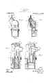
With these general objects in view, the invention will now be described with reference to the accompanying drawings illustrating means for embodying the improvements in actual practice, after which those features and combinations deemed to be novel will be set forth and defined in the n the drawings- Figure 1 is a plan view of a carbureter embodying the present improvements; 7
Fig. 2 is a vertical section taken onthe line HH of Fig. 1;
Fig. 3 is an endelevation of the device,
but on a reduced scale;
Fig. e s a transverse section, taken on Specification of Letters Patent.
Patented Apr. 6, 1920.
Application filed February 14, 1917. Serial No. 148,599.
the line IVIV of Fig. 1, but also on a cast in upper and lower sections 2 and 3,
respectively, adapted to be sealed and secured together in the relation shown by means of bolts or screws 4. The lower section 3 is formed with partitions 6 and 8 for inclosing a' liquid fuel supply chamber, the space between said partitions being arranged as a float chamber (see Fig. 2) in communication with the remainder of the fuel supply chamber by way of the opening 10 in the base of the partition 8. The remainder of the space forming the interior of the casing may be designated as a vacuum chamber 12, the vacuum action within which is maintained by the engine suction through the connection 14 leading from the intake manifold of the engine (not shown) and communicating with the chamber 12 by way of the elbow conduit passage 16 which is provided with the ordinary butterfly valve control 18 and extends down into the section 3 of the casing between the partition 6 and the outer wall of the casing. There-- fore, it will be apparent that the carbureter shown consists of a casing having a substantially circular liquid chamber in which operates the float 30, a second chamber for the perforate portion 41 of the valve which communicates with the liquid chamber through the port 10, and a suction port diametrically opposite the second chamber from which the tube 16 leads, and that an with the valve plug 20 having its outer end 'secured to a pipe connection 22. The inner end of the valve plug 20 provides a valve seat for a needle valve 24 and also supports a tubular guide member 26 having the ports 28 adjacent Said Valve seat. The valve 2 is automatically actuated to maintain a substantially constant level of the fuel in said fuel chamber by the action of a float 30 having a central passage for accommodating the guide member 26 and adapted to engage valve-actuating arms 32 which are pivotally mounted within the upper end portion of the member 26 where said arms are provided with suitable connections with the stem of said valve.
Air for carburation purposes is admitted from the exterior of the casing by way of an elbow passage 34 formed by a conduit constructed integral with the upper section 2 of the casing, said conduit having the inlet fuel and a part or all of the air delivered to the liquid below the level of its surface. One form of such adjustable member is illustrated in Figs. 2 and 4, and comprises a tubular slide 40 operating within the verti-.
cal portion of said conduit 34 andhaving its lower end formed as an inverted cone extension, 41 provided with perforations 42 for distributing the flow of air as it enters v the liquid. The adjustable slide member 40 may be regulated by means of a lever 44 pivoted within the horizontal portion of the conduit 34 and connected by a link 46 with the slide 40, said lever being operated by a rod 48 from the drivers seat. The arrangement is such that the slide may be elevated practically clear of the surface of the liquid or be lowered sufiiciently to submerge the extension 41 to any desired extent below thelevel of the liquid, the drawings illustrating said slide member in its raised position.
Alternative forms of construction for regulating the degree of intermingling of air and liquid fuel are illustrated in Figs. 5 and 6. The form shown in Fig. 6 differs from that already described merely in constructing the adjustable slide member 40' as .a hollow cylinder of uniform diameter and raising and lowering the same to bring its lower end. to the proper elevation with reference to the surface of the liquid fuel, but omitting the feature of the air distributing openings. In the modified construe 1 tion represented in Fig.- 5, the conduit 34 is extended entirely to the bottom of the liq-- uid fuel supply chamber and thelower half of said'conduit provided with a helically arranged slot opening 50. The adjustable slide member 40" in this case is also lengthened to extend to the bottom of the fuel supply chamber and provided with a longitudinal series of perforations 52 for cooperating with the slot opening 50 in the delivery of the air to the fuel liquid. The adjustment of the slide member 40 is effected by rotating it through the medium of a rod" 54 extending up through the section 2 ofthe casing where any suitable connection (not shown) may be associated with the rod for operating the same. Obviously rotating the slide member 40" into different positions serves to present different openings 52 in register with the opening 50, and this register of the openings, and consequent delivery of the air, may be made to take place at any desired elevation.
An auxiliary air valveconstruction is provided in communication with the vacuum chamber 12, the same comprising a valve cage 56 adapted to be threaded into an offset portion 58 of the section 2 of the casing, said valve cage carrying the check valve 60 secured to a valve stem 62 and operating under the influence of the engine suction 'against the action of two springs 64 and 66, the tension of which may be adjusted in an obvious manner by means of the nuts 68 retaining the spring 64 and the guide plug 70 threaded into said offset portion 58 into engagement with the spring 66 and held set by the lock nut 72.
It will thus be apparent that a simple and effective arrangement and construction have been devised for carrying out the aforesaid objects of the invention. With the vacuum chamber 12 subjected to the influence of the enginesuction by way of the connection 14, it will be understood that a reduced pressure is maintained in said chamber, for compensating which air will of course be drawn in through the conduit 34. By means of the form of conduit shown, havin the adjustable extension or slide member, the principle of the spray method of carburation is dispensed with and the air is conducted down into the body of the liquid fuel below its surface, and forced to surge through the liquid with the result that a vigorous churning or ebullition of the liquid is produced so that the air is intimately mingled therewith. The degree of richness of the explosive mixture which is formed may be conveniently and accurately controlled by means of the adjustable slide member or extension, and where this memberis formed with the perforations for distributing the air flow, this produces somewhat of anozzleeifect, distributing the air how and dividing it into strongvigorous currents greatly accelerated in velocity, which simply surge through the fuel liquid and violently agitate the same. The arrangement of perforations as in Figs. 2 and 5 permits the slide member to be adjusted so that the air flow may be caused to take place entirely through the mass of liquid,
or entirely over the surface of the same, or
as conditions may require. By this novel arrangement for feeding the air through the fuel liquid, an improved gaseous product is obtained, as compared with that formed by spray carburation, in that the present construction produces a dry gaseous mixture adapted for more perfect combustion. The spray method appears always to produce a .more or less moist mixture, due to its refuel, and some of these particles never become completely volatilized; but with the present construction the vaporizing action all takes place either within the body or mass of the liquid fuel or directly from its Surface, so that the fuel product thus formed leaves the liquid mass as a dry mixture without any appreciable amounts of liquid particles of the fuel being carried along with the current. The action of the improved construction has proved to be of such a thorough and effective nature that any of the common forms of hydrocarbon fuels, including the inferior grades, may
be utilized, as Well as denatured alcohol and the like.
It will also be seen that the form and arrangement of the parts of the device are such as to facilitate the manufacture of the same in an economical and inexpensive manner.
While the foregoing represents what have been found to be practical and efiicient forms of construction for embodying the improvements, the right is reserved to such formal departures therefrom as may fairly be embraced within the scope of the appended claim.
I claim A carbureter comprising a casing, a liquid chamber in the casing having a float- -ontrol valved-inlet opening therein, a second chamber communicating at its lower portion with the first chamber and having a space above it, a third chamber diametrically opposite the second chamber, a suction pipe depending within said third chamber and communicating with said space, an air inlet port in the casing above the liquid level in the second chamber, a sliding air-controlling member in the air-inlet port and movable toward and away from said liquid and an auxiliary air valve adapted to admit air to said space.
In witness whereof 1 hereto affix my signature.
DANIEL L. i UUUMBS.
Priority Applications (1)
| Application Number | Priority Date | Filing Date | Title |
|---|---|---|---|
| US148599A US1336070A (en) | 1917-02-14 | 1917-02-14 | Carbureter |
Applications Claiming Priority (1)
| Application Number | Priority Date | Filing Date | Title |
|---|---|---|---|
| US148599A US1336070A (en) | 1917-02-14 | 1917-02-14 | Carbureter |
Publications (1)
| Publication Number | Publication Date |
|---|---|
| US1336070A true US1336070A (en) | 1920-04-06 |
Family
ID=22526475
Family Applications (1)
| Application Number | Title | Priority Date | Filing Date |
|---|---|---|---|
| US148599A Expired - Lifetime US1336070A (en) | 1917-02-14 | 1917-02-14 | Carbureter |
Country Status (1)
| Country | Link |
|---|---|
| US (1) | US1336070A (en) |
Cited By (3)
| Publication number | Priority date | Publication date | Assignee | Title |
|---|---|---|---|---|
| US2717771A (en) * | 1951-09-26 | 1955-09-13 | James C Richardson | Carburetor |
| US2787454A (en) * | 1955-06-14 | 1957-04-02 | John J Coppola | Gas washing device |
| US20050051087A1 (en) * | 2003-09-08 | 2005-03-10 | Taiwan Semiconductor Manufacturing Co., Ltd., | Primer tank with nozzle assembly |
-
1917
- 1917-02-14 US US148599A patent/US1336070A/en not_active Expired - Lifetime
Cited By (3)
| Publication number | Priority date | Publication date | Assignee | Title |
|---|---|---|---|---|
| US2717771A (en) * | 1951-09-26 | 1955-09-13 | James C Richardson | Carburetor |
| US2787454A (en) * | 1955-06-14 | 1957-04-02 | John J Coppola | Gas washing device |
| US20050051087A1 (en) * | 2003-09-08 | 2005-03-10 | Taiwan Semiconductor Manufacturing Co., Ltd., | Primer tank with nozzle assembly |
Similar Documents
| Publication | Publication Date | Title |
|---|---|---|
| US1336070A (en) | Carbureter | |
| US1238433A (en) | Carbureter. | |
| US3233878A (en) | Charge forming apparatus | |
| US1378055A (en) | Carbureter | |
| US1373550A (en) | Carbureter | |
| US1278946A (en) | Automatic vaporizer. | |
| US2057552A (en) | Carburetor | |
| US1440930A (en) | Carburetor | |
| US1110041A (en) | Carbureter. | |
| US2060538A (en) | Carburetor | |
| US1506148A (en) | Carburetor vaporizer | |
| US1155232A (en) | Carbureter. | |
| US1744865A (en) | Carburetor | |
| US958897A (en) | Carbureter. | |
| US1913144A (en) | Charge forming device | |
| US1141796A (en) | Carbureter. | |
| US2138038A (en) | Charge forming device | |
| US1419035A (en) | And frank c | |
| US2056334A (en) | Carburetor | |
| US998123A (en) | Carbureter. | |
| US1000518A (en) | Carbureter. | |
| US1497207A (en) | Carburetor | |
| US1159167A (en) | Carbureter. | |
| US1223159A (en) | Carbureter. | |
| US1547785A (en) | Carburetor |