US1319829A - Cotter-pin extiiactor - Google Patents
Cotter-pin extiiactor Download PDFInfo
- Publication number
- US1319829A US1319829A US1319829DA US1319829A US 1319829 A US1319829 A US 1319829A US 1319829D A US1319829D A US 1319829DA US 1319829 A US1319829 A US 1319829A
- Authority
- US
- United States
- Prior art keywords
- pin
- cotter
- bar
- extracting
- extiiactor
- Prior art date
- Legal status (The legal status is an assumption and is not a legal conclusion. Google has not performed a legal analysis and makes no representation as to the accuracy of the status listed.)
- Expired - Lifetime
Links
Images
Classifications
-
- B—PERFORMING OPERATIONS; TRANSPORTING
- B25—HAND TOOLS; PORTABLE POWER-DRIVEN TOOLS; MANIPULATORS
- B25B—TOOLS OR BENCH DEVICES NOT OTHERWISE PROVIDED FOR, FOR FASTENING, CONNECTING, DISENGAGING, OR HOLDING
- B25B27/00—Hand tools, specially adapted for fitting together or separating parts or objects whether or not involving some deformation, not otherwise provided for
- B25B27/02—Hand tools, specially adapted for fitting together or separating parts or objects whether or not involving some deformation, not otherwise provided for for connecting objects by press fit or detaching same
- B25B27/08—Hand tools, specially adapted for fitting together or separating parts or objects whether or not involving some deformation, not otherwise provided for for connecting objects by press fit or detaching same inserting or withdrawing cotter pins
-
- Y—GENERAL TAGGING OF NEW TECHNOLOGICAL DEVELOPMENTS; GENERAL TAGGING OF CROSS-SECTIONAL TECHNOLOGIES SPANNING OVER SEVERAL SECTIONS OF THE IPC; TECHNICAL SUBJECTS COVERED BY FORMER USPC CROSS-REFERENCE ART COLLECTIONS [XRACs] AND DIGESTS
- Y10—TECHNICAL SUBJECTS COVERED BY FORMER USPC
- Y10T—TECHNICAL SUBJECTS COVERED BY FORMER US CLASSIFICATION
- Y10T29/00—Metal working
- Y10T29/53—Means to assemble or disassemble
- Y10T29/53796—Puller or pusher means, contained force multiplying operator
- Y10T29/53809—Cotter pin and cooperating member
- Y10T29/53813—Plier type means
Definitions
- Our invention comprises a tool or implement for extracting cotter pins employed for holding the clevis pins in airship construction.
- airship construction all the parts necessarily have to be unitedand the airship completed inall its details in order that it may be subjected to tests or actual flights. These tests are carried on for a certain time in order to ascertain whether the airship is in a satisfactory and safe con dition. After this is determined by the tests the entire aircraft is dismantled and all the parts disconnected for packing and shipping the same to the point of ultimate use. This dismantling or taking apart of the airships has heretofore entailed considerable time owing to it being necessary to remove a great many cotter pins which hold the clevis pins used to unite the clevises.
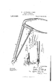
- Figure 1 is a. side elevation of the cotter pin extractor showing the cotter pin extracting bar partly extended to hook into the eye of a cotter pin.
- Fig. 2 is a top plan view of the forward end of the implement as shown in Fig. 1 and
- Fig. 3 is a bottom plan view showing the hook end of the extracting bar engaging the eye of a cotter pin and in the act of withdrawing said pin from the clevis pin and
- Fig. 4 is a sectional view of the end of the tool on the line H of Fig. 2.
- 1 designates the stationary body portion of the tool which consists preferably of a round bar the forward end of which is flattened and turned to form a handle 2 which is gripped by the hand in the manipulation of the device.
- the front end of the said bar 1 is curved downwardly as at 5 to bring it To meet this requirement-the portion 5 ofsaid bar 1 has an opening 7 therein through which the pin extracting bar 6 slides in the manipulation of the implement.
- the supporting bar 1 remains stationary while the extracting bar 6 is operated.
- the forward end of said bar 1 is also extended upwardly as at 3 and has a recess surrounded by a corrugated portion 4 which abuts against a side of the clevis or other surface in positioning the implement for extracting the cotter pins.
- the said face 4 is provided with a rough surface or corrugations which enable it to avoid slipping on the surface of the clevis when brought in contact therewith and operated.
- the said end 3 of the bar 1 is also provided as before stated with the recess 8 which is of U-shape and into which the cotter pins are drawn in removing the same.
- the forward end of the cotter extracting bar 6 is reduced in diameter and turned up to form a hook 9 which enters the eye of the cotter pin 10 as shown in Fig.
- the said extracting bar 6 is being drawn rearwardly to withdraw the cotter pin 10 from the clevis pin 11 which holds the clevis 12.
- the cotter pin extracting bar 6 is connected to a handle 13 by a pivot pin 14 and a clevis 15 and may be adjusted to shorten or extend the length of said bar 6 by adjusting lock nuts 17.
- the handle or lever 13 is fulcrumed to the main body or bar 1 near the handle 2 by a pivot pin 18.
- the bar 6 In manipulating the implement the bar 6 is extended to the desired point to enter the eye of the cotter pin to be removed.
- the cotter pins are in more or less inaccessible places and it is required to extend the rod 6 to a greater length than in cases where the cotter pins are more exposed.
- the hook end 9 enters the eye of the pin while the handle portion 2 is gripped by the hand with the fingers extended over the pivotal handle 13.
- the pin extracting bar 6 is likewise drawn rearwardly with the result end terminating in an enlarged portion having a recess therein and an opening therein below said recess therein, a pin extracting bar supported and movable in said opening, said bar having its end formed in a hook to enter the eye of a cotter pin and to draw the cotter pin into the recess in the end of said stationary supporting bar in extracting said In testimony whereof we affix our signatures.
Landscapes
- Engineering & Computer Science (AREA)
- Mechanical Engineering (AREA)
- Hand Tools For Fitting Together And Separating, Or Other Hand Tools (AREA)
Description
WITNESS I w 48W W. E. AYLOR AND M. A. McGUFF.
CUTTER PIN EXTRACTOR.
APPLICATION FILED AUG. I4. 1918.
1,319,829. Patented Oct. 28,1919.
neutral) STATES PATENT onrron.
WILLIAM E. AYLOR AND MATTHEW A. McG-UFF, F DAYTON, OHIO.
co'r'rnn rm ExTnAo'roR.
Specification of Letters Patent.
Patented Oct. 28, 1919.
Application filed August 14, 1918. Serial No. 249,773.
To aZZ w/wm it may concern Be it known that we, WILLIAM EIAYLORI' and MATTHEW A. MCGUFF, citizens of the United States, residing at Dayton, in the county of Montgomery and State of Ohio, have invented certain new and useful Improvements in Cotter- Pin Extractors, of which the following is a specification.
Our invention comprises a tool or implement for extracting cotter pins employed for holding the clevis pins in airship construction. In airship construction all the parts necessarily have to be unitedand the airship completed inall its details in order that it may be subjected to tests or actual flights. These tests are carried on for a certain time in order to ascertain whether the airship is in a satisfactory and safe con dition. After this is determined by the tests the entire aircraft is dismantled and all the parts disconnected for packing and shipping the same to the point of ultimate use. This dismantling or taking apart of the airships has heretofore entailed considerable time owing to it being necessary to remove a great many cotter pins which hold the clevis pins used to unite the clevises. It is therefore the object of the present invention to provide a specially constructed tool designed for the express purpose of removing these cotter pins quickly and with comparative ease. The accompanying drawings illustrate our improved cotter pin extractor and to these reference will now be made in general terms. Figure 1 is a. side elevation of the cotter pin extractor showing the cotter pin extracting bar partly extended to hook into the eye of a cotter pin. Fig. 2 is a top plan view of the forward end of the implement as shown in Fig. 1 and Fig. 3 is a bottom plan view showing the hook end of the extracting bar engaging the eye of a cotter pin and in the act of withdrawing said pin from the clevis pin and Fig. 4 is a sectional view of the end of the tool on the line H of Fig. 2.
In a detail description of the invention similar reference characters indicate corresponding parts in the several illustrations, 1 designates the stationary body portion of the tool which consists preferably of a round bar the forward end of which is flattened and turned to form a handle 2 which is gripped by the hand in the manipulation of the device. The front end of the said bar 1 is curved downwardly as at 5 to bring it To meet this requirement-the portion 5 ofsaid bar 1 has an opening 7 therein through which the pin extracting bar 6 slides in the manipulation of the implement. The supporting bar 1 remains stationary while the extracting bar 6 is operated. The forward end of said bar 1 is also extended upwardly as at 3 and has a recess surrounded by a corrugated portion 4 which abuts against a side of the clevis or other surface in positioning the implement for extracting the cotter pins. The said face 4: is provided with a rough surface or corrugations which enable it to avoid slipping on the surface of the clevis when brought in contact therewith and operated. The said end 3 of the bar 1 is also provided as before stated with the recess 8 which is of U-shape and into which the cotter pins are drawn in removing the same. The forward end of the cotter extracting bar 6 is reduced in diameter and turned up to form a hook 9 which enters the eye of the cotter pin 10 as shown in Fig. .3. In this illustration the said extracting bar 6 is being drawn rearwardly to withdraw the cotter pin 10 from the clevis pin 11 which holds the clevis 12. The cotter pin extracting bar 6 is connected to a handle 13 by a pivot pin 14 and a clevis 15 and may be adjusted to shorten or extend the length of said bar 6 by adjusting lock nuts 17. The handle or lever 13 is fulcrumed to the main body or bar 1 near the handle 2 by a pivot pin 18. In manipulating the implement the bar 6 is extended to the desired point to enter the eye of the cotter pin to be removed. In some cases the cotter pins are in more or less inaccessible places and it is required to extend the rod 6 to a greater length than in cases where the cotter pins are more exposed. The hook end 9 enters the eye of the pin while the handle portion 2 is gripped by the hand with the fingers extended over the pivotal handle 13. By drawing rearwardly on the handle 13 the pin extracting bar 6 is likewise drawn rearwardly with the result end terminating in an enlarged portion having a recess therein and an opening therein below said recess therein, a pin extracting bar supported and movable in said opening, said bar having its end formed in a hook to enter the eye of a cotter pin and to draw the cotter pin into the recess in the end of said stationary supporting bar in extracting said In testimony whereof we affix our signatures.
WILLIAM E. AYLOR. MATTHEW A. MCGUFF.
Copies of this patent may be obtained for five cents each, by addressing the, Commissioner of Patents, Washington, .D. (1..
Publications (1)
| Publication Number | Publication Date |
|---|---|
| US1319829A true US1319829A (en) | 1919-10-28 |
Family
ID=3387300
Family Applications (1)
| Application Number | Title | Priority Date | Filing Date |
|---|---|---|---|
| US1319829D Expired - Lifetime US1319829A (en) | Cotter-pin extiiactor |
Country Status (1)
| Country | Link |
|---|---|
| US (1) | US1319829A (en) |
Cited By (3)
| Publication number | Priority date | Publication date | Assignee | Title |
|---|---|---|---|---|
| US3822468A (en) * | 1972-03-22 | 1974-07-09 | Merit Metal Prod Corp | Tool for removal of deterrent spring clip |
| US6516505B1 (en) * | 2001-08-14 | 2003-02-11 | James D. Taylor | Tool for installing removable fasteners |
| CN108673414A (en) * | 2018-04-27 | 2018-10-19 | 国家电网公司 | A kind of R types spring catch extracting tool |
-
0
- US US1319829D patent/US1319829A/en not_active Expired - Lifetime
Cited By (3)
| Publication number | Priority date | Publication date | Assignee | Title |
|---|---|---|---|---|
| US3822468A (en) * | 1972-03-22 | 1974-07-09 | Merit Metal Prod Corp | Tool for removal of deterrent spring clip |
| US6516505B1 (en) * | 2001-08-14 | 2003-02-11 | James D. Taylor | Tool for installing removable fasteners |
| CN108673414A (en) * | 2018-04-27 | 2018-10-19 | 国家电网公司 | A kind of R types spring catch extracting tool |
Similar Documents
| Publication | Publication Date | Title |
|---|---|---|
| US1319829A (en) | Cotter-pin extiiactor | |
| US1885377A (en) | Weeding implement | |
| US1316409A (en) | Cotteb-pin-extractihg tool | |
| US1987399A (en) | Nut cracker | |
| US2185552A (en) | Weed puller | |
| US1806339A (en) | Expanding device | |
| US3797095A (en) | Bearing puller | |
| US2058072A (en) | Nut recracker | |
| US1961246A (en) | Screw driver | |
| US943322A (en) | Flight-extractor. | |
| US1610969A (en) | Cotter-pin extractor | |
| US1725169A (en) | Gear and wheel puller | |
| US1812682A (en) | Cotter key puller | |
| US1363934A (en) | Journal-box or flue puller | |
| US1709683A (en) | Post or stake puller | |
| US1444280A (en) | Bearing-sleeve puller | |
| US317318A (en) | Cartridge implement | |
| US1336938A (en) | Cotter-extractor | |
| US1576534A (en) | Bearing-sleeve puller | |
| US1876907A (en) | Weed extractor | |
| US1648106A (en) | Clamping gear puller | |
| US1436589A (en) | Cotter-pin puller | |
| US1422201A (en) | Cotter-pin puller | |
| US2154867A (en) | Bushing puller | |
| US1394963A (en) | Gear-puller attachment |