US1291069A - Printing-press. - Google Patents
Printing-press. Download PDFInfo
- Publication number
- US1291069A US1291069A US15878517A US15878517A US1291069A US 1291069 A US1291069 A US 1291069A US 15878517 A US15878517 A US 15878517A US 15878517 A US15878517 A US 15878517A US 1291069 A US1291069 A US 1291069A
- Authority
- US
- United States
- Prior art keywords
- roller
- crank
- bed
- disk
- rollers
- Prior art date
- Legal status (The legal status is an assumption and is not a legal conclusion. Google has not performed a legal analysis and makes no representation as to the accuracy of the status listed.)
- Expired - Lifetime
Links
- 238000010276 construction Methods 0.000 description 8
- 230000000694 effects Effects 0.000 description 8
- 238000013459 approach Methods 0.000 description 4
- 239000002184 metal Substances 0.000 description 2
- 230000002093 peripheral effect Effects 0.000 description 2
- 230000015572 biosynthetic process Effects 0.000 description 1
- 230000006870 function Effects 0.000 description 1
Images

Classifications
-
- B—PERFORMING OPERATIONS; TRANSPORTING
- B41—PRINTING; LINING MACHINES; TYPEWRITERS; STAMPS
- B41F—PRINTING MACHINES OR PRESSES
- B41F3/00—Cylinder presses, i.e. presses essentially comprising at least one cylinder co-operating with at least one flat type-bed
- B41F3/46—Details
- B41F3/58—Driving, synchronising, or control gear
-
- Y—GENERAL TAGGING OF NEW TECHNOLOGICAL DEVELOPMENTS; GENERAL TAGGING OF CROSS-SECTIONAL TECHNOLOGIES SPANNING OVER SEVERAL SECTIONS OF THE IPC; TECHNICAL SUBJECTS COVERED BY FORMER USPC CROSS-REFERENCE ART COLLECTIONS [XRACs] AND DIGESTS
- Y10—TECHNICAL SUBJECTS COVERED BY FORMER USPC
- Y10T—TECHNICAL SUBJECTS COVERED BY FORMER US CLASSIFICATION
- Y10T74/00—Machine element or mechanism
- Y10T74/18—Mechanical movements
- Y10T74/18056—Rotary to or from reciprocating or oscillating
- Y10T74/18072—Reciprocating carriage motions
Definitions
- ROBERT MIEI-ILE OF CHICAGO
- ILLINOIS ILLINOIS
- My invention relates to flat bed printing presses.
- my invention is use ful in mechanism for efi'ecting reciprocation of the bed of such a press that is inclusive of gates for forming slots which receive the bed motion roller mechanism that reverses the motion of the bed.
- My invention relates particularly to the roller mechanism and, in one embodiment thereof,
- roller mechanism employs two rollers for engaging opposite slot sides.
- parts of the press may be more closely approached, and by means of another feature of the invention bearing support for the roller mechanism is materially increased, to avoid undue wear and cutting or scoring action.
- Figure 1 is a rear side view illustrating a portion of a printing press embodying my invention
- Fig. 2 is a view on line 2 -2 of Fig. 6
- Fig. 3 is a sectional plan view showing novel parts of the press
- Fig. 4 is a view of a part of the mechanism as shown in Fig. 3 illustrating the gate at one end of the bed closed in full lines and open in dotted lines
- Fig. 5 is a view of the gate at the other end of the bed shown open in full lines and closed in dotted lines
- Fig. 6 is a partial View on line 6-6 of Fig. 1
- Fig. 7 illustrates another form.
- the bed 2 is of the usual flat bed reciprocating type. Fixedly secured tothe under side of the bed 2 or otherwise connected therewith in a manner to reciprocate it is a rack frame 1, which is provided with Specification of Letters Patent.
- reversing crank 34 is fixed to the said gear and is provided with large anti-friction rollers 35, 35 roller 35' being engageable with slot sides 40, 40 while roller 35 is engageable with slot sides 39, 39
- the driving gear 5 is secured to the bed motion shaft 6, which extends outside the type bed or press frame, and receives motion from any suitable drive gear, which it is not necessary to describe herein, as it has no bearing on the present invention. 7
- the driving gear 5 is raised and lowered (thus alternately engaging with the upper and lower racks 3 and 4) by means of the bed motion rocker frame 20 which consists of the fulcrum extensions 16 and 17 which have bearing in the standard 18 and the side frame; a bearing 20 (formed on the main body 20 in which is journaled the bed motion shaft 6; an arm 21 (extending from the main body 20 and the bearing 20) which has a stud and anti-friction roller 22 in the cam groove 23 of the bed motion cam 24 on the cam shaft 25.
- the shaft 25 receives motion in the usual way from a regular train of gears, which it is unnecessary to show in order to; understand the present improvement.
- At one end of the rack frame 1 is hinged a gate28.
- Said gate is hinged to upper and lower lugs a by studs 5.
- the gate is formed with an arm 29 which carries a roller 30.
- Said gate is also provided with a lug which carries a roller 32. These rollers are positioned to cooperate with facecams 31 and 33 respectively, which cams are mounted on brackets '1' of the framework of the press.
- the gate 28? at the other end of the bed is hinged to upper and lower lugs a by studs 5
- This gate 28 has an arm 29 carryinga roller 30
- a roller 32 is mounted directly on the gate 28
- These rollers 30 and 32 cooperate with similar face cams 31 and 33 carried by the brackets 1.
- the gates 28 and 28 will be oscillated on their supporting lugs.
- the type bed is at the stop at the end of the printing stroke, the driving gear 5 being disengaged from both racks 3 and 4.
- the roller 32 against the cam 33 is holding the gate 28 in its closed position, the roller 30 against the cam 31 preventing the working face 39 of the gate 28 from swinging in too close to the rack frame 1.
- driving gear 5 rotates in the direction indicated by the arrow in Fig. 1, the type bed 2 and the rack frame 1, see Fig.
- the roller 32 moves to the right on the nonprinting stroke, the roller 32 passes over the portion 0 of the cam 33 and the roller 30 passes over the portion (Z of the cam 31, thus positively opening the gate 28 and releasing the said crank stud rollers 35, 35 At the same time, the crank stud rollers 35, 35 are so released, the driving gear 5 which has been lowered by the movement of the bed motion rocker frame 20, engages lower rack 4 and drives the type bed on the non-printing stroke.
- the roller 30 acting against the portion 6 of the cam 31 serves to positively hold the gate 28 open, as shown in dotted construction in Fig. 4.
- the set screw 8 abutting against the gate frame 28, limits the movement of the said gate and prevents the rollers 30 from leaving the guide surface 0.
- roller 32 passes over the portion 7 of the cam 33 and roller 30 passes over the portion 9 of the cam 31 thus positively opening the gate 28 and releasing the said crank stud rollers 35, 35
- the crank stud rollers 35, 35 are so released the driving gear 5 which has been raised by the movement of the bed motion rocker frame 20 engages the upper rack 3 and drives the type bed on the printing stroke.
- the roller 30 acting against the portion 71, of the cam 31, serves to positively hold the gate 28 open, as shown in Figs. 3 and 5.
- The. set screw 8 abuttingagainst the gate frame 28 limits the movement of the said gate, and prevents the rollers 30 from leaving the guide surface 71.
- the roller 32 passes over the portion 0 of the cam 33 and roller 30 passes over the portion (Z of cam 31, thus positively closing the gate 28 as shown in Figs. 3 and 4, and engaging the crank stud rollers 35, 35 in the slot formed by the working surface 39 of the gate 28, and the shoulder 40 of the rack frame 1.
- the crank stud rollers 35, 35 are so engaged, the driving gear 5 is lowered by the movement of the bed motion rocker frame 20 and thus disengaged from upper rack 3.
- the type bed is now controlled by the crank stud rollers 35, 35 in the slot formed as above, and comes to a full stop in the position shown in Figs. 1 and 3.
- slot sides 40, 40 co5perate with one roller 35 and the slot sides 39,
- crank 34 has a crank disk 41, in lieu of a crank pin, for supporting a roller 35.
- the disk approaches the center of the gear 5 more closelv than would the pin, on which account the mass of metal uniting the disk and base of the crank may be distributed as illustrated and is of such strength that the crank disk may occupv a plane of rotation closer to the gear 5 than would the pin, this arrangement permitting the closer approach of the frame 1 to the gear 5.
- roller bearings 42 preferably cylindrical, between the roller 35 and the crank disk 41.
- I employ two roller supporting rings 43 and 44 which are received in annular face grooves compositely formed in the crank disk 41 and the roller 35 whereby said crank disk and roller are maintained in the same plane. These rings are held together by means of screws 45 which are distributed around the crank disk at intervals. The annular grooves in which the rings 43 and 44 are received are co-axial with the disk 41. A ring 46 intervenes between the heads of the screws 45 and the ring 43.
- the groove that receives the ring 44 partially intervenes between the base of the crank 34 and the disk 41, the metal of the crank base being continued at 47 to form a circular wall for the groove that receives the ring 44 to prevent dislodgment of this ring. Because of this construction the ring 44 is desirably formed in two halves to permit of its assembly, the ends of these halves meeting along the plane indicated by the dotted lines 48 in Fig. 2.
- crank disk 41 has a crank pin continuation 49 preferably co-axial therewith and in order that the crank pin 49 may be made as long as possible within the limits permissible-by the structure, the crank disk 41 is dished adjacent the roller 35 whereby the base of the crank pin 49 is situated laterally of the roller 35 a considerable distance from the plane of the peripheral portion of this roller.
- the dished formation in the disk 41 is circumferentially enlarged to afford an annular space surrounding the pin 49 and co-axial therewith and of a size sufficient to receive the hub 50 of the roller 35 "that projects laterally of this roller toward roller 35.
- the outer end face of the hub 50 engages the bottom of the dished recess in the disk 41, being held in this engagement by means of the cap plate 51 that is attached to the outer end of the crank pin 49.
- a portion of the roller structure 35 is thus surrounded by the roller 35 to permit of the elongation of the bearing 49 for the roller 35 practically to offset any tendency of the slot sides 39, 39 to twist or slant the axis of the roller 35 from normality, a result which prevents the outer end of the hub 50 of theroller 35 from cutting into the crank pin 49 at the base of the latter.
- the bore of the hub 50 is also kept smooth.
- the axis of the roller is especially liable to be slanted or twisted from normality because'of the springy yield of the crank pin supporting this roller and the springy yield of the closed gate 28 or 28 engaging the roller, a result which is enhanced because the bearing surface 39 or 39 of the gate face is offset from the gate pivot Z) or 5 such offset being required to permit of timely clearance of the gates from the roller.
- the hub 50 is extended clear through the bore of the roller 35 and contacts with the base of the crank 34, being held in such contact by the cap plate 51 screwed upon the outer end of the crank pin 49.
- the hub 50 constitutes the bearing for the roller 35, no roller bearings being needed between this hub and roller bearings for said roller.
- the hub 50 of the roller 35 in the construction of Fig. 7 is extended preferably through the bore of the roller 35 toward the crank 34, the hub 52 of the roller 35 is projected laterally of this roller into a dishing recess formed in roller 35 to increase the length of the hearing 50 upon which the roller 35 turns.
- a portion of each roller 35, 35 is surrounded by the other roller to increase the lateral extent of the bearings for both of these rollers.
- a flat bed printing press including a reciprocable bed; an actuating gear wheel; a rack structure in actuating relation to the bed and cooperating with the gear wheel to effect travel of the bed; a reversing crank carried by said gear wheel; two rollers carried upon the reversing crank; and a slotted structure cooperating with said rollers and having offset roller engaging slot sides, the roller farther from the crank having a hub extending laterally therefrom toward the crank.
- a flat bed printing press including a reciprocable bed; an actuating gear wheel; a rack structure in actuating relation to the bed and cooperating with the gear wheel to effect travel of the bed; a reversing crank carried by said gear wheel; two rollers carried upon the reversing crank; and a slotted structure cooperating with said rollers and having ofiset roller engaging slot sides, the roller farther from the crank having a hub extending laterally therefrom toward the crank and surrounded by the other roller.
- a flat bed printing press including a reciprocable bed; an actuating gear wheel; a rack structure in actuating relation to the bed and cooperating with the gear wheel to efieet travel of the bed; a reversing crank carried by said gear wheel; two rollers carried upon the reversing crank; and a slotted structure cooperating with said rollers and having offset roller engaging slot sides, the crank carrying a disk for supporting the roller nearer the crank and the disk carrying a pin for supporting the other roller.
- a flat bed printing press including a reciprocable bed; an actuating gear wheel; a rack structure in actuating relation to the bed and cooperating with the gear wheel to effect travel of the bed; a reversing crank carried by said gear wheel; two rollers carried upon the reversing crank; a slotted structure cooperating with said rollers and having offset roller engaging slot sides, the crank carrying a disk for supporting the roller nearer the crank and the disk carrying a pin for supporting the other roller; and bearing rollers interposed between said disk and the roller supported by the disk.
- a flat bed printing press including a reciprocable bed; an actuating gear wheel; a rack structure in actuating relation to the bed and cooperating with the gear wheel to effect travel of the bed; a reversing crank carried by said gear wheel; two rollers carried upon the reversing crank; and a slotted structure cooperating with said rollers and having offset roller engaging slot sides; the crank carrying a'disk for supporting the roller nearer the crank and the disk carrying a pin for supporting the other roller, the first aforesaid roller having a recess therein which surrounds said pin while the second aforesaid roller has a hub surrounding said pin and projecting into said recess where it is surrounded by the first roller.
- a fiat bed printing press including a reciprocable bed; an actuating gear wheel; a rack structure in actuating relation to the bed and cooperating with the gear wheel to effect travel of the bed; a reversing crank carried by said gear wheel; two rollers carried upon the reversing crank; a slotted structure cooperating with said rollers and having offset roller engaging slot sides, the crank carrying a disk for supporting the roller nearer the crank and the disk carrying a pin for supporting the other roller; and bearing rollers interposed between said disk and the roller supported by the disk, the first aforesaid roller having a recess therein which surrounds said pin while the second aforesaid roller has a hub surrounding said pin and projecting into said recess where it is surrounded by the first roller.
- A- flat bed printing press including a reciprocable bed; an actuating gear wheel; a rack structure in actuating relation to the bed and cooperating with the gear wheel to effect travel of the bed; a reversing crank carried by said gear wheel; two rollers carried upon the reversing crank; a slotted structure cooperating with said rollers and having ofiset roller engaging slot sides; and a crank pinfor supporting the roller that is farther from the crank; this roller having a hub portion extending toward the crank bed and cooperating with the gear wheel to effect travel of the bed; a reversing crank carried by said gear wheel; a roller; a crank disk upon said crank and closely approached to said gear wheel and upon which disk said roller is mounted to turn; and bearing rollers interposed between said disk and the roller disposed about the disk.
- a fiat bed printing press including a reciprocable bed; an actuating gear wheel; a rack structure in actuating relation to the bed and cooperating with the gear wheel to efiect travel of the bed; a reversing crank carried by said gear Wheel; a roller; a crank disk upon said crank and closely approached to said gear wheel and upon which disk said roller is mounted to turn; cylindrical bearing rollers interposed between said'disk and.
- the roller disposed about the disk; and supporting rings for said bearing rollers, the base of the crank being extended to position one of said rings, which is split, between the crank base and said disk.
- a fiat bed printing press including a to said gear wheel and upon which disk said roller is mounted to turn; cylindrical bearing rollers interposed between said disk and the roller disposed about the disk; and supporting rings for said bearing rollers, the ring near the crank being split to permit of its assembly.
Landscapes
- Engineering & Computer Science (AREA)
- Mechanical Engineering (AREA)
- Transmission Devices (AREA)
Description
R, MIEHLE.
PRINTING PRESS.
APPLICATION FILED MAR. 31, 1911.
Patented Jan. 14, 1919.
2 SHEETS-SHEET I.
. I N VEN TOR. E02; @6 25 @5 4 W77 A TTORNE Y UNITED STATES trim onnion.
ROBERT MIEI-ILE, OF CHICAGO, ILLINOIS.
PRINTING-PRESS.
Application filed March 31, 1917.
My invention relates to flat bed printing presses. In particular my invention is use ful in mechanism for efi'ecting reciprocation of the bed of such a press that is inclusive of gates for forming slots which receive the bed motion roller mechanism that reverses the motion of the bed. My invention relates particularly to the roller mechanism and, in one embodiment thereof,
is an improvement upon the single roller structure in apparatus of this class disclosed in my United States Letters Paten-t 1,093,346, dated April 14, 1914. However, in the preferred embodiment of my invention the roller mechanism employs two rollers for engaging opposite slot sides. By means of one feature of the invention parts of the press may be more closely approached, and by means of another feature of the invention bearing support for the roller mechanism is materially increased, to avoid undue wear and cutting or scoring action.
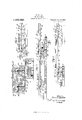
I will explain my invention more fully by reference to the accompanying drawings showing one embodiment thereof in a cylinder fiat bed printing press and in which Figure 1 is a rear side view illustrating a portion of a printing press embodying my invention; Fig. 2 is a view on line 2 -2 of Fig. 6; Fig. 3 is a sectional plan view showing novel parts of the press; Fig. 4 is a view of a part of the mechanism as shown in Fig. 3 illustrating the gate at one end of the bed closed in full lines and open in dotted lines; Fig. 5 is a view of the gate at the other end of the bed shown open in full lines and closed in dotted lines; Fig. 6 is a partial View on line 6-6 of Fig. 1; and Fig. 7 illustrates another form.
Like parts are indicated by similar characters of reference throughout the different figures.
In the preferred embodiment as shown, the bed 2 is of the usual flat bed reciprocating type. Fixedly secured tothe under side of the bed 2 or otherwise connected therewith in a manner to reciprocate it is a rack frame 1, which is provided with Specification of Letters Patent.
Patented Jan. 14, 1919.
Serial No. 158,785.
upper and lower racks 3 and 4 with which the driving gear 5 alternately engages.
reversing crank 34 is fixed to the said gear and is provided with large anti-friction rollers 35, 35 roller 35' being engageable with slot sides 40, 40 while roller 35 is engageable with slot sides 39, 39 The driving gear 5 is secured to the bed motion shaft 6, which extends outside the type bed or press frame, and receives motion from any suitable drive gear, which it is not necessary to describe herein, as it has no bearing on the present invention. 7
The driving gear 5 is raised and lowered (thus alternately engaging with the upper and lower racks 3 and 4) by means of the bed motion rocker frame 20 which consists of the fulcrum extensions 16 and 17 which have bearing in the standard 18 and the side frame; a bearing 20 (formed on the main body 20 in which is journaled the bed motion shaft 6; an arm 21 (extending from the main body 20 and the bearing 20) which has a stud and anti-friction roller 22 in the cam groove 23 of the bed motion cam 24 on the cam shaft 25. The shaft 25 receives motion in the usual way from a regular train of gears, which it is unnecessary to show in order to; understand the present improvement. At one end of the rack frame 1 is hinged a gate28. Said gate is hinged to upper and lower lugs a by studs 5. The gate is formed with an arm 29 which carries a roller 30. Said gate is also provided with a lug which carries a roller 32. These rollers are positioned to cooperate with facecams 31 and 33 respectively, which cams are mounted on brackets '1' of the framework of the press. Likewise the gate 28? at the other end of the bed is hinged to upper and lower lugs a by studs 5 This gate 28 has an arm 29 carryinga roller 30 A roller 32 is mounted directly on the gate 28 These rollers 30 and 32 cooperate with similar face cams 31 and 33 carried by the brackets 1. As the bed is reciprocated, the gates 28 and 28 will be oscillated on their supporting lugs.
The Working faces 39 and 39 of the gates 28 and 28 together with the shoulders 40 and 40 of the rack frame 1, form the usual slots in which my crank stud rollers 35, 35 on reversing crank 34, operate to retard, stop and reverse the movement of the type bed, in the following manner: As shown in Figs. 1 and 3, the type bed is at the stop at the end of the printing stroke, the driving gear 5 being disengaged from both racks 3 and 4. Referring to Fig. 3, the roller 32 against the cam 33 is holding the gate 28 in its closed position, the roller 30 against the cam 31 preventing the working face 39 of the gate 28 from swinging in too close to the rack frame 1. As driving gear 5 rotates in the direction indicated by the arrow in Fig. 1, the type bed 2 and the rack frame 1, see Fig. 4, moving to the right on the nonprinting stroke, the roller 32 passes over the portion 0 of the cam 33 and the roller 30 passes over the portion (Z of the cam 31, thus positively opening the gate 28 and releasing the said crank stud rollers 35, 35 At the same time, the crank stud rollers 35, 35 are so released, the driving gear 5 which has been lowered by the movement of the bed motion rocker frame 20, engages lower rack 4 and drives the type bed on the non-printing stroke. The roller 30 acting against the portion 6 of the cam 31, serves to positively hold the gate 28 open, as shown in dotted construction in Fig. 4. The set screw 8 abutting against the gate frame 28, limits the movement of the said gate and prevents the rollers 30 from leaving the guide surface 0.
Near the end of the non-printing stroke, as shown in Fig. 5, the roller 32 passes over the portion of the cam 33 and the roller 30 passes over the portion 9' of the cam 31 thus positively closing gate 28 as shown in dotted construction in Fig. 5. The closing of the gate engages the crank stud rollers 35, 35 on reversing crank 34 in the slot formed by the working surface 39 and the shoulder 40 of the rack frame 1. At the same time, the said crank stud rollers 35, 35 are so engaged, the driving gear 5 is raised by the movement of the bed motion rocker frame 20 thus being disengaged from lower rack 4. The movement of the type bed is now controlled by the crank stud rollers 35, 35 in the slot formed as above, and comes to a full stop at the end of the non-printing stroke. As driving gear 5 continuesto rotate, and the type bed and rack frame move to the left on the printing stroke, the roller 32 passes over the portion 7 of the cam 33 and roller 30 passes over the portion 9 of the cam 31 thus positively opening the gate 28 and releasing the said crank stud rollers 35, 35 At the same time the crank stud rollers 35, 35 are so released the driving gear 5 which has been raised by the movement of the bed motion rocker frame 20 engages the upper rack 3 and drives the type bed on the printing stroke. The roller 30 acting against the portion 71, of the cam 31, serves to positively hold the gate 28 open, as shown in Figs. 3 and 5. The. set screw 8 abuttingagainst the gate frame 28 limits the movement of the said gate, and prevents the rollers 30 from leaving the guide surface 71. Near the end of the printing stroke, the roller 32 passes over the portion 0 of the cam 33 and roller 30 passes over the portion (Z of cam 31, thus positively closing the gate 28 as shown in Figs. 3 and 4, and engaging the crank stud rollers 35, 35 in the slot formed by the working surface 39 of the gate 28, and the shoulder 40 of the rack frame 1. At the same time, the crank stud rollers 35, 35 are so engaged, the driving gear 5 is lowered by the movement of the bed motion rocker frame 20 and thus disengaged from upper rack 3. The type bed is now controlled by the crank stud rollers 35, 35 in the slot formed as above, and comes to a full stop in the position shown in Figs. 1 and 3.
As set forth, the slot sides 40, 40 co5perate with one roller 35 and the slot sides 39,
'39 cotiperate with another roller 35 the slot sides 40, 40 being offset with respect to the operating positions of the slot sides 39, 39 It is one of the objects of my invention to effect closer approach between the operating gear 5 and the roller 35 to permit of the closer approach of the gate and slot structure and the gear 5 and the racks cooperating therewith, and this feature of invention I claim broadly whether the roller 35 is limited to coiiperation with the slot sides 40, 40 as I prefer, or is elongated to coiiperate with both sets of slot sides 40, 40 and 39, 39 as set forth in my said Patent 1,093,346. The slot sides 39, 39 when positioned to function, are offset with respect to the slot sides 40, 40 and on this account the roller is subjected to a twisting or straining movement which I guardagainst by another feature of my invention. Referring first to Figs. 2 and 6, the crank 34 has a crank disk 41, in lieu of a crank pin, for supporting a roller 35. The disk approaches the center of the gear 5 more closelv than would the pin, on which account the mass of metal uniting the disk and base of the crank may be distributed as illustrated and is of such strength that the crank disk may occupv a plane of rotation closer to the gear 5 than would the pin, this arrangement permitting the closer approach of the frame 1 to the gear 5. Because of the increased peripheral length of the element 41 upon which the roller 35' is mounted to turn I interpose roller bearings 42, preferably cylindrical, between the roller 35 and the crank disk 41. In this roller bearing construction I employ two roller supporting rings 43 and 44 which are received in annular face grooves compositely formed in the crank disk 41 and the roller 35 whereby said crank disk and roller are maintained in the same plane. These rings are held together by means of screws 45 which are distributed around the crank disk at intervals. The annular grooves in which the rings 43 and 44 are received are co-axial with the disk 41. A ring 46 intervenes between the heads of the screws 45 and the ring 43. The groove that receives the ring 44 partially intervenes between the base of the crank 34 and the disk 41, the metal of the crank base being continued at 47 to form a circular wall for the groove that receives the ring 44 to prevent dislodgment of this ring. Because of this construction the ring 44 is desirably formed in two halves to permit of its assembly, the ends of these halves meeting along the plane indicated by the dotted lines 48 in Fig. 2.
Where an extra roller 35 is employed to co-act with the slotted sides 39, 39 the crank disk 41 has a crank pin continuation 49 preferably co-axial therewith and in order that the crank pin 49 may be made as long as possible within the limits permissible-by the structure, the crank disk 41 is dished adjacent the roller 35 whereby the base of the crank pin 49 is situated laterally of the roller 35 a considerable distance from the plane of the peripheral portion of this roller. The dished formation in the disk 41 is circumferentially enlarged to afford an annular space surrounding the pin 49 and co-axial therewith and of a size sufficient to receive the hub 50 of the roller 35 "that projects laterally of this roller toward roller 35. The outer end face of the hub 50 engages the bottom of the dished recess in the disk 41, being held in this engagement by means of the cap plate 51 that is attached to the outer end of the crank pin 49. A portion of the roller structure 35 is thus surrounded by the roller 35 to permit of the elongation of the bearing 49 for the roller 35 practically to offset any tendency of the slot sides 39, 39 to twist or slant the axis of the roller 35 from normality, a result which prevents the outer end of the hub 50 of theroller 35 from cutting into the crank pin 49 at the base of the latter. The bore of the hub 50 is also kept smooth. In the structure of my aforesaid patent the axis of the roller is especially liable to be slanted or twisted from normality because'of the springy yield of the crank pin supporting this roller and the springy yield of the closed gate 28 or 28 engaging the roller, a result which is enhanced because the bearing surface 39 or 39 of the gate face is offset from the gate pivot Z) or 5 such offset being required to permit of timely clearance of the gates from the roller.
In the construction shown in Fig. 7 the hub 50 is extended clear through the bore of the roller 35 and contacts with the base of the crank 34, being held in such contact by the cap plate 51 screwed upon the outer end of the crank pin 49. The hub 50 constitutes the bearing for the roller 35, no roller bearings being needed between this hub and roller bearings for said roller. -While the hub 50 of the roller 35 in the construction of Fig. 7 is extended preferably through the bore of the roller 35 toward the crank 34, the hub 52 of the roller 35 is projected laterally of this roller into a dishing recess formed in roller 35 to increase the length of the hearing 50 upon which the roller 35 turns. In the construction shown in Fig. 7 therefore, a portion of each roller 35, 35 is surrounded by the other roller to increase the lateral extent of the bearings for both of these rollers.
While I have herein'shown and particularly described the preferred embodiment of my invention I do not wish to be limited to the precise details of construction shown as changes may readily be made without departing from the spirit of my invention, but having thus described my invention I claim as new and desire to secure by Letters Patent the following 1. A flat bed printing press including a reciprocable bed; an actuating gear wheel; a rack structure in actuating relation to the bed and cooperating with the gear wheel to effect travel of the bed; a reversing crank carried by said gear wheel; two rollers carried upon the reversing crank; and a slotted structure cooperating with said rollers and having offset roller engaging slot sides, the roller farther from the crank having a hub extending laterally therefrom toward the crank.
2. A flat bed printing press including a reciprocable bed; an actuating gear wheel; a rack structure in actuating relation to the bed and cooperating with the gear wheel to effect travel of the bed; a reversing crank carried by said gear wheel; two rollers carried upon the reversing crank; and a slotted structure cooperating with said rollers and having ofiset roller engaging slot sides, the roller farther from the crank having a hub extending laterally therefrom toward the crank and surrounded by the other roller.
3. A flat bed printing press including a reciprocable bed; an actuating gear wheel; a rack structure in actuating relation to the bed and cooperating with the gear wheel to efieet travel of the bed; a reversing crank carried by said gear wheel; two rollers carried upon the reversing crank; and a slotted structure cooperating with said rollers and having offset roller engaging slot sides, the crank carrying a disk for supporting the roller nearer the crank and the disk carrying a pin for supporting the other roller.
4. A flat bed printing press including a reciprocable bed; an actuating gear wheel; a rack structure in actuating relation to the bed and cooperating with the gear wheel to effect travel of the bed; a reversing crank carried by said gear wheel; two rollers carried upon the reversing crank; a slotted structure cooperating with said rollers and having offset roller engaging slot sides, the crank carrying a disk for supporting the roller nearer the crank and the disk carrying a pin for supporting the other roller; and bearing rollers interposed between said disk and the roller supported by the disk.
5. A flat bed printing press including a reciprocable bed; an actuating gear wheel; a rack structure in actuating relation to the bed and cooperating with the gear wheel to effect travel of the bed; a reversing crank carried by said gear wheel; two rollers carried upon the reversing crank; and a slotted structure cooperating with said rollers and having offset roller engaging slot sides; the crank carrying a'disk for supporting the roller nearer the crank and the disk carrying a pin for supporting the other roller, the first aforesaid roller having a recess therein which surrounds said pin while the second aforesaid roller has a hub surrounding said pin and projecting into said recess where it is surrounded by the first roller.
6. A fiat bed printing press including a reciprocable bed; an actuating gear wheel; a rack structure in actuating relation to the bed and cooperating with the gear wheel to effect travel of the bed; a reversing crank carried by said gear wheel; two rollers carried upon the reversing crank; a slotted structure cooperating with said rollers and having offset roller engaging slot sides, the crank carrying a disk for supporting the roller nearer the crank and the disk carrying a pin for supporting the other roller; and bearing rollers interposed between said disk and the roller supported by the disk, the first aforesaid roller having a recess therein which surrounds said pin while the second aforesaid roller has a hub surrounding said pin and projecting into said recess where it is surrounded by the first roller.
7. A- flat bed printing press including a reciprocable bed; an actuating gear wheel; a rack structure in actuating relation to the bed and cooperating with the gear wheel to effect travel of the bed; a reversing crank carried by said gear wheel; two rollers carried upon the reversing crank; a slotted structure cooperating with said rollers and having ofiset roller engaging slot sides; and a crank pinfor supporting the roller that is farther from the crank; this roller having a hub portion extending toward the crank bed and cooperating with the gear wheel to effect travel of the bed; a reversing crank carried by said gear wheel; a roller; a crank disk upon said crank and closely approached to said gear wheel and upon which disk said roller is mounted to turn; and bearing rollers interposed between said disk and the roller disposed about the disk.
10. A fiat bed printing press including a reciprocable bed; an actuating gear wheel; a rack structure in actuating relation to the bed and cooperating with the gear wheel to efiect travel of the bed; a reversing crank carried by said gear Wheel; a roller; a crank disk upon said crank and closely approached to said gear wheel and upon which disk said roller is mounted to turn; cylindrical bearing rollers interposed between said'disk and.
the roller disposed about the disk; and supporting rings for said bearing rollers, the base of the crank being extended to position one of said rings, which is split, between the crank base and said disk.
11. A fiat bed printing press including a to said gear wheel and upon which disk said roller is mounted to turn; cylindrical bearing rollers interposed between said disk and the roller disposed about the disk; and supporting rings for said bearing rollers, the ring near the crank being split to permit of its assembly.
In witness whereof, I hereunto subscribe my name this 23rd day of March, A. D.,
ROBERT MIEHLE.
Copies of this patent may be obtained for five cents each, by addressing the .Gommissioner of Patents,
Washington, D. 0.
Priority Applications (1)
| Application Number | Priority Date | Filing Date | Title |
|---|---|---|---|
| US15878517A US1291069A (en) | 1917-03-31 | 1917-03-31 | Printing-press. |
Applications Claiming Priority (1)
| Application Number | Priority Date | Filing Date | Title |
|---|---|---|---|
| US15878517A US1291069A (en) | 1917-03-31 | 1917-03-31 | Printing-press. |
Publications (1)
| Publication Number | Publication Date |
|---|---|
| US1291069A true US1291069A (en) | 1919-01-14 |
Family
ID=3358629
Family Applications (1)
| Application Number | Title | Priority Date | Filing Date |
|---|---|---|---|
| US15878517A Expired - Lifetime US1291069A (en) | 1917-03-31 | 1917-03-31 | Printing-press. |
Country Status (1)
| Country | Link |
|---|---|
| US (1) | US1291069A (en) |
-
1917
- 1917-03-31 US US15878517A patent/US1291069A/en not_active Expired - Lifetime
Similar Documents
| Publication | Publication Date | Title |
|---|---|---|
| US1291069A (en) | Printing-press. | |
| US2340010A (en) | Variable stroke combustion engine | |
| US1695271A (en) | Web-printing machine | |
| US1627775A (en) | Driving connection between alpha rotating shaft and reciprocating piston | |
| US1859457A (en) | Eccentric cam drive | |
| US1747662A (en) | Traveling-cylinder printing press | |
| US513554A (en) | Device for operating reciprocating beds of printing-presses | |
| US603496A (en) | burnham | |
| US571089A (en) | Berthold huber | |
| US945196A (en) | Mechanical movement. | |
| US2089900A (en) | Printing press | |
| US656901A (en) | Printing-press. | |
| US2633214A (en) | Intermittent feeding device for machine tools | |
| US998859A (en) | Mechanical movement. | |
| US1198727A (en) | Mechanical movement. | |
| US549261A (en) | Andrew b | |
| US215011A (en) | Improvement in oscillating printing-presses | |
| US1601851A (en) | Platen-actuating mechanism for brick machines and the like | |
| US941639A (en) | Mechanical movement. | |
| US1603642A (en) | Printing press | |
| US1093453A (en) | Printing-press. | |
| US1099940A (en) | Carriage control for printing-presses. | |
| US2244979A (en) | Bed motion for printing presses | |
| US819716A (en) | Two-revolution cylinder printing-press. | |
| KR790001548B1 (en) | Knock out device |