US1281953A - Combined type-writing and computing machine. - Google Patents
Combined type-writing and computing machine. Download PDFInfo
- Publication number
- US1281953A US1281953A US83893014A US1914838930A US1281953A US 1281953 A US1281953 A US 1281953A US 83893014 A US83893014 A US 83893014A US 1914838930 A US1914838930 A US 1914838930A US 1281953 A US1281953 A US 1281953A
- Authority
- US
- United States
- Prior art keywords
- register
- bars
- selecting
- levers
- decimal
- Prior art date
- Legal status (The legal status is an assumption and is not a legal conclusion. Google has not performed a legal analysis and makes no representation as to the accuracy of the status listed.)
- Expired - Lifetime
Links
Images


Classifications
-
- F—MECHANICAL ENGINEERING; LIGHTING; HEATING; WEAPONS; BLASTING
- F16—ENGINEERING ELEMENTS AND UNITS; GENERAL MEASURES FOR PRODUCING AND MAINTAINING EFFECTIVE FUNCTIONING OF MACHINES OR INSTALLATIONS; THERMAL INSULATION IN GENERAL
- F16K—VALVES; TAPS; COCKS; ACTUATING-FLOATS; DEVICES FOR VENTING OR AERATING
- F16K1/00—Lift valves or globe valves, i.e. cut-off apparatus with closure members having at least a component of their opening and closing motion perpendicular to the closing faces
- F16K1/12—Lift valves or globe valves, i.e. cut-off apparatus with closure members having at least a component of their opening and closing motion perpendicular to the closing faces with streamlined valve member around which the fluid flows when the valve is opened
Definitions
- the present invention is directed chiefly to the modified or improved form of the decimal order selecting mechanism of my companion application, and it comprises a plurality of decimal order selecting dogs, one for each register, a corresponding number ofregister selectors, a common set of decimal order selecting-levers upon which the several decimal order selecting dogs operate in succession, and a set of transposing bars subject to said selectingwlever and common to the several registers.
- the register selectors serve to determine on .which register the decimal order select-ing mechanism shall be operative, and the selecting action of the latter is transmitted to the various registers, through the said common so-called transposing bars.
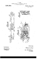
- Figure 1 is a view in side elevation with some parts broken away, showing the typewriting and computing machine.
- Fig. 2 is a plan view ofthe computing machine proper, with some parts broken away, and with some parts removed.
- Fig. 3 is a. vertical section, taken from the front toward the rear of the computing machine, approximately on the line 833 m of Fig. 2.
- Fig. 4 is a plan view with some partsbroken away, showing certain of the rear parts of the typewriter frame and typewriter carriage, and particularly illustrating the single group of upper decimal order selecting levers, and the so-called register selector or register selecting mechanism.
- Fig. 5 is a rear elevation of the parts shown in Fig. 4, some parts being broken away.
- Fig. 6 is a plan view of certain of parts shown 'in Fig. 4:, showing the same on' a larger scale.
- Fig. 7 is a vertical section taken on the line as 00 of Fig. 6.
- Fig. 8 is a section taken on the line 00 m of Fig. 7.
- Fig. 9 is a section taken on the line m w of Fig. 7.
- Fig. 10 is a detail with ome parts broken away, showing a guide for the upper ends of the lever connecting rods of the decimal order selecting mechanism, of the punctuation-space key-locking mechanism, and of the register selecting mechanism.
- Fig. 11 is a fragmentary plan view showing particularly the register bars and lower portions of the register selector and decimal order selecting mechanism, including the so-called transposing bar.
- Fig. 12 is a vertical section taken on the to Fig. 12, but illustrating difi'erent positions of the parts.
- Fig. 14 is a transverse vertical section taken approximately on the line at w of Fig. 2, some parts being removed.
- Fig. 15 is a diagrammatic view, showing the lower group of so-called selecting levers.
- Fig. 16 is a plan view of the machine
- the typewriter illustrated is a No. 5 Underwood, the construction and operation of which are well understood, and hence, for the purposes of this case, will be but briefly noted.
- the numeral 1 represents the typewriter frame
- the numeral 2 the typewriter carriage
- the numeral 3 the type bars
- the numeral 1 the character keys
- the numeral 5 the numeral keys
- the numeral 6 one of the shift keys
- the numeral 7 the spacing bail or space bar. All of these ke s are of course, spring held in their uppermost or normal positions.
- the typewriter carriage 2 has a vertically movable supplemental frame 2, that is held for parallel movements by arms 8, connected to a rock shaft 9, mounted in suitable bearings on the carriage 2.
- This supplemental frame or section of the typewriter carriage carries the customary platen or paper sup porting roller 1-1, and by depression of either of the shift keys, it will be given vertical movement, through the usual connections, not shown.
- the numeral 21 indicates the spring held line feeding lever which is connected with the platen roller 14: in the customary way, through a pawl and ratchet device, not shown), so that when the said lever is moved toward the right, the roller and paper will he moved one step, as required for the line feed.
- the typewriter carriage is under spring tension froma suitable motor spring, not shown), and moves from right toward the left, with a step by step motion, under the control of a suitable escapement that is subject to the key action.
- the numeral 26 indicates one of several upwardly spring pressed tabulating keys which operate, in the usual way, to release the typewriter carriage, for tabulating purposes; and the numerals 35, 36 and 37, (see Fig. 5), indicate respectively, the adjustable tabulating stops, the notched stop supporting bar and the cooperating scale of the tabulating mechanism.
- the computer case upon which the typewriter frame is detachably mounted, and within or upon which, most of the parts of the computing mechanism are directly or indirectly mounted, is indicated by the numeral 30', and as shown, it is of rectangular box-like form, and is provided with various bearings arid shafts and other parts, that will be particularly noted in connection with other groups of mechanisms.
- the machine herein illustrated like the machine illustrated in my companion application, is provided with several registers, but these are associated with decimal order selecting mechanism and with so-called register selecting mechanism, which as will hereinafter more clearly appear, constitute the main features of novelty of this application.
- Each register comprises a group of decimal order digit bearing wheels a, all as shown, mounted on the cross shaft (1.. On their hubs, the register wheels a have loosely mounted gears connected therewith through ratchet and oneway ball clutches, not shown, and these gears mesh with the teeth of underlying register bars, and are subject to the action of the latter, when the so-called Operating carriage of the computer is moved forward.
- the register wheels are held against accidental movements by spring pressed levers a, mounted on a transverse rod a. On the parallel cross shaft a are mounted certain.
- wheels constituting parts of the tens-carrying mechanism, two of these only appearing in the drawings, to-wit, the six-toothed wheel a, and the three-toothed wheel a.
- On another cross shaft a is mounted a series of gear segmentsor toothed arms a, which cooperate with-the parts of the shaft a in the tenscarrying action.
- the numeral keys 5 are provided with depending push bars I), that work through guide slots in the forwardly projectinrr flange of a transversely extended rectangular frame supported from the computer case 30.
- the push bars I) are pivotally connected to coupling brackets 6 which in turn are pivotally and adjustably connected to said numeral keys.
- each underlying the lower end of one of the push bars 6, said rock shafts are provided with arms I) that are adapted to be engaged by the corresponding push bars I), when the corresponding key 5 is depressed.
- unit bars 6 Mounted for vert'cal movement in the frame 6 are nine so-called unit bars 6 that are parallel to each other and extend at a right angle to the rock shafts b, or in other words, extend transversely of the computer case 30 and of the underlying register bars'c, presently to be described. As shown in Fig. 18, the ends of the unit bars 6 work in grooves 12 cut in the lower transverse end bars of the frame 11 and are I thereby held against lateral movements. Each unit bar I) is coupled to a corresponding overlying tie bar I), by a pair of bell-cranks b which are loosely mounted on fulcrum rods 7) secured to the sides of the frame If.
- a very considerable port-ion of the downward movement of the depressed numeral key is required to bring the connected push bar 7) into engagement with the corresponding rock shaft arm b; and in this connection, it may be also noted that the upper arms of the bell-cranks 6 are very short as compared with the lower arms thereof, so that a very small portion of the final downward movement of a numeral key is required to effect a considerable downward niovement of the corresponding uni-t bar.
- the especial object of this construction is to provide for very light touch and rapid successive move- 'ments of the numeral keys, by depending very largely upon the momentum of the type bars to operate the units bars I).
- rockers or cam blocks 1 For cooperation with other parts, to lock the numeral keys 5 in normal or in-operative positions under several difierent operations, a series of rockers or cam blocks 1) is provided, and these so-called rockers, as shown, are pivotally connected to the vertical front plate or side of the frame 6 and are arranged to work between a pair of steps 6 on the said frame plate. As shown in Figs. 17 and 18, there is but little play or space'between said rockers 72 and the stops I).
- each of said numeral keys is providedwith a depending lock stem that is arranged to be forced downward between the underlying two adjacent rockers, and thereby take up all play between the rockers and sto )s I).
- lock stems Z)" are prefera bly individual members that work through slots I) inthe forwardly project- .ing flange of the frame 6 and at their upper ends, are pivotally connected to coupling bracket-s b intermediately pivoted to the intermediate portions of the respective bars I), and adjustably secured thereto by opposing suitable set screws.
- the adjustable coupling brackets b and 5 permit of very accurate adjustment of the bars 6 and stems Z), in respect to th cooperating rock shaftarms 5 and rockers b, so that the precise relative times of action thereof may be properly regulated.
- the lower ends of the stems b" will be engaged -with the cooperating rockers b before the corresponding bars I) will be engaged with the cooperating rock shaft arms I).
- the long upwardly extended arms of the bell-cranks g are pivotally connected to the rear ends of forwardly extended connecting links 9 the front ends of which are attached, by slot and pin constructions g, to the free ends of upwardly extended arms 9 rigidly secured to a rock shaft 9, that is mounted in suitable bearings on the end portions of the unit bar frame If.
- This rock shaft g has a forwardly curved lock arm g, the reduced free end 9 of which is adapted to be forced between two of the rockers b but normally stands in an inoperative position below the same.
- Figs. 2 and 3 For each register comprising, as shown, nine digit bearing wheels, there is a series of eight register bars, to-wit, one for each register wheel, except the register wheel of highest order, which latter is at the extreme left. These register bars 0 extend from front toward the rear of the machine, below the unit bars I), and hence at a right angle to the latter, and are independently movable. At their forward ends, the register bars 0 have toothed rack portions that mesh with the gears a of the respective register wheels (1, and at their rear ends, said register bars are guided for longitudinal movements and are permitted limited vertical movements, by a guide comb or slotted plate 0 that is rigidly secured, as shown, to a transverse bottom bar 30 of the computer case 30.
- each register bar 0 at its intermediate portion, is provided with-a depending lug c, and just forward of its guide comb 0. each register bar is formed with a shoulder 0, the purpose of which will appear later on.
- Each register bar 0 carries a series of nine vertically movable unit pins c preferably mounted in thickened central portions of said bars, and yieldingly held by spring pressed balls, not shown.
- their unit pins 0 will standdirectly under the respective unit bars b, as best shown in Fig. 3, but lie far enough below the same, so that the depression of said unit bars will not engage the respective unit pins, unless the rear portion of a register bar is raised, by the decimal order selecting mechanism, in which case, the depression of any unit bar will force downward, into set position, the corresponding unit pin of such raised bar.
- the computer operating carriage or general operator shown as made up of a pair of laterally spaced rack bars a", side plates 0 rigidly secured to said rack bars, and a pair of transverse tie bars a and 0 is mounted to move within the computer case in a direction from front toward the rear.
- the carriage bar a hereinafter designated as the push bar, normally stands a little rearward of the rearmost line of unit pin a with its forward edge at such elevation, that when the operating carriage is moved forward, it will pass under the lower ends of such of the unit pins as have not been forced-downward or set, but will engage any and all unit pins of the several register bars which have been pushed downward or set.
- -A flexible connection such as atape a, is attached to the free end of the typewriter line feed lever 21, and is passed over a guide sheave on a lug c of the typewriter frame, and is then passed downward and secured to and adapted to be wound upon a grooved slack take-up wheel 0.
- the wheel is suitably mounted in the adjacent side of the computer frame 30, and carries a spur pinion c that meshes withthe spur gear a, that is loosely journaled on the operating shaft o adjacent to the operating lever 0
- the operating lever 0 also carries a loose spur pinion a, that meshes with said gear 0, and is adapted to be engaged with a similar spur pinion c, which latter also meshes with said gear 0, and is journaled in the outer extremity on its supporting'arm c, which as shown, straddles said gear a and is loosely journaled on the operating shaft 0
- the'wheel 0 is under ten sion from a light.
- the supportin arm a engages the pinion 0, under $11 cient friction to prevent the said arm from being accidentally moved from any set position on the gear a.
- the set arm e may be easily moved so as to set the pinion c in any desired position on the gear c 9,,and hence, normally any desired distance from the pinion c that is ,set in respect to the pinion c-' stated, the nearer said pinion 0 1S normally carried by the operatinglever 0
- the typewriter carriage will remain stationary in its position toward the left, in respect to Fig. 16, until the pinion 0 runs into engagement with the pinion c, whereupon the two pinions,
- the furthervtowa rd the rlght will be the position to which the typewriter carriage will be returned, under a complete forward movement of the operattwo pinions or gears engaged with each 1 other and with a third pinion or gear, will interlock, so that no one of the three can rotate in respect to the other.
- Such unit pins 0 as have been pressed downward or set in one operation, for operative action on the register, must of course, be restored to normal positions before start-
- the means shown for accomplishing this result is identical with that disclosed and claimed in my said companion application.
- the parts thereof in so far as shown in the drawings, includes a pair oftransverse rods or shafts 0 that are extended transversely of the case 30 below the register bars, and at their ends are mounted in the sides of said case.
- small bell-cranks a there are loosely journaled on the rods 0, small bell-cranks a, connected in pairs by sleeves a", and c0nnected for common movements, by links a.
- the upper arms of the four bell-cranks are pivotally connected to depending lugs of a unit pin restoring platform 0, that directly underlies all the cooperating unit pins, when the register bars are in their normal is held always in a true horizontal position,
- the front rod 0 serves as a rock shaft and is provided with a short arm a that is adapted to engage a projecting arm a of the platform c.
- the platform 0 also constitutes part of the .so-called error correcting device. Of the other parts of this error correcting device, only the lever 71 which is pivoted on shaft 10 and operates on one of the bell-cranks 0., is shown.
- This lever 19 is preferably subject to key mechanism, such as shown in my companion appli- -cation.
- each' series of register bars 0 is a zero bar is, of the same construction as said register bars, mounted platform, by means of a spring held cam companion application, and not necessaryfor the purposes of this case to further consider.
- selectin dog f sometimes designated as a decima order selector, which is carried by the typewriter carriage, and there is also a group of so-called selecting levers f for each register and group of register bars. Also these several groups of se-- lecting levers are arranged to operate through correspondin independent sets of transposing bars, to li t the register bars, in succession, from left toward the right, under movement of the typewriter carriage from right toward the left.
- each register and cooperating set of register bars there is a selecting dog f, but these selecting dogs are arranged to operate, in succession, on a common set of selecting levers f and this common setof selecting levers operates, through connections substantially like thoseemployed in themachine in my companion application, on a set of transposing bars, which transposing bars in this instance, however, are common to the several sets of register bars.
- a so-called register. selecting mechanism is provided.
- This register selecting mechanism preferably includes a cam block m for each selecting dog f, and which is also carried by the typewriter carriage.
- levers f Inter-posed between ,the levers f are other levers of identically the same construction designated by the letter 9. These levers g, of which there are two, constitute elements of the punctuation-space key-locking mechanism.
- the typewriter frame 1 is provided at its upper rear corners with rearwardly and upwardly extended laterally spaced arms f, that ri 'dly support the transverse rod f; and in ront of the arms f, a pair of laterally spaced upwardly and rearwardly extended arms f are rigidly secured to the rock shaft 9, to which it will be remembered, the vertically movable arms 8 of the vertically adjustable section 2 of the typewriter carriage are rigidly secured.
- These arms f support a pair of transverse rods f and f, the former of which has two longitu inally extended grooves, and the latter of which has longitudinally spaced notches that correspond in the distance of their spacing, to the escapement movement of the typewriter carri e.
- t e blocks f are provided with depending teeth f, see oc that engage notches of the rod f to said blocks against sliding movements on the rod i .
- each. block f is a spring pressed ball fthat normally e a the lower groove of the rod f, and ho ds the said arm down with its selecting'dog f in position'for action on the forward ends of the levers f and 9, under the step'by', step movement of the typewriter carri from right toward the left.
- said selecting gig Under t e movement of the typewriter carria from left toward the right, said selecting gig will move pivot-ally and pass under the forward ends of the levers f? and g. Byreferenoe to.
- the selectin dog 7 at its upper end is beveled so that it inclines in the direction of the operative movement of the typewriter carriage, and it will also be noted that the forward ends of the levers f and g are beveled in the same direction for engagement therewith, so that the selectin dog will lift directly upward the engagef ends of said levers, under the operative movement of the typewriter carriage.
- Each block f is provided with a pointerf
- the levers m have heads or laterally bent front ends m, see Figs. 8 and 9, that are beveled in both directions of the travel of the typewriter carriage, so that the either direction of travel of the typewriter carriage.
- register selector or cam m acts thereon in It'will also be noted, see particularly Figs.
- each lever m can. be actuated only To. support the group of levers 'f, g and m, a pair of laterally spa-ced'bea-ring plates f are rigidly secured to the fiXed.support-' -.ing rod 7, and the upper portions of these plates f" are connected by two parallel rods f" and f upon the former of which, said levers f, g and m, are intermediately pivown in Figs. 4, 6 and 7.
- the rod f acts as a stop to limit the downward movement of the forward ends of the levers f and g, and it is preferably notched to assist in spacing the said levers, which levers are primarily spaced by collars or washers on the rod f.
- the forward ends of the levers f 9 and m are spring pressed downward by means hereinafter noted. s
- the rear ends of all of the levers f 9 and m are of the same construction, and in like manner, rest respectively on the upper ends of rods f, g and m
- the lower ends of the rods f are connected to the rearwardly extended arms of lower selecting levers f,- the lower ends of the rodsg, are connected to rearwardlyextended arms of bell-crank levers and the lower ends of the rods m are connected to the rearwardly extended arms of bell crank levers m, see particularly Figs. 3, and 11 to 14 inclusive.
- thc rods f, g and m are shown as; detachably supported by a notchedguide plate 7", secured to the bearing plates f, and'by “cooperating bail f", the arms of which are pivoted on the rod i,
- transposin bars. 1 are supported for vertical, paralle movements by pairs of bell-cranks f mounted on rods f sup ported by the guide plate 6.
- the lower arms of the bell-cranks f are connected by links f
- the left hand bell-crank f limit the downward movements of the respective f is connected by a coil spring f 'to its i underlying link F, that serves to yieldingly hold the former downward or in normal position.
- Each transposing bar f has a single depending lug f and three upwardly extended lugs f.
- the lugs 7 directly overlie the upturned forward ends of the lower selecting levers f and the lugs f directly underlie the rear ends of corresponding register bars 0 of the three groups.
- the upturned end of the right hand selecting lever f ' is arranged to engage the lug f of the rearmost transposing bar f, and the lugs f of this rearmost transposing bar directly underlie the left hand register bars 0 of the three groups; and the left hand selecting lever' f is arranged to engage the lug f of the most forward transposing bar f, and the lugs f of this transposing bar are arranged directly below the right hand register bars 0 of the three groups.
- the lugs f are arranged obliquely in one direction and the three rows of lugs f are alined obliquely inthe other direction, and are so correlated to each other, and to the selecting levers f", and register bars 0, that the said register bars may be raised under movement of the typewriter carriage from the right toward the left, in succession from left toward the right, this action however, requiring the co operation of the so-called register selecting mechanism referred to above, and now further described in detail.
- the upwardly extended arms of the bellcrank levers m are pivotally connected to the rear ends of links m the front ends of which are pivotally attached to rods m, which tie together the upper ends of plates m, the lower ends of which are secured to sleeves m loosely journaled on a rod m", the ends of which are supported by the sides of the computer case 30.
- the sleeves m, plates m and rods m constitute rocking frames that are capable of beingindependently moved, one by each of the three bell-crank levers m. These frames are normally held in their rearmost positions, shown in Fig.
- each bell-crank m is provided with a laterally projecting pin or stud m, a second arm thereof extends downward and is limited in its movements, by a stop rod m of the rocking frame, and a third arm of each bell crank is connected to a light coiled spring 7 m, the lower end of which is connected to mounted a correspondin group of so-calledcoupling fingers mhese coupling fingers m rest directly upon the studs m of the corresponding bell-cranks m, and each of these fingers is of a different length from all the others.
- the lightsprings m serve to hold the rear ends of coupling fingers m clear of the lugs f on the transposing bars f when said fingers are moved rearward to operative positions, and said springs also as sist in lifting the register bars a.
- the supporting blocks f which carry corresponding selecting dogs f and selecting cams m, are movable on their supporting rods 7 and f and hence, can be spaced apart as desired, .50 as to correspond with the spacing apart of the printed columns on the paper.
- Each register selector or selecting cam m is movable on their supporting rods 7 and f and hence, can be spaced apart as desired, .50 as to correspond with the spacing apart of the printed columns on the paper.
- the'supporting blocks f are adjustable on the rod f, and are detachably applied thereto, it is, of course, an easy matter to set the different supporting blocks with their corresponding selecting dogs and register selecting cams in positions for the various i kinds of work.
- the said supporting blocks f are so arranged, that when adding and ,listing numbers in columns, they will be printed on the sheet in columns corresponding to the location of the re ister upon which the amounts are being added or accumulated. For instance, when the amounts are being accumulated on the right hand register, the numbers will be printed on the right hand side of the printed sheet, and vice versa.
- the combination gith a plurality of registers having decimal orders, of groups of preliminary representation devices, decimal order selecting means, and register selecting devices for connecting any desired group of preliminary representation devices with said decimal order selecting means.
- a combined typewriter and computing machine the combination with a traveling carriage, a plurality of registers having decimal orders, a register selectin lever and cam block for each register, sai selectin lever and cam block having motion to and fro relatively to each other, decimal order selecting means, and connections for bringing the decimal orders of any register under control of its decimal order selecting means.
- the combine tion with a p urality of registers having decimal orders, of a group of preliminary representation devices for each register, adapted to be independently set; decimal order selecting mechanism com rising, a
- selecting mechanism operative to de- 'termine the order in which said decimal order selecting mechanism will operate upon the different groups of preliminary repre sentation devices.
- said typewritin mechanism having key controlled carriage, t e combination with a decimal orders, of a group of preliminary representation devices for each register, a common set of numeral keys with connections for independently setting said reliminary representation devices, decimal order selecting mechanism comprising, a. group of selecting levers common to all registers, several selecting dogs operative thereon and carried by said typewriter carriage,
- transposing bars subject to said selecting plurality of registers having 120 actuating mechanism, including a register selector and a decimal order selector rigidly connected together and mounted for common movements into operative and into inoperative positions.
- register selector and cooperating lever for each register and devices actuated by said lever for, connecting the decimal order selector with its orresponding register.
- a com uting machine the combinationwith a plurality of registers having decimal orders, of a plurality of decimal order selectors, a register selector for each register, register actuating means, and devices intermediate said register actuating means m ld said register selector, for transmitting t e selective action of the decimal order selector to the register actuating means of the register that corresponds to the register selector in action.
- a com uting machine the combina tion with a, p'urality 'of registers having decimal orders, of register actuating devices, a plurality of decimal order selecting dogs, selecting levers common to all of said dogs, transposing bars common to all of said dogs and registers, and means actuated by the numeral printing devices, and meanscom mon to all of the decimal order selectors for preventing the printing of numerals in punctuation spaces.
- .a' single comma lock comprising a dog cooperating with said simultaneous prevention device and connected to one or more of said jacks.
Landscapes
- Engineering & Computer Science (AREA)
- General Engineering & Computer Science (AREA)
- Physics & Mathematics (AREA)
- Fluid Mechanics (AREA)
- Mechanical Engineering (AREA)
- Accessory Devices And Overall Control Thereof (AREA)
Description
F. A. HART. COMBtNED TYPE wnmwa AND COMPUTING MACHINE. APPLICATION FILED MAY 16, 1914.
1,281,953. Patentd Oct. 15, 1918..
9 SHEETS-'SHEET I.
INVENTDR;
-WITNE8SES: WwA w ZflM W 44 BY (W 11%! I ATTO y.
F. A. HART.
COMBINED TYPE WRITING AND COMPUTING MACHINE.
APPLICATION FILED MAY I6. I914 1,281,953. Patented Oqt. 15, 1918.
9 SHEETSSHEET 2. 5 3.
INVENTUW WITNE8SE$ 34M @MMM W Z I W BY ATTOENEY.
F. A. HART.
COMBINED TYPE WRITING AND COMPUTING MACHINE.
APPLICATION FILED MAY 16, I914.
1,281,953. Patnted Oct. 15, 1918.
9 SHEETS-SHEET 3- wnnsssw Mac MM amw.
WM BY AT 0mm.
F. A. HART.
comsmw TYPE WRITING AND COMPUTING MACHINE.
APPLICATION FILED MAY I6. 19H.
1,281,953. Patented 005 151918,-
9 suzt'qs-suan 4.
f f W I I f f" \IINYVENTDRI: WITNESSES: I 4
.fi QMM- W444;
F. A. HART.
COMBINED TYPE WRITING AND COMPUTING MACHINE.
APPLICATION FILED MAY 16. 1914.
1,281,953. Patented Oct. 15, 1918.
9 SHEETS-'-SHEET 5.
i I v INVENTUR: wnusssssr WMA Mf aflfl I 4 WM Arro ant F. A. HART.
I COMBINED TYPE WRITING AND COMPUTING MACHINE.
APPLICATION FILED MAY 16. 1914.
1,281,953. Patented 00t.15,19 18.-
wnusssss:
' v 1LT 8-2.1
F. A. HART. IOMBINED TYPE WRITING AND COMPUTING MACHINE.
APPLICATION FILED MAY I6, I914 Patented Opt. 15, 1918.
9-$HEETS-SHEET I- IN VENTUR;
Z QAMMA M I WITNESSES:
ATT O F. A. HART.
COMBINED TYPE WRITING AND COMPUTING MACHINE. APPLICATION FILED MAY 16. I914.
1,281,953. Pate nted Oat. 15, 1918.
9SHEETS-SHEET 8.
e 6 l z I w H H I A 0 21 e o (I Q 0 Q Q I L l .1 57 q! 41 1 H 6 1/ (g D IIIIIIIl IIIIIZI'IIIIIIIIIIIIIIIIIIIIfIIIIIII'IIIIIIIIIIIIIIIIIIIIIIIII I IIIIIIII (I o IN VENTOR: WITN EsSE-sI WM I BY AIT NEY.
I F. A. HART. COMBINED TYPE WRITING AND COMPUTING MACHINE.
APPLICATION FILED MAY I 6., 19M.
Patented Oct. 15, 1918.
9 SHEETSSHEET 9.
IN VE N TORI 0M0 BY fill/22v AITOR Y WITNESSES: (m/2M; WM
UNITED sTA'rEs PATENT OFFICE. I
FREDERICK A. HART, OF NEWARK, NEW JERSEY, ASSIGNOR, BY MESNE ASSIGNMENTS,
TO UNDEBWOOD COMPUTING MACHINE COMPANY, OF NEW YORK, N. Y., A CORPO- RATION OF NEW YORK.
COMBINED TYPE-WRITING AND COMPUTING Macrame.
Specification of Letters Patent.
Patented Oct. 15, 1918.
Application filed May 16, 1914. Serial No. 838,930.
To all whom it may concern: I
Be it known thatI, Fnnonnrox A. HART, a citizen of the United States, residing in Newark, in the county of Essex and State of New Jersey, have invented certain new and useful Improvements in Combined Type-Writing and ComputingMachines, of
(now Patent No. 1,270,411, dated June 25,
1918), and like the present application, entitled, Computing machines and combined typewriting and computing machines; and like said co-pending application, this application relates particularly to the improvement of combined typewriting and computing machines of the type disclosed and" broadly claimed in Letters Patent of the United States issued to Hans Hanson, No. 816,319 of date March 27, 1906, No. 905,421
' of date December 1, 1908, and No. 905,422 of date December 1, 1908. p
The present invention is directed chiefly to the modified or improved form of the decimal order selecting mechanism of my companion application, and it comprises a plurality of decimal order selecting dogs, one for each register, a corresponding number ofregister selectors, a common set of decimal order selecting-levers upon which the several decimal order selecting dogs operate in succession, and a set of transposing bars subject to said selectingwlever and common to the several registers. The register selectors serve to determine on .which register the decimal order select-ing mechanism shall be operative, and the selecting action of the latter is transmitted to the various registers, through the said common so-called transposing bars.
In the accompanying drawings which illustrate the invention, like characters indicate like parts throughout the several views.
Referring to the drawings: Figure 1 is a view in side elevation with some parts broken away, showing the typewriting and computing machine.
Fig. 2 is a plan view ofthe computing machine proper, with some parts broken away, and with some parts removed.
Fig. 3 is a. vertical section, taken from the front toward the rear of the computing machine, approximately on the line 833 m of Fig. 2.
Fig. 4 is a plan view with some partsbroken away, showing certain of the rear parts of the typewriter frame and typewriter carriage, and particularly illustrating the single group of upper decimal order selecting levers, and the so-called register selector or register selecting mechanism.
Fig. 5 is a rear elevation of the parts shown in Fig. 4, some parts being broken away.
Fig. 6 is a plan view of certain of parts shown 'in Fig. 4:, showing the same on' a larger scale. I
Fig. 7 is a vertical section taken on the line as 00 of Fig. 6.
Fig. 8 is a section taken on the line 00 m of Fig. 7.
Fig. 9 is a section taken on the line m w of Fig. 7.
Fig. 10 is a detail with ome parts broken away, showing a guide for the upper ends of the lever connecting rods of the decimal order selecting mechanism, of the punctuation-space key-locking mechanism, and of the register selecting mechanism.
Fig. 11 is a fragmentary plan view showing particularly the register bars and lower portions of the register selector and decimal order selecting mechanism, including the so-called transposing bar.
Fig. 12 is a vertical section taken on the to Fig. 12, but illustrating difi'erent positions of the parts.
Fig. 14 is a transverse vertical section taken approximately on the line at w of Fig. 2, some parts being removed.
Fig. 15 is a diagrammatic view, showing the lower group of so-called selecting levers.
Fig. 16 is a plan view of the machine,
Typewriter and computer case.
In the following detailed description, those parts herein shown, which are identical with corresponding parts shown in my said companion application, will be intucated by the same characters that are applied thereto in the said companion applica- F. tion.
The typewriter illustrated is a No. 5 Underwood, the construction and operation of which are well understood, and hence, for the purposes of this case, will be but briefly noted.
Directing attention particularly to Figs. 1, 1 and 5, the numeral 1 represents the typewriter frame, the numeral 2 the typewriter carriage, the numeral 3 the type bars, the numeral 1 the character keys, the numeral 5 the numeral keys, the numeral 6 one of the shift keys, and the numeral 7 the spacing bail or space bar. All of these ke s are of course, spring held in their uppermost or normal positions.
The typewriter carriage 2 has a vertically movable supplemental frame 2, that is held for parallel movements by arms 8, connected to a rock shaft 9, mounted in suitable bearings on the carriage 2. This supplemental frame or section of the typewriter carriage, carries the customary platen or paper sup porting roller 1-1, and by depression of either of the shift keys, it will be given vertical movement, through the usual connections, not shown. The numeral 21 indicates the spring held line feeding lever which is connected with the platen roller 14: in the customary way, through a pawl and ratchet device, not shown), so that when the said lever is moved toward the right, the roller and paper will he moved one step, as required for the line feed. The typewriter carriage is under spring tension froma suitable motor spring, not shown), and moves from right toward the left, with a step by step motion, under the control of a suitable escapement that is subject to the key action.
In 1, the numeral 26 indicates one of several upwardly spring pressed tabulating keys which operate, in the usual way, to release the typewriter carriage, for tabulating purposes; and the numerals 35, 36 and 37, (see Fig. 5), indicate respectively, the adjustable tabulating stops, the notched stop supporting bar and the cooperating scale of the tabulating mechanism.
All of the parts of the typewriter so far described are found in the No. 5 Underwood, equipped with tabulating mechanism, and which as above stated, is the typewriting machine illustrated in the drawings.
Although of no great importance to this application, because disclosed and claimed in my said companion application, it may however, be stated, that the depression of any tabulating key depresses also one of the shiftv keys 6 (as shown the right hand shift key), while the depression of said shift key will not depress any of said tabulating keys; and that this is accomplished by means of an upwardly spring pressed bail 27 pivotall connected to the typewriter frame 1, wit
- its transverse free portion underlying all of said tabulating keys; and by a link 28 pivotally connected to an extension 6" of said shift key and having a slot that is engaged by a stud 29 on one side of the bail 27, as
shown in Fig. 1. 4
The computer case upon which the typewriter frame is detachably mounted, and within or upon which, most of the parts of the computing mechanism are directly or indirectly mounted, is indicated by the numeral 30', and as shown, it is of rectangular box-like form, and is provided with various bearings arid shafts and other parts, that will be particularly noted in connection with other groups of mechanisms. "1 The register.
For the purpose of independently listing and adding numbers in several columns on a sheet of paper, the machine herein illustrated, like the machine illustrated in my companion application, is provided with several registers, but these are associated with decimal order selecting mechanism and with so-called register selecting mechanism, which as will hereinafter more clearly appear, constitute the main features of novelty of this application.
These registers are, or may be, identical with the register disclosed and claimed in the patent of Hans Hanson, No. 905,421, dated December 1, 1908, and hence, only a few of the parts thereof will be noted. Each register comprises a group of decimal order digit bearing wheels a, all as shown, mounted on the cross shaft (1.. On their hubs, the register wheels a have loosely mounted gears connected therewith through ratchet and oneway ball clutches, not shown, and these gears mesh with the teeth of underlying register bars, and are subject to the action of the latter, when the so-called Operating carriage of the computer is moved forward. The register wheels are held against accidental movements by spring pressed levers a, mounted on a transverse rod a. On the parallel cross shaft a are mounted certain. wheels constituting parts of the tens-carrying mechanism, two of these only appearing in the drawings, to-wit, the six-toothed wheel a, and the three-toothed wheel a. On another cross shaft a, is mounted a series of gear segmentsor toothed arms a, which cooperate with-the parts of the shaft a in the tenscarrying action.
Unit bars and their connection to m'mzeral keys of the typewriter.
These devices are identical with those in my eo-pending application, and differ only in detail from the corresponding devices of the said Hanson Letters Patent. By reference to Fig. 1, it will be noted that the numeral keys 5 are provided with depending push bars I), that work through guide slots in the forwardly projectinrr flange of a transversely extended rectangular frame supported from the computer case 30. As shown, the push bars I) are pivotally connected to coupling brackets 6 which in turn are pivotally and adjustably connected to said numeral keys. jou'rnaled a-series of nine rock shafts b spring held in their normal positions, and extending in a direction from front toward the rear of the computer case. At their forwardly projecting ends, each underlying the lower end of one of the push bars 6, said rock shafts are provided with arms I) that are adapted to be engaged by the corresponding push bars I), when the corresponding key 5 is depressed.
Mounted for vert'cal movement in the frame 6 are nine so-called unit bars 6 that are parallel to each other and extend at a right angle to the rock shafts b, or in other words, extend transversely of the computer case 30 and of the underlying register bars'c, presently to be described. As shown in Fig. 18, the ends of the unit bars 6 work in grooves 12 cut in the lower transverse end bars of the frame 11 and are I thereby held against lateral movements. Each unit bar I) is coupled to a corresponding overlying tie bar I), by a pair of bell-cranks b which are loosely mounted on fulcrum rods 7) secured to the sides of the frame If.
Each rook shaft 6 has a short arm I) (see Figs. 17 and 18) shown as provided with a slotted end that engages a stud 6 on the corresponding tie bar 5. These arms 6 (see Fig. 1.7) are arranged on an oblique line, so that the numeral keys from In the frame are lower to higher orders, or in a direction from left toward the right, are coupled to, or operative on, the series of umt bars located successively from the front toward the rear of the machine.
As shown in Fig. 18, 7) indicates coiled springs which yieldingly pull the unit bars I) upward and normally hold the same and the cooperating bell-cranks 7), tie bars b,
Fig. 18, that a very considerable port-ion of the downward movement of the depressed numeral key, is required to bring the connected push bar 7) into engagement with the corresponding rock shaft arm b; and in this connection, it may be also noted that the upper arms of the bell-cranks 6 are very short as compared with the lower arms thereof, so that a very small portion of the final downward movement of a numeral key is required to effect a considerable downward niovement of the corresponding uni-t bar. The especial object of this construction is to provide for very light touch and rapid successive move- 'ments of the numeral keys, by depending very largely upon the momentum of the type bars to operate the units bars I).
For cooperation with other parts, to lock the numeral keys 5 in normal or in-operative positions under several difierent operations, a series of rockers or cam blocks 1) is provided, and these so-called rockers, as shown, are pivotally connected to the vertical front plate or side of the frame 6 and are arranged to work between a pair of steps 6 on the said frame plate. As shown in Figs. 17 and 18, there is but little play or space'between said rockers 72 and the stops I).
For cooperation with the said rockers I), to prevent the operation of more than one numeral key at a time, that is, to lock all other numeral keys in their normal positions, or in positions in which'they cannot be made to operate either the printing or computing mechanisms when any one of the numeral keys is operatively depressed, each of said numeral keys is providedwith a depending lock stem that is arranged to be forced downward between the underlying two adjacent rockers, and thereby take up all play between the rockers and sto )s I). These lock stems Z)" are prefera bly individual members that work through slots I) inthe forwardly project- .ing flange of the frame 6 and at their upper ends, are pivotally connected to coupling bracket-s b intermediately pivoted to the intermediate portions of the respective bars I), and adjustably secured thereto by opposing suitable set screws. The adjustable coupling brackets b and 5 permit of very accurate adjustment of the bars 6 and stems Z), in respect to th cooperating rock shaftarms 5 and rockers b, so that the precise relative times of action thereof may be properly regulated. By reference to ig. 18, it will be noted that the lower ends of the stems b" will be engaged -with the cooperating rockers b before the corresponding bars I) will be engaged with the cooperating rock shaft arms I).
It may be further added that the play between the rockers b and stops 1) is only sufficient to allow one of the lock stems b" to be forced downward between the said rockers at any one time.
The long upwardly extended arms of the bell-cranks g are pivotally connected to the rear ends of forwardly extended connecting links 9 the front ends of which are attached, by slot and pin constructions g, to the free ends of upwardly extended arms 9 rigidly secured to a rock shaft 9, that is mounted in suitable bearings on the end portions of the unit bar frame If. This rock shaft g has a forwardly curved lock arm g, the reduced free end 9 of which is adapted to be forced between two of the rockers b but normally stands in an inoperative position below the same. When the said end 9 of the lock arm g is forced between the said rockers b, all play between the rockers will be taken up so that no one of the numeral keys can be depressed to any extent sufficient to cause the printing of a numeral in a punctuation space, as will be herein later more fully described.
Decimal order register bars, unit pins or preliminary 'IEP'I'GSflttLtZOM dcmces, opcratmg carriage and assoceated parts.
Attention is particularly. called to Figs. 2 and 3. For each register comprising, as shown, nine digit bearing wheels, there is a series of eight register bars, to-wit, one for each register wheel, except the register wheel of highest order, which latter is at the extreme left. These register bars 0 extend from front toward the rear of the machine, below the unit bars I), and hence at a right angle to the latter, and are independently movable. At their forward ends, the register bars 0 have toothed rack portions that mesh with the gears a of the respective register wheels (1, and at their rear ends, said register bars are guided for longitudinal movements and are permitted limited vertical movements, by a guide comb or slotted plate 0 that is rigidly secured, as shown, to a transverse bottom bar 30 of the computer case 30. The rear ends of the register bars are yieldingly held down by light coiled springs 0*, best shown in Fig. 13. At their forward ends, said register bars 0 slide over and are capable of a slight rocking action on a fulcrum rod 0 supported by the register bearing brackets 30. Each register bar 0 at its intermediate portion, is provided with-a depending lug c, and just forward of its guide comb 0. each register bar is formed with a shoulder 0, the purpose of which will appear later on.
Each register bar 0 carries a series of nine vertically movable unit pins c preferably mounted in thickened central portions of said bars, and yieldingly held by spring pressed balls, not shown. When the register bars 0 stand in their normal positions, their unit pins 0 will standdirectly under the respective unit bars b, as best shown in Fig. 3, but lie far enough below the same, so that the depression of said unit bars will not engage the respective unit pins, unless the rear portion of a register bar is raised, by the decimal order selecting mechanism, in which case, the depression of any unit bar will force downward, into set position, the corresponding unit pin of such raised bar. The computer operating carriage or general operator, shown as made up of a pair of laterally spaced rack bars a", side plates 0 rigidly secured to said rack bars, and a pair of transverse tie bars a and 0 is mounted to move within the computer case in a direction from front toward the rear. The carriage bar a, hereinafter designated as the push bar, normally stands a little rearward of the rearmost line of unit pin a with its forward edge at such elevation, that when the operating carriage is moved forward, it will pass under the lower ends of such of the unit pins as have not been forced-downward or set, but will engage any and all unit pins of the several register bars which have been pushed downward or set. As is evident, when the register bars are moved forward, into action on the register wheels, under the forward movement of the operating carriage, and by the action of the push bar a on the set unit pins, the register bars will be given differential movements, unless the unitpins of like value have been set on all of the register bars. Under returning movement of the operating carriage, the bar 0 thereof engages the depending lug 0 of the forwardly moved register bars, and returns said bars to their normal positions.
Mounted in suitable bearings on the sides of the computer case 30 and extending above the register bars c, is an operating shaft 0" having at its right hand end, a rigidly secured operating lever a", see Figs. 1 and 2, and having inside of the case 30, segmental gears 0 that mesh with intermediate gears, not shown, but which in turn mesh with the rack bars 0 of the operating carriage, =0 that the said operating carriage may be moved forward and rearward by oscillatory movements of said lever.
The means herein shown for imparting variable return movements to the typewriter carriage, or in other words, for bringing the typewriter carriage to difierent desired normal positions, toward the right, under constant or predetermined movements of the operating lever and of the operating carriage of the computer, is identical with that disclosed and claimed in my said companion application, and hence the parts thereof will be briefly noted as follows:
-A flexible connection, such as atape a, is attached to the free end of the typewriter line feed lever 21, and is passed over a guide sheave on a lug c of the typewriter frame, and is then passed downward and secured to and adapted to be wound upon a grooved slack take-up wheel 0. The wheel is suitably mounted in the adjacent side of the computer frame 30, and carries a spur pinion c that meshes withthe spur gear a, that is loosely journaled on the operating shaft o adjacent to the operating lever 0 The operating lever 0 also carries a loose spur pinion a, that meshes with said gear 0, and is adapted to be engaged with a similar spur pinion c, which latter also meshes with said gear 0, and is journaled in the outer extremity on its supporting'arm c, which as shown, straddles said gear a and is loosely journaled on the operating shaft 0 Preferably, the'wheel 0 is under ten sion from a light. coiled spring (not shown), but which tends to rotate the same in the direction of the arrow in Fig. 1, so as to keep the tape 0 from slack. Preferably also, the supportin arm a" engages the pinion 0, under $11 cient friction to prevent the said arm from being accidentally moved from any set position on the gear a. However, the set arm e may be easily moved so as to set the pinion c in any desired position on the gear c 9,,and hence, normally any desired distance from the pinion c that is ,set in respect to the pinion c-' stated, the nearer said pinion 0 1S normally carried by the operatinglever 0 As is evident, when the operating lever a is moved forward from its normal position, shown in Fig. 1, the typewriter carriage will remain stationary in its position toward the left, in respect to Fig. 16, until the pinion 0 runs into engagement with the pinion c, whereupon the two pinions,
, by their opposing action or tendency to roing a new line.
set to the pinion a, the furthervtowa rd the rlght will be the position to which the typewriter carriage will be returned, under a complete forward movement of the operattwo pinions or gears engaged with each 1 other and with a third pinion or gear, will interlock, so that no one of the three can rotate in respect to the other.
Such unit pins 0 as have been pressed downward or set in one operation, for operative action on the register, must of course, be restored to normal positions before start- The means shown for accomplishing this result is identical with that disclosed and claimed in my said companion application. The parts thereof, in so far as shown in the drawings, includes a pair oftransverse rods or shafts 0 that are extended transversely of the case 30 below the register bars, and at their ends are mounted in the sides of said case. For each register and group of register bars, there are loosely journaled on the rods 0, small bell-cranks a, connected in pairs by sleeves a", and c0nnected for common movements, by links a. The upper arms of the four bell-cranks are pivotally connected to depending lugs of a unit pin restoring platform 0, that directly underlies all the cooperating unit pins, when the register bars are in their normal is held always in a true horizontal position,
by said bell-cranks.
The front rod 0 serves as a rock shaft and is provided with a short arm a that is adapted to engage a projecting arm a of the platform c. When the arm 0 is moved upward into engagement with the arm a, it'will raise the platform 0, and the latter will restore to normal positions, all of the set unit pins; and this is accomplished at the final part of the return movement of the operating carriage, and at a time when all unit pins are directly over said acting dog clearly described in the said companion application. The platform 0 also constitutes part of the .so-called error correcting device. Of the other parts of this error correcting device, only the lever 71 which is pivoted on shaft 10 and operates on one of the bell-cranks 0., is shown. This lever 19 is preferably subject to key mechanism, such as shown in my companion appli- -cation.
At the left hand side of each' series of register bars 0, is a zero bar is, of the same construction as said register bars, mounted platform, by means of a spring held cam companion application, and not necessaryfor the purposes of this case to further consider.
Of the parts of the so-called register bar safety device, which is also clearly described in my said companion application, it is only necessary for the purposes of this case, to note the transverse bar it thereof, see Fig. 3, which is carried by arms t of the transverse rock shaft 6".
All the parts of this application so far described are identical with corresponding I parts in my said companion application.
The register selector, decimal order selectz'ngmeehaniam and associated part-9.
In my companion application, for each register and cooperating set of register bars, there is a selectin dog f sometimes designated as a decima order selector, which is carried by the typewriter carriage, and there is also a group of so-called selecting levers f for each register and group of register bars. Also these several groups of se-- lecting levers are arranged to operate through correspondin independent sets of transposing bars, to li t the register bars, in succession, from left toward the right, under movement of the typewriter carriage from right toward the left.
In my present machine, for each register and cooperating set of register bars, there is a selecting dog f, but these selecting dogs are arranged to operate, in succession, on a common set of selecting levers f and this common setof selecting levers operates, through connections substantially like thoseemployed in themachine in my companion application, on a set of transposing bars, which transposing bars in this instance, however, are common to the several sets of register bars. To render the common set of transposing bars and common set of selecting levers operative on the different-sets of register bars, in the proper or desired order, or at different desired times, a so-called register. selecting mechanism is provided. This register selecting mechanism preferably includes a cam block m for each selecting dog f, and which is also carried by the typewriter carriage.
Inter-posed between ,the levers f are other levers of identically the same construction designated by the letter 9. These levers g, of which there are two, constitute elements of the punctuation-space key-locking mechanism.
In this improved machine, in addition to the levers f and 9, there are so-called register selecting levers m as shown, three 1n number, or one for each register. These levers m are different in construction from the levers f and g, and they cooperate with the so-called registerselectmg cams or register selectors m, to determine which one of the registers shall be under the control of the decimal order selecting mechanism, and the numeral keys of the typewriter.
In the application of this improved decimal order selecting mechanism, the typewriter frame 1 is provided at its upper rear corners with rearwardly and upwardly extended laterally spaced arms f, that ri 'dly support the transverse rod f; and in ront of the arms f, a pair of laterally spaced upwardly and rearwardly extended arms f are rigidly secured to the rock shaft 9, to which it will be remembered, the vertically movable arms 8 of the vertically adjustable section 2 of the typewriter carriage are rigidly secured. These arms f support a pair of transverse rods f and f, the former of which has two longitu inally extended grooves, and the latter of which has longitudinally spaced notches that correspond in the distance of their spacing, to the escapement movement of the typewriter carri e.
These selecting dogs f which are in a, irect line with each other, transverse of the machine, or in the dlrection of the carriage movement, so that they will operate in succession on the same levers f and g, are spring held in their normal positions and are pivotall mounted in the rearwardly projecting en s of slip orting blocks or arms f, that are inde on out] pivoted .on the rod f and capab e of in ependent sliding and pivotal ad'ustments.
At their free ends, t e blocks f are provided with depending teeth f, see oc that engage notches of the rod f to said blocks against sliding movements on the rod i .In arecess :of. each. block f, is a spring pressed ball fthat normally e a the lower groove of the rod f, and ho ds the said arm down with its selecting'dog f in position'for action on the forward ends of the levers f and 9, under the step'by', step movement of the typewriter carri from right toward the left. Under t e movement of the typewriter carria from left toward the right, said selecting gig will move pivot-ally and pass under the forward ends of the levers f? and g. Byreferenoe to. Fig. 8, it will be noted that the selectin dog 7, at its upper end, is beveled so that it inclines in the direction of the operative movement of the typewriter carriage, and it will also be noted that the forward ends of the levers f and g are beveled in the same direction for engagement therewith, so that the selectin dog will lift directly upward the engagef ends of said levers, under the operative movement of the typewriter carriage.
The supporting blocks f, when moved pivotally upward, so that their spring pressed balls f engage the upper groove of the rod f will be held in a. position'to clear the levers f and g, and their selecting dogs f will then, of course, be rendered inoperative.
Each block f is provided witha pointerf",
., lift the forward end of its cooperatin lever m and hold such lever in such raise posi tion durin the whole period of time that the correspomfing selecting dog f is in position during the travel of the carriage for action on any of the group of levers f and g. As in my Patent 1,270,411, Fig. 4, the arms f are connected to the case-shift mechanism,
and in consequence when the case-shift mechanism -is operated or rendered effective, said arms f" descend, thereby rendering ineffective the denomination-selectors f and the selectors m which select the-registers or wheel roups. T v I As s own, the levers m have heads or laterally bent front ends m, see Figs. 8 and 9, that are beveled in both directions of the travel of the typewriter carriage, so that the either direction of travel of the typewriter carriage.
register selector or cam m acts thereon in It'will also be noted, see particularly Figs.
4 and 6, that the heads m of the levers m extendon' lines, that are parallel to the'carriage movement, but are offset orsetin different positions from front toward the rear ofthe machine; and that the register I selectors or cams mare so located on the supporting blocksf', that they'c'an operate only on correspondinglevers m, or in other i ,by its own cam block or register selector m.
words, each lever m can. be actuated only To. support the group of levers 'f, g and m, a pair of laterally spa-ced'bea-ring plates f are rigidly secured to the fiXed.support-' -.ing rod 7, and the upper portions of these plates f" are connected by two parallel rods f" and f upon the former of which, said levers f, g and m, are intermediately pivown in Figs. 4, 6 and 7. These.
oted. The rod f acts as a stop to limit the downward movement of the forward ends of the levers f and g, and it is preferably notched to assist in spacing the said levers, which levers are primarily spaced by collars or washers on the rod f. The forward ends of the levers f 9 and m are spring pressed downward by means hereinafter noted. s
The rear ends of all of the levers f 9 and m, are of the same construction, and in like manner, rest respectively on the upper ends of rods f, g and m The lower ends of the rods f, are connected to the rearwardly extended arms of lower selecting levers f,- the lower ends of the rodsg, are connected to rearwardlyextended arms of bell-crank levers and the lower ends of the rods m are connected to the rearwardly extended arms of bell crank levers m, see particularly Figs. 3, and 11 to 14 inclusive.
.All of the levers f, g and m are pivotally mounted on a shaft f", rigidly supported by the rear portion of the case 30.
The upper ends. ofthc rods f, g and m are shown as; detachably supported by a notchedguide plate 7", secured to the bearing plates f, and'by "cooperating bail f", the arms of which are pivoted on the rod i,
see Figs. 6, 7 and 10. .Thelow'er ends of' bifurcated so as to straddle the rearends of said levers, and theyare providedwith pins i that loosely rest in notches or' open seats formed in the rear ends of the sald levers if, g and m. By reference particularly to igs. 1 1, 12, 13 and 15, it will be noted that" the lower selectin levers f ina direction from right toward the left, project succes- "sively farther and farther forward, and at their rear ends, are correspondingly lengthened so 'as tomaintain, ineach lever, the
" same relative length from front to rear end. Extending transversely 'Ioyer the for:
wardly projectin ends of the lower selecting levers f, an under the rear ends ofthe several sets of register bars c,'is a series of "eight parallel transposing bars f, that are {common tothe several registers, to the several sets of-register bars and to the'said single set or group of lower selecting levers.
' These transposin bars. 1 are supported for vertical, paralle movements by pairs of bell-cranks f mounted on rods f sup ported by the guide plate 6. Preferably also the lower arms of the bell-cranks f are connected by links f As shown'in Fig. 14, the left hand bell-crank f limit the downward movements of the respective f is connected by a coil spring f 'to its i underlying link F, that serves to yieldingly hold the former downward or in normal position.
Each transposing bar f has a single depending lug f and three upwardly extended lugs f. The lugs 7 directly overlie the upturned forward ends of the lower selecting levers f and the lugs f directly underlie the rear ends of corresponding register bars 0 of the three groups. More definitely stated, in the arrangement shown, the upturned end of the right hand selecting lever f 'is arranged to engage the lug f of the rearmost transposing bar f, and the lugs f of this rearmost transposing bar directly underlie the left hand register bars 0 of the three groups; and the left hand selecting lever' f is arranged to engage the lug f of the most forward transposing bar f, and the lugs f of this transposing bar are arranged directly below the right hand register bars 0 of the three groups. Stated still in another way,'the lugs f are arranged obliquely in one direction and the three rows of lugs f are alined obliquely inthe other direction, and are so correlated to each other, and to the selecting levers f", and register bars 0, that the said register bars may be raised under movement of the typewriter carriage from the right toward the left, in succession from left toward the right, this action however, requiring the co operation of the so-called register selecting mechanism referred to above, and now further described in detail.
The upwardly extended arms of the bellcrank levers m are pivotally connected to the rear ends of links m the front ends of which are pivotally attached to rods m, which tie together the upper ends of plates m, the lower ends of which are secured to sleeves m loosely journaled on a rod m", the ends of which are supported by the sides of the computer case 30. The sleeves m, plates m and rods m constitute rocking frames that are capable of beingindependently moved, one by each of the three bell-crank levers m. These frames are normally held in their rearmost positions, shown in Fig. 12, by springs m attached'to bell-crank levers m and a fixed part of the .machine, and they are adapted to be rocked rearward, as shown in Fig. 13, by the engagement of the corresponding register selecting cam m with its cooperating lever m On each rod m, are pivoted side side a plurality of small three armed bell-cranks m, one for each register bar. One arm of each bell-crank m is provided with a laterally projecting pin or stud m, a second arm thereof extends downward and is limited in its movements, by a stop rod m of the rocking frame, and a third arm of each bell crank is connected to a light coiled spring 7 m, the lower end of which is connected to mounted a correspondin group of so-calledcoupling fingers mhese coupling fingers m rest directly upon the studs m of the corresponding bell-cranks m, and each of these fingers is of a different length from all the others. The lightsprings m serve to hold the rear ends of coupling fingers m clear of the lugs f on the transposing bars f when said fingers are moved rearward to operative positions, and said springs also as sist in lifting the register bars a.
By reference to Figs 11, 12 and 13, it will be seen that the free ends of the coupling fingers m underlie rear ends of register bars 0 of the corresponding group, and furthermore, that the free ends of said coupling fingers are so arranged that when they are rocked slightly rearward, as shown in Fig. 13, the free end of each will directly overlie a corresponding lug f of a trans posing bar f", so that when a transposing bar is raised, the en aged couplin finger m will be raised an the latter wil lift up the overlyin register bar 0, as shown in Fig. 13. 0% course, only one group of coupling fingers m" will be moved rearward at any one time, and the other two groups of fingers will then be held in inoperative positions, shown in Figs. 11 and 12, in which positions it will be noted, the free ends of the coupling fingers m, stand forward of their cooperating lugs f so that said lugs will not engage said fingers when the transposing bar f is raised. Stated in another way, the fingersv m when in their normal positions, shown in Figs. 11 and.12, do not lie far enough in the rear to be acted upon by correspondin lugs f of the transposing bars F; but w en a register selector m, through its connections above described, moves a set of coupling fingers m", corresponding to one or the other of the registers, rearward, said fingers m will be in 0sttions shown in Fig. 13, each finger over ying its corresponding lug f and in such ition, that when a transposing bar g is raised to its uppermost position, by the decimal order selecting mechanism, the engaged finger m will be raised and caused to lift the corresponding overlying register bar 0, so that one of its unit pins W111 be set by a depressed unit bar.
It has already been stated, that there is one group of these coupling fingers or intermediate devices for each register and cooperating group of register bars, and that each group is controlled or rendered operative by its corresponding register selecting cam m and its cooperating lever m.
The supporting blocks f which carry corresponding selecting dogs f and selecting cams m, are movable on their supporting rods 7 and f and hence, can be spaced apart as desired, .50 as to correspond with the spacing apart of the printed columns on the paper. Each register selector or selecting cam m,
travels in a path of its own, and by the same or in ust the reversebf the natural order of selection, such' selection depending entirely on the order in which he register selecting cams m are positioned on the supporting rods are added together, an
f and f. Asshown Fig. 6, the left hand end of the rod 5 is reduced at f, and the hubs of the bloc s f, see Fig. 7, are rovided with open notches f, so that said locks f may be removed from said. rod or' applied thereto, when moved to the'said reduced end portion f l With the arrangement of decimal order selecting mechanism and register selectors blocks 7", which are numbered 1 and 3 on Fig. 4, for identification by the operator, the operation will be changed to this extent, that the figures will be printed on the left hand side of the printed sheet when the amounts are being accumulated on the right hand register, and vice versa.
The herein described improvement in the decimal order selecting mechanism, while it makes necessary the use of register selecting means nevertheless affords simpler construction than that disclosed in the companion appllcation, because it provides for the use of a common or single set of register select-' ing levers, and a common or single set of so-' called transposing bars.
Under the heading Unit bars and their connections to numeral keys of the typewriter, reference has already been made to devices for preventing twonumeral keys being simultaneously depressed, and also for preventing a numeral from being printed in punctuatioi} spaces, the latter being accomfollows. When the typewriter plished as carriage is in such osition that the selector block f is in the a ding zone, the selector is either under the forward end of a lever f or under lever 9; if under the latter, the
' printing point on" the paper is where a puncdescribed, it is evident that cross footing1 /tuation mark should be printed between the be liste may be made, that is, figures Ina in a horizontal line on the printed the sum added. For instance, a piece f work like this may be done: 45.65;'16 3 2; 13.23; 5.02; .50; 1.00; 2274.20; 40,6:25 .82. In\theexample just iven eight numbers (g to do this work, it with will require eight supporting blocks f all of selecting'dogs f and selecting camsm,
the same construction and arrangement so that for each decimal order selecting dog thrown into action on the common group of selecting levers, the same set of register ars will be acted upon, and consequently, each of the severalnuntbers accumulated on the same register.
Since the'supporting blocks f are adjustable on the rod f, and are detachably applied thereto, it is, of course, an easy matter to set the different supporting blocks with their corresponding selecting dogs and register selecting cams in positions for the various i kinds of work.
In the'drawings, see-particularlyFig. 4, the said supporting blocks f are so arranged, that when adding and ,listing numbers in columns, they will be printed on the sheet in columns corresponding to the location of the re ister upon which the amounts are being added or accumulated. For instance, when the amounts are being accumulated on the right hand register, the numbers will be printed on the right hand side of the printed sheet, and vice versa. By interchang'ing the right and the left hand sheet an spondingrod 9 w ich in turn depresses t e rearW'ardly extending arm of bell-crank lever 9 the long upwardly extending arm of which is connected to the rear end of link 9 drawing the latter toward the rear of the machine; the forward end of link g is connected to the upper free end of arm 9 on rock shaft 9 (Fig; 3), rocking the latter and thereby forcing the upwardly curved free end of lock arm 9 attached to rock shaft 9 upward and in between twoof the rockers, or cam blocks b on the forward side of cross frame b, which takes up all the play between said-rockers, so that a numeral key cannot be depressed, or a numeral printed, until selector f passes from under lever g to the next lever f when all the parts just described return to normal positions under the tension of a coiled spring 9 shown in Fig. 17, one end of which is attached to the distinguish the grouping of Selector f lifts up theforcurved lock arm 9 and the other end to the of figures, thus, from 111, 222, to 11, 122, 200, it can be 'done by crossing rods 9% with rods f next to them, so that the upper ends of the latter will be under levers g, and rods 9 under legers f, the lower ends of rods 9 and]? regfmining connected to their re- =spectiye leveis g and f tion with a plurality of registers having decimal orders, of register selectors, decimal order selectors, and means common to all of said register selectors and send decimal order selectors, for transmitting the selective action of the decimal order selectors to any selected one of the various registers to the exclusion of others of said registers.
2. In a. recording computing machine, the combination with a register having decimal orders, 01 register actuating devices, decimal order selecting means normally inoperative, and means for selectively connecting said decimal order selecting means with the register actuating devices.
3. In a recording computing machine, the
combination with a plurality of registers havin decimal orders, of groups of register actuating devices, decimal order selecting means normally inoperative, and register seheating means for connecting said decimal order selecting means with any desired group of register actuatin devices. 7
4. In a computin machine, the combination gith a plurality of registers having decimal orders, of groups of preliminary representation devices, decimal order selecting means, and register selecting devices for connecting any desired group of preliminary representation devices with said decimal order selecting means. 1
5. In a computing machine, the combination with a plurality of registers having decimal orders, of groups of preliminary representation devices, decimal order selecting means, and register selecting devices for bringing any desired group of preliminary representation devices under the control of the decimal order selecting means.
6. In a computer having a plurality of registers, the combination with groups of preliminary representation devices, of a single series of keys representing numerical (or digit) values, decimal order selecting means, and register selecting devices for connecting the keys to any group of preliminary representation devices.
7. In a combined ty writer and computin machine, the com ination with a plura ity of registers having decimal orders, of register actuating devices, a traveling paper supporting carriage, decimal order selecting means carried by said carria e, and traveling re ister actuators, each 0 which travels in a p ane or path that is difl'e'rent from the plane or the path of the other, for determin ing which register shall be under the control of the decimal order selecting means.
8. In a combined typewriter and computing machine, the combination with a traveling carriage, a plurality of registers having decimal orders, a register selectin lever and cam block for each register, sai selectin lever and cam block having motion to and fro relatively to each other, decimal order selecting means, and connections for bringing the decimal orders of any register under control of its decimal order selecting means.
9. In a computing machine, the combination with a plurality of registers having decimal orders,,of a group of preliminary representation devices for each register, adapted to be independently set, and decimal order selectin mechanism which is, in part, common to al of said preliminary representation devices, but includes a decimal order selector proper, for each grou of preliminary representation devices, an re ster selectors o erative to determine the or er in which said decimal order selecting mechanism will operate upon the difi'erent groups. of preliminary representation devices.
10. In a com uting machine, the combine: tion with a p urality of registers having decimal orders, of a group of preliminary representation devices for each register, adapted to be independently set; decimal order selecting mechanism com rising, a
group of selecting levers, severa selecting v i/ 7 dogs operative thereon, and transposing bars, common to the several groups of preliminary representation devices; and register. selecting mechanism, operative to de- 'termine the order in which said decimal order selecting mechanism will operate upon the different groups of preliminary repre sentation devices.
11. In a combinedv typewriter and computing machine, said typewritin mechanism having key controlled carriage, t e combination with a decimal orders, of a group of preliminary representation devices for each register, a common set of numeral keys with connections for independently setting said reliminary representation devices, decimal order selecting mechanism comprising, a. group of selecting levers common to all registers, several selecting dogs operative thereon and carried by said typewriter carriage,
transposing bars subject to said selecting plurality of registers having 120 actuating mechanism, including a register selector and a decimal order selector rigidly connected together and mounted for common movements into operative and into inoperative positions.
13. In a computing machine, the combination with a plurality of registers, of register actuating mechanism, a common group of selecting levers, some of said levers connected to select the decimal orders of any register and others of said group connected to select the particular register to be actuated, and a register selector and a decimal order selec tor, for each register, and whichdecimal order, selectors are operative, in succession, on
d the said common group of selecting levers.
14. In a computing machine, the combination with a plurality of registers having decimal orders, of decimal order selectors, a
register selector and cooperating lever for each register, and devices actuated by said lever for, connecting the decimal order selector with its orresponding register.
15. In a com uting machine, the combinationwith a plurality of registers having decimal orders, of a plurality of decimal order selectors, a register selector for each register, register actuating means, and devices intermediate said register actuating means m ld said register selector, for transmitting t e selective action of the decimal order selector to the register actuating means of the register that corresponds to the register selector in action. a
16. In a computing machine, the combination with a plurality of registers having decimal orders, of register actuating devices, a plurality of decimal order selecting dogs,
devices common to all of said register actuating devices and said selecting dogs, for
transmitting the selective action of the latter to the former, a register selecting cam and cam lever for each register, a rocking frame for each cam lever, levers pivoted on said rocking frame and corresponding to the decimal orders of a register and adapted to connect the register actuating devices with the decimal order selecting mechanism.
17. In a com uting machine, the combina tion with a, p'urality 'of registers having decimal orders, of register actuating devices, a plurality of decimal order selecting dogs, selecting levers common to all of said dogs, transposing bars common to all of said dogs and registers, and means actuated by the numeral printing devices, and meanscom mon to all of the decimal order selectors for preventing the printing of numerals in punctuation spaces. a
19. In a recording computing machine, the combination with a plurality of registers having decimal orders, of a plurality of decimal order selectors, numeral printing devices, and means common to all of said decimal order selectors for preventing the printing of numerals in punctuation spaces.
20. In a recording computing machine, the combination with a, plurality of registers having decimalorders, of a plurality of decimal order selectors, numeral keys and printing devices, and punctuation-space keylocking devices common to all of said decimal order selectors. r i
21. In a recording computing machine, the combination with a plurality of registers having'decimal orders, of a decimal order selector for each register, numeral keys, printing devices, and punctuation-space keyocking devices common to, and operated by, all of said decimal order selectors. I
22. In a recording computing machine,the combination With aplurality of registers having decimal orders, of a decimal order selector for each register, numeral keys,
rint'ing devices, punctuation-space keyock'rn devices common to, and operated by, all 0 said decimal order selectors, and means for arranging said locking devices with respect to the decimal order selection, so as to vary the location of the punctuation of selectors on said carriage effective on said jacks, a plurality of registers selectively con nectible to said iacks, a device for preventing the simultaneous operation oftwo keys, and
.a' single comma lock comprising a dog cooperating with said simultaneous prevention device and connected to one or more of said jacks.
24. In a computing machine, the combina tion with a traveling carriage and a single "series of denominational jacks, of a plurality of selectors ,lsettable independently of each other on said carriage, a plurality of registers, re ister selecting devices connected to said jac s, a device for preventing the simultaneous operation of two keys, and a single comma lock, comprising a dog cooperating with said simultaneous prevention devices and connected to one or more of said acks.
Priority Applications (1)
| Application Number | Priority Date | Filing Date | Title |
|---|---|---|---|
| US83893014A US1281953A (en) | 1914-05-16 | 1914-05-16 | Combined type-writing and computing machine. |
Applications Claiming Priority (1)
| Application Number | Priority Date | Filing Date | Title |
|---|---|---|---|
| US83893014A US1281953A (en) | 1914-05-16 | 1914-05-16 | Combined type-writing and computing machine. |
Publications (1)
| Publication Number | Publication Date |
|---|---|
| US1281953A true US1281953A (en) | 1918-10-15 |
Family
ID=3349543
Family Applications (1)
| Application Number | Title | Priority Date | Filing Date |
|---|---|---|---|
| US83893014A Expired - Lifetime US1281953A (en) | 1914-05-16 | 1914-05-16 | Combined type-writing and computing machine. |
Country Status (1)
| Country | Link |
|---|---|
| US (1) | US1281953A (en) |
Cited By (1)
| Publication number | Priority date | Publication date | Assignee | Title |
|---|---|---|---|---|
| US2558458A (en) * | 1951-06-26 | Combined typewriting and computing |
-
1914
- 1914-05-16 US US83893014A patent/US1281953A/en not_active Expired - Lifetime
Cited By (1)
| Publication number | Priority date | Publication date | Assignee | Title |
|---|---|---|---|---|
| US2558458A (en) * | 1951-06-26 | Combined typewriting and computing |
Similar Documents
| Publication | Publication Date | Title |
|---|---|---|
| US1281953A (en) | Combined type-writing and computing machine. | |
| US2258714A (en) | Combined typewriting and computing | |
| US1247670A (en) | Printing mechanism for computing-machines. | |
| US2167812A (en) | Escapement device for typewriting machines | |
| US1531041A (en) | stinson | |
| US1970714A (en) | Combined typewriting, computing, and card-perforating machine | |
| US1270411A (en) | Combined type-writing and computing machine. | |
| US2091717A (en) | Combined typewriting and computing | |
| US1224314A (en) | Combined type-writing and computing machine. | |
| US1293219A (en) | Combined type-writing and computing machine. | |
| US1190171A (en) | Combined type-writing and computing machine. | |
| US1302159A (en) | Combined type-writing and computing machine. | |
| US1599634A (en) | Signal-printing mechanism | |
| US2060167A (en) | Bookkeeping and invoicing machine | |
| US2644636A (en) | Control mechanism for accounting | |
| US743904A (en) | Combined type-writing and computing machine. | |
| US1142800A (en) | Type-writing machine. | |
| US1464117A (en) | Combined typewriting and computing machine | |
| US1971239A (en) | Combined typewriting and comput | |
| US1805225A (en) | A corpora | |
| US904803A (en) | Type-writing machine. | |
| US1292538A (en) | Combined type-writing and computing machine. | |
| US1228492A (en) | Combined key-connecting and ribbon-shifting mechanism for combined type-writers and adders. | |
| US1387711A (en) | Combined typewriting and computing machine | |
| US1176364A (en) | Combined type-writing and computing machine. |