US1280997A - Fuel-saver and decarbonizer. - Google Patents
Fuel-saver and decarbonizer. Download PDFInfo
- Publication number
- US1280997A US1280997A US20598417A US20598417A US1280997A US 1280997 A US1280997 A US 1280997A US 20598417 A US20598417 A US 20598417A US 20598417 A US20598417 A US 20598417A US 1280997 A US1280997 A US 1280997A
- Authority
- US
- United States
- Prior art keywords
- tank
- water
- pipe
- vapor
- fuel
- Prior art date
- Legal status (The legal status is an assumption and is not a legal conclusion. Google has not performed a legal analysis and makes no representation as to the accuracy of the status listed.)
- Expired - Lifetime
Links
- XLYOFNOQVPJJNP-UHFFFAOYSA-N water Substances O XLYOFNOQVPJJNP-UHFFFAOYSA-N 0.000 description 45
- 238000010438 heat treatment Methods 0.000 description 6
- 238000002485 combustion reaction Methods 0.000 description 5
- 239000000446 fuel Substances 0.000 description 4
- 238000005192 partition Methods 0.000 description 3
- OKTJSMMVPCPJKN-UHFFFAOYSA-N Carbon Chemical group [C] OKTJSMMVPCPJKN-UHFFFAOYSA-N 0.000 description 1
- 241000272470 Circus Species 0.000 description 1
- 229910052799 carbon Inorganic materials 0.000 description 1
- 238000010276 construction Methods 0.000 description 1
- 230000001276 controlling effect Effects 0.000 description 1
- 230000008021 deposition Effects 0.000 description 1
- 230000001105 regulatory effect Effects 0.000 description 1
Images
Classifications
-
- F—MECHANICAL ENGINEERING; LIGHTING; HEATING; WEAPONS; BLASTING
- F02—COMBUSTION ENGINES; HOT-GAS OR COMBUSTION-PRODUCT ENGINE PLANTS
- F02M—SUPPLYING COMBUSTION ENGINES IN GENERAL WITH COMBUSTIBLE MIXTURES OR CONSTITUENTS THEREOF
- F02M1/00—Carburettors with means for facilitating engine's starting or its idling below operational temperatures
Definitions
- This invention relates to improvements in internal combustion engines and has for its object the provision of means for econoinzing fuel and for preventing the deposition of carbon in the cylinders 1n the operation of engines of this type.
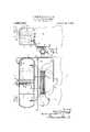
- Figure 1 is a side elevation, partly in vertical section, showin'gan engine equipped with the fuel economizing and. carbonlzation preventing means; and Fig. 2 is a vertical section on the line II-II of Fig. 1, the engine casing being shown in end elevation.
- 1 designates a steam or vapor generator supported above the enginee2 in any suitable manner.
- the vapor generator is provided with a series of transversely extending perforated partitions or plates* ⁇ 3, the upper half of the vapor generator or tank 1 forming a steam or vapor drum.
- the plates 3 are provided with perforations 4, permitting water and vapor to pass through the plates, but are adapted to prevent excessive surging of the water in the generator.
- the opposite end of pipe G 1s connected with three branch pipes 9, 10 and 11 which extend upwardly into the tank l at poilus spaced longitudinally .of said tank and to points ⁇ above the bottom thereof and preferably below or substantially 1n ahusement with the minimum water line in the tank.
- drain cock 12 is connected with the pipe 1n order that the water in tank 1 and the pipe 4system may be drained therefrom lwhen desired.
- the pipe 13 is connected at one end lwith the upper portion or vapor drum of tank 1 and is connected at its other end with the intake manifold 14 of the engine 2. It will thus be seen that a quantity of aqueous .vapor will be mingled with the gaseous fuel drawn into the engine cylinders through the intake manifold 14.
- the quantity of vapor drawn through pipe 13 may be regulated by means of a suitable valve 15 interposed in said pipe and operable from the dashboard of a motor vehicle or other point by means of an operating rod 16.
- the supply of water in tank 1 may be replenished through al filling tube 17, preferably having a suitable screen 18 therein and formed with a Haring or funnel-shaped upper end.
- the lower end of the tube 17 extends below the normal water line (indicated by dotted lines) t0 the minimum water line oftank 1.
- the filling tube 17 also serves to admit air into the generator, saidair being heated as it passes downwardly through the tube 17 and rises through the heated water in the generator.
- a suitable water gage is provided to indicate the water level in tank 1.
- This water gage may be of any suitable construction.
- tube or cylinder 19 extending to or below the minimum water line and having an open lower end preferably extending to the same llevel as the lower end of tube 17.
- a piston or oat 2O is mounted in the tube 19 and a stem or in dicator rod 21 is held at its lower end to said piston.
- the lower end of tube -19 is provided ywith an annular internal stop flange 23 for the piston or ioat 20.
- a suitable baille plate 24C is preferably held to one end wall 4of tank 1 and extends inwardly past the inlet end of pipe 13 to'prevent water from splashing or running into pipe 13.
- water clrculating andV heating pipe having its off-take end communicating with the bottom of said tank and its outlet end communicating with said tank above the bottom thereof and below the water line, said pipe being bent back and forth intermediate its vends to form an annular series of horizontally extending loops about the exhaust pipe, a drain cock connected with the lowermost bend of said pipe'whereby said tank and circulating pipe may be dralned of water, and a vapor conduit connecting the vapor space of said I tank with the intake manifold.
- a water circulating and heating pipe having its off-take end communicatlng with the bottom of said ⁇ tank and its outlet end communicating with said tank above the .bottom thereof and below the water line,
- said pipe being bent back and forth intermediate its ends to form an annular series of horizontally extending loops' about the exhaust pipe, a drain cock connected with the lowermost bend of said pipe
- said tank and circulating pipe may be drained of water
- a vapor conduit connecting the vapor space of lsaid tank with the intake manifold
- a bafile plate held to the inner side of vsaid tank above the water line and interposed between the off-take end of said vapor conduit and the body of water in the tank.
Landscapes
- Engineering & Computer Science (AREA)
- Chemical & Material Sciences (AREA)
- Combustion & Propulsion (AREA)
- Mechanical Engineering (AREA)
- General Engineering & Computer Science (AREA)
- Cooling, Air Intake And Gas Exhaust, And Fuel Tank Arrangements In Propulsion Units (AREA)
Description
E. HASBROUCK & C. E. WHITE.
FUEL SAVER AND DECAHBONIZER.
APPLICATION FILED DEC'J, 1917.
Patented Oct. 8, 19ML #5w/v w UNITED sTATEs PATENT o ri'iIoE.
EARL HASBROUCK AND CHARLES E. WHITE, OIF WALLKILL, NEW YOK.
FUEL-SAVER AND DECARBONIZEB..
Speeication of Letters Patent.
Patented Oct. 8, 1918.
Application led December 7, 1917. Serial No. 205,984.
and CHaRLEs E. WHITE, citizens of the A United States, and residents of Wallkill,
county of Ulster, and State of New York,l
have invented certain new and useful Improvements in- Fuel-Savers and Decal-bonizers, of which the following is a' specifi-- cation. 4
This invention relates to improvements in internal combustion engines and has for its object the provision of means for econoinzing fuel and for preventing the deposition of carbon in the cylinders 1n the operation of engines of this type.
In the drawings, Figure 1 is a side elevation, partly in vertical section, showin'gan engine equipped with the fuel economizing and. carbonlzation preventing means; and Fig. 2 is a vertical section on the line II-II of Fig. 1, the engine casing being shown in end elevation.
Referring to the drawings by numerals, 1 designates a steam or vapor generator supported above the enginee2 in any suitable manner. v- The vapor generator is provided with a series of transversely extending perforated partitions or plates*` 3, the upper half of the vapor generator or tank 1 forming a steam or vapor drum. The plates 3 are provided with perforations 4, permitting water and vapor to pass through the plates, but are adapted to prevent excessive surging of the water in the generator.
The water in the generator tank 1 1s adapted to be heated from the exhaust pipe 5 of the engine 2 by means of a circulating systcm comprising a pipe 6 connected at one end with the bottom of the tank 1, refer ably substantially centrally thereo and bent to form an annular series of loops 7 .extending about the exhaust p ipe 5 and h eld lhereagainst by means of suitable clamping bands 8. The opposite end of pipe G 1s connected with three branch pipes 9, 10 and 11 which extend upwardly into the tank l at poilus spaced longitudinally .of said tank and to points `above the bottom thereof and preferably below or substantially 1n ahnement with the minimum water line in the tank.-
drain cock 12 is connected with the pipe 1n order that the water in tank 1 and the pipe 4system may be drained therefrom lwhen desired.
The aqueous vapor generated when the engine is running -will accumulate in the upper portion or vapor drum of tank 1 and will be drawn off from said drum through a pipe 13 by the suction of the engine 2, The pipe 13 is connected at one end lwith the upper portion or vapor drum of tank 1 and is connected at its other end with the intake manifold 14 of the engine 2. It will thus be seen that a quantity of aqueous .vapor will be mingled with the gaseous fuel drawn into the engine cylinders through the intake manifold 14. The quantity of vapor drawn through pipe 13 may be regulated by means of a suitable valve 15 interposed in said pipe and operable from the dashboard of a motor vehicle or other point by means of an operating rod 16.
The supply of water in tank 1 may be replenished through al filling tube 17, preferably having a suitable screen 18 therein and formed with a Haring or funnel-shaped upper end. The lower end of the tube 17 extends below the normal water line (indicated by dotted lines) t0 the minimum water line oftank 1.
The filling tube 17 also serves to admit air into the generator, saidair being heated as it passes downwardly through the tube 17 and rises through the heated water in the generator.
A suitable water gage is provided to indicate the water level in tank 1. This water gage may be of any suitable construction.
s shown, it comprises a tube or cylinder 19 extending to or below the minimum water line and having an open lower end preferably extending to the same llevel as the lower end of tube 17. A piston or oat 2O is mounted in the tube 19 and a stem or in dicator rod 21 is held at its lower end to said piston. The rod'21extends upwardly through tube 19 and passes through a suitable aperture in an indicator plate 22 held to the top of tank 1. The lower end of tube -19 is provided ywith an annular internal stop flange 23 for the piston or ioat 20. A suitable baille plate 24C is preferably held to one end wall 4of tank 1 and extends inwardly past the inlet end of pipe 13 to'prevent water from splashing or running into pipe 13.
What we claim is:
1. The combination with an internal combustion. engine having an intake manifold and an exhaust pipe, of a water tank supported at a higher level than the exhaust 'pipe and having a vapor collecting space therein above the water level,a water c1rculating and heating pipe having its ofitake Y lecting space in the upper portion thereof, a
water clrculating andV heating pipe having its off-take end communicating with the bottom of said tank and its outlet end communicating with said tank above the bottom thereof and below the water line, said pipe being bent back and forth intermediate its vends to form an annular series of horizontally extending loops about the exhaust pipe, a drain cock connected with the lowermost bend of said pipe'whereby said tank and circulating pipe may be dralned of water, and a vapor conduit connecting the vapor space of said I tank with the intake manifold.
l 3. The combination with an internal co bustlon engine having an intake manifold and a -horizontally 'extending exhaust pipe,
of a water tank .supported above the level of said exhaust pipe and having a vapor collecting space in the upper portion thereof, a water circulating and heating pipe having its off-take end communicatlng with the bottom of said `tank and its outlet end communicating with said tank above the .bottom thereof and below the water line,
said pipe being bent back and forth intermediate its ends to form an annular series of horizontally extending loops' about the exhaust pipe, a drain cock connected with the lowermost bend of said pipe Whereby said tank and circulating pipe may be drained of water, a vapor conduit connecting the vapor space of lsaid tank with the intake manifold, and a bafile plate held to the inner side of vsaid tank above the water line and interposed between the off-take end of said vapor conduit and the body of water in the tank.
4. The combination with an internal combustion engine having an intake manifold and an exhaust pipe, of a'water tank supported at higher level than the exhaust pipe and having a vapor collecting space therein above the Water leved, a water circulating and heating pipe having its off-take end communicating with the bottom of said tank and its-outlet end communicating with said tank above the bottom thereof, said pipe being coiled intermediate its ends about the exhaust pipe at a point below the level of the bottom of the tank, a plurality of spaced perforated partitions extending transversely of said tank from top to bottom thereof, a vapor conduit connecting one end of the tank above the water line with the intake manifold, and a baiiie plate held to the inner side of the tank and interposed between the off-take end of Asaid vapor conduit and the body of water in the tank.
. 5. The combination with an internal combustion engine having an intake manifold and an exhaust pipe,l of a water tank supported at a higher level than the exhaust pipe and having a vapor collecting space/ therein above the water level, a water circlilating and heating pipe having itso'H-take end communicating with the bott-6m of said tank and its outlet end communicating with said Vtank above the bottorn'thereof, said pipe being coiled intermediate its ends about the i exhaust pipe at a point below the level of the bottom of the tank, a plurality of spaced perforated' partitions extending transversely of said tank from top to bottom thereof, a vapor conduit connecting one end of the tank above the water line with the intake mani-- fold, a baffle plate held to the inner 'side of the tank and interposed between the off-take end of said vapor conduit and the body of Water in the tank, and a Water and air supply tube extending vertically through the.
top of said tank and open at both ends, the lower end of said tube depending into said tank to a point below the water line.
6. The combination With an internal combustion engine having an intake manifold and an exhaust pipe, of a water tank supported at a higher level than the exhaust pipe and having a vapor collecting space therein above the water level, a water circu lating and heating pipe having its off-take end communicating with the bottom of said llO tank and its outlet end communicating with said tank above the bottom thereof, said pipe bemg colled intermediate its ends about the exhaust pipe at aA point below the level'of the bottom of the tank, a Vplurality of spaced perforated partitionsextending transversely of sald tank from top to bottom thereof, a vapor conduit connecting one end of the tank above the Water line With the intake manifold, a balile plate held to the inner side ef the tank and interposed between the olftake end of said vapor conduit and the body of water in the tank, a water and air supply v tube extending vertically through the top of said tank and open at both ends, the lower end of said tube depending into said tank to a point below the Water line, and a valve in said' vapor conduit for controlling the 10 passage of vapor therethrough to the intake manifold.
In testimony whereof We hereunto affix our signatures this 30 day of November, 1917.
EARL HASBROUCK. CHARLES E. WHITE.
Priority Applications (1)
| Application Number | Priority Date | Filing Date | Title |
|---|---|---|---|
| US20598417A US1280997A (en) | 1917-12-07 | 1917-12-07 | Fuel-saver and decarbonizer. |
Applications Claiming Priority (1)
| Application Number | Priority Date | Filing Date | Title |
|---|---|---|---|
| US20598417A US1280997A (en) | 1917-12-07 | 1917-12-07 | Fuel-saver and decarbonizer. |
Publications (1)
| Publication Number | Publication Date |
|---|---|
| US1280997A true US1280997A (en) | 1918-10-08 |
Family
ID=3348590
Family Applications (1)
| Application Number | Title | Priority Date | Filing Date |
|---|---|---|---|
| US20598417A Expired - Lifetime US1280997A (en) | 1917-12-07 | 1917-12-07 | Fuel-saver and decarbonizer. |
Country Status (1)
| Country | Link |
|---|---|
| US (1) | US1280997A (en) |
-
1917
- 1917-12-07 US US20598417A patent/US1280997A/en not_active Expired - Lifetime
Similar Documents
| Publication | Publication Date | Title |
|---|---|---|
| US1280997A (en) | Fuel-saver and decarbonizer. | |
| US1256186A (en) | Fuel-vaporizer for internal-combustion engines. | |
| US1683747A (en) | Exhaust-gas water heater | |
| US1332407A (en) | Humidifier | |
| US1250912A (en) | Cooling-mixture-conserving means for gas-engines. | |
| US499567A (en) | Augustin normand | |
| US368642A (en) | baibd | |
| US506292A (en) | And george | |
| US1627814A (en) | Radiator reflow device | |
| US287452A (en) | mcallistee | |
| US268176A (en) | blanchard | |
| US640475A (en) | Feed-water heater. | |
| US1028115A (en) | Water-cooling system for hydrocarbon-engines. | |
| US1275465A (en) | Vaporizer. | |
| US1542999A (en) | Humidifier for internal-combustion engines | |
| US1499786A (en) | Fuel economizer and carbon reducer | |
| US1260902A (en) | Fuel-supply for motors. | |
| US616431A (en) | Boiler feed water heating apparatus | |
| US1220307A (en) | Moistener for internal-combustion engines. | |
| US614743A (en) | nesbit | |
| US406265A (en) | Water heater and condenser | |
| US1555664A (en) | Apparatus for removing liquid dilutents from lubricants | |
| US1077414A (en) | Cooling device for an engine. | |
| US1572278A (en) | Steam injector for internal-combustion engines | |
| US354368A (en) | Feed-water heater |