US1257504A - Scythe-blade fastener. - Google Patents
Scythe-blade fastener. Download PDFInfo
- Publication number
- US1257504A US1257504A US18730517A US18730517A US1257504A US 1257504 A US1257504 A US 1257504A US 18730517 A US18730517 A US 18730517A US 18730517 A US18730517 A US 18730517A US 1257504 A US1257504 A US 1257504A
- Authority
- US
- United States
- Prior art keywords
- ferrule
- handle
- scythe
- blade
- shank
- Prior art date
- Legal status (The legal status is an assumption and is not a legal conclusion. Google has not performed a legal analysis and makes no representation as to the accuracy of the status listed.)
- Expired - Lifetime
Links
- 238000010276 construction Methods 0.000 description 3
- 238000000034 method Methods 0.000 description 1
Images
Classifications
-
- A—HUMAN NECESSITIES
- A61—MEDICAL OR VETERINARY SCIENCE; HYGIENE
- A61M—DEVICES FOR INTRODUCING MEDIA INTO, OR ONTO, THE BODY; DEVICES FOR TRANSDUCING BODY MEDIA OR FOR TAKING MEDIA FROM THE BODY; DEVICES FOR PRODUCING OR ENDING SLEEP OR STUPOR
- A61M5/00—Devices for bringing media into the body in a subcutaneous, intra-vascular or intramuscular way; Accessories therefor, e.g. filling or cleaning devices, arm-rests
- A61M5/14—Infusion devices, e.g. infusing by gravity; Blood infusion; Accessories therefor
- A61M5/1413—Modular systems comprising interconnecting elements
Definitions
- scythe blade in connection with its snathe or "handle, and which is so constructed as to permit the blade to be readily removed when found desirable to do so.
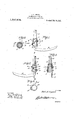
- Figure 1 represents a side elevation of the blade and of a scythe, the handle being broken off for convenience inill'ustration and with parts broken out,
- Fig. 2 isa similar view taken from the opposite side of the scythe,'
- Fig. 3 is a horizontal section taken 011 the line 33 of Fig. 1,
- Fig. 4 is a longitudinal section taken on the lined- 1 of Fig.2, and
- Fi 5 is a plan view of one of the rings showing the wrench for use in connection therewith in operative position with parts broken out.
- a scythe handle or snathe H is shown having one side thereof flattened as shown at h and which carries a blade B of ordinary construction having the usual shank S and which is designed to be secured to the handle H by a fastener presently to be described which constitutes this invention.
- the shank S has an inturned finger s at its free end which is designed to enter an aperture in the handle H through an open- Patented ll eb as, rare.
- the fastener constituting this invention comprises a tapered ferrule 1 shaped to engage the lower end of the handlejfll having a fiat inner side wall2 which 'isdesigned to fit over the flat face it of said handle and thereby prevent all possibility of the ferrule turning on the handle and which is further secured to the handle by means of a bolt 3 which extends transversely through an apertured lugjt carried by the upper end of the ferrule and transversely through the handle as is shown clearly in Figs. 1, 2, and 42.
- This ferrule 1 is externally threaded as shown clearly at 5 in Figs. 1,2 and l and is split longitudinally throughout its length as shown at 6 to permit it to closely engage the handle whenv the clamping rings 10 and 11 are placed in operative position.
- This ferrule 1 has a recess 7 arranged longitudinally in its'outer' face on the flattened portion thereof as isshown clearly in Fig. 3 and which forms a seat for the shank S of the scythe blade when the parts are assembled as is shown clearly in Fig. 3.
- the ferrule retaining and clamping rings orb-ands 10 and 11 are internally threaded to fit the threads of the ferrule 1 and similar threads 8 which are carried by the outer face of shank S, said threads 8 being so formed as to register with the threads 5 of the ferrule when the parts are assembled and form a continuation of said threads.
- These rings are also provided each-with a radially eX-, tending stud 9 which is designed to be engaged by a wrench '12 having an aperture 13 in one end adapted to fit over said stud to facilitate the screwing and unscrewing of the rings.
- This wrench has a handle 14 projecting longitudinally therefrom to afford ample leverage for operating the rings, said handle being shown broken off in Fig. 5 for convenience in illustration.
- the ferrule 1 is first placed on the lower end of handle H and secured thereto by the bolt 3,
- the shank S then has its inturned finger or spur s at its free end engaged with the aperture 0 in the ferrule and the corresponding opening in the handle H as is shown clearly in Fig. 4.
- the rings 10 and 11 are. then screwed down over the ferrule and shank S thereby forcing said ferrule into tight clamping engagement with the shank and the handle so that the shank is securely held against all possibility of its this connection.
- a ferrule mounted on said handle, cooperating means carried by said handle and fer rule for holding the ferrule against turning on the handle, a seat extending longitudinally of said ferrule, threads formed on the exterior of the ferrule, a blade having a turning, the two rings operating to insure shank adapted to fit in said seat and PTO: vided with threads on its outer face adapted to register with the threads on the ferrule, and a clamping band having interior threads for engaging the threads of the ferrule and shank whereby they are locked to each other and to the handle.
- a'scythe handle having one face flattened at its lower end, a tapered ferrule having a fiat inner face to fit on said handle and whereby it'is held against turning relatively thereto, a seat extending longitudinally of said ferrule on its outer face, said ferrule being split from end to end with the edges of said split portion normally spaced apart, a blade having a shank adapted to fit in said seat, and a clamping band for engaging said ferrule and shank for locking them together.
- a scythe blade fastener comprisin a longitudinally split exteriorly threaded ferrule having a seat extending longitudinally of its outer face to receive the shank of a blade, clamping bands interiorly threaded to fit the threads of said ferrule, and means carried by said bands to facilitate the turning of the bands on the ferrule.
- a scythe blade fastener comprisin a longitudinally split exteriorly threaded ferrule having a seat extending longitudinally of its outer face to receive the shank of a blade, clamping bands interiorly threaded to fit the threads of said ferrule, and studs extending radially from said bands to facilitate the turning of the bands on the ferrule.
Landscapes
- Health & Medical Sciences (AREA)
- Vascular Medicine (AREA)
- Engineering & Computer Science (AREA)
- Anesthesiology (AREA)
- Biomedical Technology (AREA)
- Heart & Thoracic Surgery (AREA)
- Hematology (AREA)
- Life Sciences & Earth Sciences (AREA)
- Animal Behavior & Ethology (AREA)
- General Health & Medical Sciences (AREA)
- Public Health (AREA)
- Veterinary Medicine (AREA)
- Knives (AREA)
Description
E. E. LIPPERT. SCYTHE BLADE FASTENER. APPLICATION FILED AUG-20, 19-11.
1921mm Ml Feb. 26, 1918.
1 m w a INVENTOR Z227? Zip 0W2 WITNESSES ATTORTEY fication.
nirn s'ranrs ranrrr rat on.
EARL E. LIPPERT, OF STROUI), DlKLAHOMA.
- serene-scans rasrnnnn.
earner.
Specification of Letters Eatent.
Application an August so, we. Eeria11to.187,305.
' a simply constructed and efficient device of this character in which the :parts, while simple, will reliably and firmly hold the,
scythe blade in connection with its snathe or "handle, and which is so constructed as to permit the blade to be readily removed when found desirable to do so.
With the foregoing and other objects in View, which will appear as the description roceeds, the invention resides in the com ination and arrangement of parts and in the details of construction hereinafter described and claimed, it being understood that changes in the precise embodiment of the invention herein disclosed may be made within the scope of what is claimed without departing from the spirit of the invention.
In the accompanying drawings:-
. Figure 1 represents a side elevation of the blade and of a scythe, the handle being broken off for convenience inill'ustration and with parts broken out,
Fig. 2 isa similar view taken from the opposite side of the scythe,'
Fig. 3 is a horizontal section taken 011 the line 33 of Fig. 1,
Fig. 4 is a longitudinal section taken on the lined- 1 of Fig.2, and
Fi 5 is a plan view of one of the rings showing the wrench for use in connection therewith in operative position with parts broken out.
In the embodiment illustrated a scythe handle or snathe H is shown having one side thereof flattened as shown at h and which carries a blade B of ordinary construction having the usual shank S and which is designed to be secured to the handle H by a fastener presently to be described which constitutes this invention. a
The shank S has an inturned finger s at its free end which is designed to enter an aperture in the handle H through an open- Patented ll eb as, rare.
ing 0 formed in the ferrule presently to be described.
The fastener constituting this invention comprises a tapered ferrule 1 shaped to engage the lower end of the handlejfll having a fiat inner side wall2 which 'isdesigned to fit over the flat face it of said handle and thereby prevent all possibility of the ferrule turning on the handle and which is further secured to the handle by means of a bolt 3 which extends transversely through an apertured lugjt carried by the upper end of the ferrule and transversely through the handle as is shown clearly in Figs. 1, 2, and 42. This ferrule 1 is externally threaded as shown clearly at 5 in Figs. 1,2 and l and is split longitudinally throughout its length as shown at 6 to permit it to closely engage the handle whenv the clamping rings 10 and 11 are placed in operative position. as will-be presently described. This ferrule 1 has a recess 7 arranged longitudinally in its'outer' face on the flattened portion thereof as isshown clearly in Fig. 3 and which forms a seat for the shank S of the scythe blade when the parts are assembled as is shown clearly in Fig. 3.
The ferrule retaining and clamping rings orb-ands 10 and 11 are internally threaded to fit the threads of the ferrule 1 and similar threads 8 which are carried by the outer face of shank S, said threads 8 being so formed as to register with the threads 5 of the ferrule when the parts are assembled and form a continuation of said threads. These rings are also provided each-with a radially eX-, tending stud 9 which is designed to be engaged by a wrench '12 having an aperture 13 in one end adapted to fit over said stud to facilitate the screwing and unscrewing of the rings. This wrench has a handle 14 projecting longitudinally therefrom to afford ample leverage for operating the rings, said handle being shown broken off in Fig. 5 for convenience in illustration.
From the above description it will be obvious that in the assembling of the parts of this device, the ferrule 1 is first placed on the lower end of handle H and secured thereto by the bolt 3, The shank S then has its inturned finger or spur s at its free end engaged with the aperture 0 in the ferrule and the corresponding opening in the handle H as is shown clearly in Fig. 4. The rings 10 and 11 are. then screwed down over the ferrule and shank S thereby forcing said ferrule into tight clamping engagement with the shank and the handle so that the shank is securely held against all possibility of its this connection.
When it is desired to remove the blade for any reason the ringsare first removed by enconnection with the accompanying drawings,
the advantages of the construction and of the method of operation will'be readily apparent to those skilled in the art to which the invention appertains and while I have described the principleof operation of the invention together with the device which I now consider to be the best embodiment thereof, I desire to have it understood that the device shown is merely illustrative and that such changes may be made as are within the scope of the claimed invention.
I claim:
1. The combination with a scythe handle,
a ferrule mounted on said handle, cooperating means carried by said handle and fer rule for holding the ferrule against turning on the handle, a seat extending longitudinally of said ferrule, threads formed on the exterior of the ferrule, a blade having a turning, the two rings operating to insure shank adapted to fit in said seat and PTO: vided with threads on its outer face adapted to register with the threads on the ferrule, and a clamping band having interior threads for engaging the threads of the ferrule and shank whereby they are locked to each other and to the handle.
2. The combinationwith a'scythe handle having one face flattened at its lower end, a tapered ferrule having a fiat inner face to fit on said handle and whereby it'is held against turning relatively thereto, a seat extending longitudinally of said ferrule on its outer face, said ferrule being split from end to end with the edges of said split portion normally spaced apart, a blade having a shank adapted to fit in said seat, and a clamping band for engaging said ferrule and shank for locking them together.
3. A scythe blade fastener comprisin a longitudinally split exteriorly threaded ferrule having a seat extending longitudinally of its outer face to receive the shank of a blade, clamping bands interiorly threaded to fit the threads of said ferrule, and means carried by said bands to facilitate the turning of the bands on the ferrule.
4. A scythe blade fastener comprisin a longitudinally split exteriorly threaded ferrule having a seat extending longitudinally of its outer face to receive the shank of a blade, clamping bands interiorly threaded to fit the threads of said ferrule, and studs extending radially from said bands to facilitate the turning of the bands on the ferrule.
In testimony whereof I afiix my signature in presence of two witnesses.
EARL E. LIPPERT.
Witnesses D. G. Domes, H. V. Conn.
Priority Applications (1)
| Application Number | Priority Date | Filing Date | Title |
|---|---|---|---|
| US18730517A US1257504A (en) | 1917-08-20 | 1917-08-20 | Scythe-blade fastener. |
Applications Claiming Priority (1)
| Application Number | Priority Date | Filing Date | Title |
|---|---|---|---|
| US18730517A US1257504A (en) | 1917-08-20 | 1917-08-20 | Scythe-blade fastener. |
Publications (1)
| Publication Number | Publication Date |
|---|---|
| US1257504A true US1257504A (en) | 1918-02-26 |
Family
ID=3325193
Family Applications (1)
| Application Number | Title | Priority Date | Filing Date |
|---|---|---|---|
| US18730517A Expired - Lifetime US1257504A (en) | 1917-08-20 | 1917-08-20 | Scythe-blade fastener. |
Country Status (1)
| Country | Link |
|---|---|
| US (1) | US1257504A (en) |
-
1917
- 1917-08-20 US US18730517A patent/US1257504A/en not_active Expired - Lifetime
Similar Documents
| Publication | Publication Date | Title |
|---|---|---|
| US1371742A (en) | Nut-lock | |
| US1300275A (en) | Screw-threaded fastening. | |
| US930450A (en) | Bolt and nut lock. | |
| US1020668A (en) | Nut-lock. | |
| US2306228A (en) | Ratchet wrench | |
| US1257504A (en) | Scythe-blade fastener. | |
| US1414979A (en) | Convertible bolt | |
| US1944595A (en) | Lock nut | |
| US1287270A (en) | Automatic locking device. | |
| US1734743A (en) | Nut lock | |
| US856868A (en) | Ratchet-bolt. | |
| US1298469A (en) | Nut-lock. | |
| US1207356A (en) | Lock-nut. | |
| US2278344A (en) | Lock bolt construction | |
| US1368723A (en) | Valve-cap | |
| US1339015A (en) | Nut-lock | |
| US1137042A (en) | Nut-lock. | |
| US1166220A (en) | Bolt-lock. | |
| US783088A (en) | Lock-nut. | |
| US1763505A (en) | Self-tightening nut | |
| US878197A (en) | Wrench. | |
| US827941A (en) | Nut-lock. | |
| US1049249A (en) | Pick. | |
| US1238962A (en) | Lock-washer. | |
| US1202096A (en) | Nut-lock. |