US1241663A - Self-grinding rotary valve. - Google Patents
Self-grinding rotary valve. Download PDFInfo
- Publication number
- US1241663A US1241663A US15013517A US15013517A US1241663A US 1241663 A US1241663 A US 1241663A US 15013517 A US15013517 A US 15013517A US 15013517 A US15013517 A US 15013517A US 1241663 A US1241663 A US 1241663A
- Authority
- US
- United States
- Prior art keywords
- valve
- tapered
- ports
- cylinders
- sleeve
- Prior art date
- Legal status (The legal status is an assumption and is not a legal conclusion. Google has not performed a legal analysis and makes no representation as to the accuracy of the status listed.)
- Expired - Lifetime
Links
- 230000006698 induction Effects 0.000 description 20
- 239000002360 explosive Substances 0.000 description 10
- 239000000314 lubricant Substances 0.000 description 6
- 230000007246 mechanism Effects 0.000 description 4
- 238000002485 combustion reaction Methods 0.000 description 3
- 238000010276 construction Methods 0.000 description 3
- 230000006872 improvement Effects 0.000 description 3
- 239000000203 mixture Substances 0.000 description 3
- 230000009471 action Effects 0.000 description 2
- 230000015572 biosynthetic process Effects 0.000 description 2
- 239000003795 chemical substances by application Substances 0.000 description 2
- 230000006835 compression Effects 0.000 description 2
- 238000007906 compression Methods 0.000 description 2
- 230000013707 sensory perception of sound Effects 0.000 description 2
- 102100026933 Myelin-associated neurite-outgrowth inhibitor Human genes 0.000 description 1
- 230000008859 change Effects 0.000 description 1
- 238000006073 displacement reaction Methods 0.000 description 1
- 230000000694 effects Effects 0.000 description 1
- 238000004880 explosion Methods 0.000 description 1
- 238000010304 firing Methods 0.000 description 1
- 235000013531 gin Nutrition 0.000 description 1
- 230000002035 prolonged effect Effects 0.000 description 1
Images
Classifications
-
- F—MECHANICAL ENGINEERING; LIGHTING; HEATING; WEAPONS; BLASTING
- F01—MACHINES OR ENGINES IN GENERAL; ENGINE PLANTS IN GENERAL; STEAM ENGINES
- F01L—CYCLICALLY OPERATING VALVES FOR MACHINES OR ENGINES
- F01L7/00—Rotary or oscillatory slide valve-gear or valve arrangements
- F01L7/08—Rotary or oscillatory slide valve-gear or valve arrangements with conically or frusto-conically shaped valves
Definitions
- This invention which has reference to improvements in internal combustion en- 'gines, more particularly seeks to provide an improved rotary valve construction, practically noiseless in operation, that can be economically manufactured, in which the operating parts are especially designed for increasing the elliciency or power of motors and in such manner whereby to economize in the use of the Working agent.
- my present invention has for its purpose to provide certain improvements on 'the self grinding valve con-V struction disclosed in my copending application, Serial No. 131,921, allowed J anuary 8, 1917.
- My invention primarily has forits purpose, to provide an improved self grinding and adjustable valve mechanism that has all of the advantages of the tapered valve features and in which special provision is includedso that all of the ports may be of equal size' or depth to secure uniformity in compression and the passage of the exploded inixture and effect the saine displacementand clearance in all of the cylinders.
- present invention embodies in a rotary valve. Ille peculiar fenY tures of construction and cooperative nrA rangement of the )arts to he lirsl explained in detail,specically set out in the appended claims and illustrated in the acconipairnne drawings, in which:
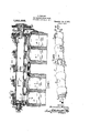
- Figure l is a longitudinal .section of niv improved rotary valve, so nnn'h ot' u cvlxi der head with t'our cylinders being sliown to illustrate the practical application ot' my invention.
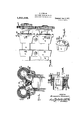
- Fi 2 is a transverse section thereof on the line 2-2 on Fig. 1.
- Fig. 3 is a perspective view of the valve proper.
- Fig. 5 is a top plan view of the frontend of a pair of valve mechanisms, with the driving gear devices attached.
- FIG. 4 is a perspective vieu' of one' of the 'i Fig. 6 is a detail section showing the mani'- "i: l"
- I have sliovvn a portion A of a motor engine that 'includes four cylinders. designated A. B, C and D, it being i understood that While I have shovvn fou-i' cylinders, my improved valve mechanism is applicable for use v vith engines having a /greater or lesser number of cylinders.
- the valve S is a holloubody.
- the bore of which is cylindrical throughout its length and at predetermined points, corresponding to the number of cylinders, the said valve is annularly thickened to form cone-lilte bearings l, tlie smaller ends of, which are of substantially the, diameter of the cylindrical valve body (may be more), ⁇ the larger end being of any diameter desired that will not f readily stick, and at this point,f it sliould'be stated, the larger ends of the vconical or tapered portions 1 are of about or a little smaller diameter than that of the smaller ends of the external housings 3, such relative proportions of the parts being provided,
- each housing 3 of which there is one for each cone shaped or tapering bearing 1-1, are cast en bloc with the cylinder head, as is best shown in Fig. '2, by reference to which and to Fig. 1 it will be noticed a tapering sleeve 2 is located between each housing 3 and cone bearing 1, to overcome the Wearing of the parts and to make it easy for installing new bearing surfaces for the cone portions 1 of the valve, when conditions make it necessary to do so.
- each sleeve 2 is made of two half sections -31, one of which, at the larger end has retaining lugs 32 that engage corresponding recesses 32aL in the opposing section, and the upper member 30 has a socket 3l for receiving the lower end of a retaining screw 4 that passes through a threaded aperture in the hoiising 3, which holds the sleeve sections from endwise slipping out of proper position.
- the valve S which as before stated, is a Acylindrical cone 1, has one end that terminates in a cone shaped bearing 19 which is prolonged to form a sleeve 20, that has a square shaped end 21 for fitting in a correspfoiidiuglyV shaped socket of a shaft 2:2 that ca' ries the driving gear 2'2, to which power transmitted by suitable means, for ex- Hftrrpl'e' like the means disclosed in my copending application.
- the valve body Centrally between the cylinders B and C, the valve body has an additional cone or taper bearing 1 which coperates with a housing 3, a sleeve 2 and the intake or exhaust manifolds, as will presently more fully appear.
- That end of the valve over the cylinder D has a portion 7 o reduced diameter to form an annular space or seat 16 for receiving the roller bearings 17, and the said reduced portion 7 terminates in a stem 8 having a threaded end, as shown.
- the external tapering housing 3 at the reduced end of the valve cast with the cylinderor motor head, is formed with a cylindrical portion that extends a little beyond the adjacent end of the valve to provide a space 15 between the ends of the valve and a disk 9 attached by screws 11 to the outer edge of the cylindrical extension of the said housing member, the said space 15 being provided to give room for the valve to automatically move rearwardly as it Wears or grinds down.
- the disk 9 ljust referred to, has an integral hollow cylinder extension 10 that constitutes a housing for a coiled spring 12 held at one end against a disk 50 on the stem 8 that bears against the disk 9 and provided with ball bearings 51 on its inner face that rotates on the said disk 9.
- the other end of the spring 12 bears against a disk 13 on the stem 8 and is held up in proper place by nuts 14 that engage the out-er threaded end of the stem 8, as shown.
- the rotation of the valve will at all times be smooth, practically noiseless, and under a pulling action of the spring 1'2 that tends at all times to hold the cone bearings 1 of the valve up under grinding action against the conical housing 3.
- each external housing Under the bottom of each external housing the cylinder or motor head is provided with a longitudinal oil groove 21 that extends nearly the full length of the housing and the coperating lower part of each valve sleeve 2 is provided with lubricant passages 25.
- a pipe 26 In the smaller end of each sleeve is a pipe 26 through which the lubricant is introduced to the said passages 25 and th corresponding valve bearings and at the larger end another pipe 27 is connected with the passages Q5 for draining oil" the lubricant.
- the several oil feed pipes 26 connect with a common feed pipe, and the several drain pipes 2T with a common oil'- take pipe ⁇
- the valve S at points along the cone bearings that correspond to the respective cylinders A, B, C and D, is provided with a pro ortionate port P, with the several ports isposed relatively to each other in the firing order of the motor.
- Ports P are longer toward the larger end of the cone bearings, in roportion to length nf the ports P' in the s eeves 2 and the external housings 3, to compensate for the endwise automatic shifting of the valve, due to wearing. and thereby overcome any tendency of change in the displacement and clear ⁇ ance in all of the cylinders.
- the middle cone bearing is provided with a number of ports )I to constantly maintain the passage of the explosive mixture into or out of the hollow valve.
- a hollow cylindrical valve having induction and eduction ports, a tapering casing section having induction and eduction ports communicating with the valve, other tapering vcasing sections, one for each of the engine cylinders, said valve having tapering bearings for coengaging with the tapering casing sections and a single means for constantly holding the tapered valve bearings in tight engagement with their respective tapered casing sections and means for rotating the valve.
- the combination with the cylinder head having a central tapered hollow casing section prodiametrically oppositely disposed induction and eduction ports and othertapcred hollow casing sections, one for each cylinder, each of the sections having induction and eduction ports for controlling the induction and eduction of the explosive agent to and from their respective cylinders; of a hollow cylindrical rotary valve having transversely disposed ports for controlling the induction and eduction ports of the central tapered hollow casing section and having other ports for communicating with the ports in the other tapered yvalve casing section, said hollow cylindrical valve being endwise slidable into the several tapered valve casing sections and provided with tapered bearings for engaging the several tapered casing bearings, means for holding the valve in tight engagement with their respective tapered valve casmg seats, and means for rotating the valve.
- said head having an annular tapered hollow casing section located midway the cylinders and other tapered casing sections, one for each of the cylinders, a tapered sleeve for each tapered casing section, the sleeve for the middle section having engine manifold induction and eduction ports, ⁇ the other sleeve sections having induction and eduction ports; of a hollow cylindrical valve common to all of the tapered casing sections, said valve being'endwise slidable in the tapered sections and have tapered bearing portions, one for each of the tapered casing sections, thesaid hearing sections having ports arranged one. for each cylinder, and means constantly holding the tapering valve bearings in tight engagement with their respective tapered casing sections and means for rotating the valve.
- the said head having annular tapered hollow casing sections one of which is located midway the cylinders and one for each of the cylinders and a two part tapered sleeve for each tapered casing section, the sleeve for the middle section having engine manifold induction and eduction ports, the other sleeve sections having induction and eduction ports; of a hollow cylindrical valve common to all of the tapered casing sleeves, said valve being endwise slidable into the said tapered sleeves and having tapered bearing portions for each of the tapered sleeves, said bearing portions havin ports arranged for successively alining wit their respective engine cylinder ports, means for holding the valve bearings in a grinding engagement with their coengagin tapered sleeve hearings, and other means or rotating the valves, each of the tapered sleeves having a lubricant pocket that opens through the valve seat and an infeed and a drain connection for the said lubricant pocket.
- the said head having annular tapered hollow casing sections one of which is located midway the cylinders and one for each of the cylinders and a two part tapered sleeve for bustion engines, the combination with a each tapered casing section, the sleeve for plurality of explosive cylinders, each havthe middle section having engine manifold ing a port for the induction and eduction induction and eduction ports, the other of the working agent, a valve casing con- 5 sleeve sections havinvr induction and educsisting of a tapering valve seat located lnidin tion ports; of a hollow cylindrical valve vvay a pair of the cylinders, other tapering common to all of the tapered casing sleeves, valve seats, one for each of the cylinders, said valve being endivise slidable into the each of the other valve seats having ports said tapered sleeves and having tapered alining the ports
- each of the tapered sleeves being a holloiv cylindrical body of uniform having a luloricant pocket that opens diameter its length and having external tathrough the valve seat and an infeed and a pei-ing bearing sections for coengaging the 2o drain connection for the said lubricant se'veral tapering valve casings, and means pocket, the aforesaid tivo part sleeve mernfor holding the valve with its tapering secbers having interlocking portions and means tions in grinding Contact with their respecfor -xedly holding the sleeves in their retive valve casings and other means for rotatspective annular casing sections. ing the valve.
Landscapes
- Engineering & Computer Science (AREA)
- Mechanical Engineering (AREA)
- General Engineering & Computer Science (AREA)
- Valve-Gear Or Valve Arrangements (AREA)
Description
D. RONCONI. SELF GRINDING ROTARY VALVE.
APPLICATION IILED FEB, 2|. 19H. 1,241,663. Patented oen 2,1917.
2 SHEETS--SIIEET I. e 'Si ne WMI@ h 9) lI *u |4 l I vae @I u J l f I Hin.
D. RONCUNI.
sur GmNnlNG Ronny VALVE.
Arrucmou mso "8.21. m1.
Patented Oct. 2,1917.
2 SHEETS-SHEET 2 ff Mmmm" l //////////////////l l l HIIH INVENTOR ,Dome nico Rona-on 1;. 6MB
ATTORNEYS DOMENICO RONCONI. 0F CHICAGO, ILLINOIS,
sELF-enINDING ROTARY VALVE.
Specification of Letters Patent.
Patented Oct. 2, 1917.
Application tiled February 21, 1917. Serial No. 150,135.
T o all whom it may concern.'
Be it known that I, Donisxico Roxcoxi, a subject of the King of Italy, at present residing in the city of Chicago, in the county of Cool: and State of Illinois, have invented a new and Improved Self-Grinding Rotary Valve, of which the following is a specification.
This invention, which has reference to improvements in internal combustion en- 'gines, more particularly seeks to provide an improved rotary valve construction, practically noiseless in operation, that can be economically manufactured, in which the operating parts are especially designed for increasing the elliciency or power of motors and in such manner whereby to economize in the use of the Working agent.
More specifically my present invention has for its purpose to provide certain improvements on 'the self grinding valve con-V struction disclosed in my copending application, Serial No. 131,921, allowed J anuary 8, 1917.
In the practical application of rotary valves of the tapered or cone shaped type, by reason of diierent diameters of the valve at points in line with the progressively arranged cylinders, some special formation of the successively operating intake and exhaust in the valve for their respective cylinders, or some special formation of the cylinders and their pistons must be provided to secure uniformity iii compression and passage of the explosive mixture.
In using tapered rotary valves,.a small tapered valve tends to stick on the surface of the valve incasing sleeve or chamber, and in the use of large tapered valve, the difierence in diameters at the larger and the smaller4 ends is so great, that diierent lergths of cylinders or connecting rods ot di erent lengths are necessary to provide for the desired timing of the explosive mixtures in the several successively operating cylinders.
My invention primarily has forits purpose, to provide an improved self grinding and adjustable valve mechanism that has all of the advantages of the tapered valve features and in which special provision is includedso that all of the ports may be of equal size' or depth to secure uniformity in compression and the passage of the exploded inixture and effect the saine displacementand clearance in all of the cylinders. l
vWith other objects in vieu that will be hereinafter explained. 1n present invention embodies in a rotary valve. Ille peculiar fenY tures of construction and cooperative nrA rangement of the )arts to he lirsl explained in detail,specically set out in the appended claims and illustrated in the acconipairnne drawings, in which:
Figure l is a longitudinal .section of niv improved rotary valve, so nnn'h ot' u cvlxi der head with t'our cylinders being sliown to illustrate the practical application ot' my invention.
Fig. 3 is a perspective view of the valve proper.
Fig. sleeve members hereinafter referred to. j
Fig. 5 is a top plan view of the frontend of a pair of valve mechanisms, with the driving gear devices attached.
4 is a perspective vieu' of one' of the 'i Fig. 6 is a detail section showing the mani'- "i: l"
ner in which the tapered sleeves are slid in place after the valve has been inserted. n
In the drawings, I have sliovvn a portion A of a motor engine that 'includes four cylinders. designated A. B, C and D, it being i understood that While I have shovvn fou-i' cylinders, my improved valve mechanism is applicable for use v vith engines having a /greater or lesser number of cylinders.
In my present form of valve mechanism, the valve S is a holloubody. the bore of which is cylindrical throughout its length and at predetermined points, corresponding to the number of cylinders, the said valve is annularly thickened to form cone-lilte bearings l, tlie smaller ends of, which are of substantially the, diameter of the cylindrical valve body (may be more), `the larger end being of any diameter desired that will not f readily stick, and at this point,f it sliould'be stated, the larger ends of the vconical or tapered portions 1 are of about or a little smaller diameter than that of the smaller ends of the external housings 3, such relative proportions of the parts being provided,
to facilitate the shoving of the valve bodyi into the operative position, within 'the' yseveral housings 3, as will hereinafter', more fully appear.
The several housings 3, of which there is one for each cone shaped or tapering bearing 1-1, are cast en bloc with the cylinder head, as is best shown in Fig. '2, by reference to which and to Fig. 1 it will be noticed a tapering sleeve 2 is located between each housing 3 and cone bearing 1, to overcome the Wearing of the parts and to make it easy for installing new bearing surfaces for the cone portions 1 of the valve, when conditions make it necessary to do so.
It should be mentioned that the distance space'between the adjacent ends of the cones, as indicated by 5--5 on Fig. 1, is a little more than the length of the space 6-6 of the cones, such spacing of the parts, the purpose of which isto provide for placing the sleeves 2 in positron when putting the valve in operative positionit being understood from the drawings, each sleeve 2 is made of two half sections -31, one of which, at the larger end has retaining lugs 32 that engage corresponding recesses 32aL in the opposing section, and the upper member 30 has a socket 3l for receiving the lower end of a retaining screw 4 that passes through a threaded aperture in the hoiising 3, which holds the sleeve sections from endwise slipping out of proper position.
' The valve S, which as before stated, is a Acylindrical cone 1, has one end that terminates in a cone shaped bearing 19 which is prolonged to form a sleeve 20, that has a square shaped end 21 for fitting in a correspfoiidiuglyV shaped socket of a shaft 2:2 that ca' ries the driving gear 2'2, to which power transmitted by suitable means, for ex- Hftrrpl'e' like the means disclosed in my copending application.
The external housing 3, at the cone shaped end of the valve, extends a short distance over thev said end and terminates in a rightangled flange 1S, to which is bolted a thrust collar 35 having an internal thread 35 for receiving a ball bearing holder 40 that screws into the dollar 3 5 and which has a plurality of; ball races or -grooves that receive the bearing balls 36-37, that provide for the easy and smooth movement of the valve.
Centrally between the cylinders B and C, the valve body has an additional cone or taper bearing 1 which coperates with a housing 3, a sleeve 2 and the intake or exhaust manifolds, as will presently more fully appear.
That end of the valve over the cylinder D has a portion 7 o reduced diameter to form an annular space or seat 16 for receiving the roller bearings 17, and the said reduced portion 7 terminates in a stem 8 having a threaded end, as shown.
The external tapering housing 3, at the reduced end of the valve cast with the cylinderor motor head, is formed with a cylindrical portion that extends a little beyond the adjacent end of the valve to provide a space 15 between the ends of the valve and a disk 9 attached by screws 11 to the outer edge of the cylindrical extension of the said housing member, the said space 15 being provided to give room for the valve to automatically move rearwardly as it Wears or grinds down.
The disk 9 ljust referred to, has an integral hollow cylinder extension 10 that constitutes a housing for a coiled spring 12 held at one end against a disk 50 on the stem 8 that bears against the disk 9 and provided with ball bearings 51 on its inner face that rotates on the said disk 9. The other end of the spring 12 bears against a disk 13 on the stem 8 and is held up in proper place by nuts 14 that engage the out-er threaded end of the stem 8, as shown.
By arranging the ball bearing elements for the valve, as stated and shown, the rotation of the valve will at all times be smooth, practically noiseless, and under a pulling action of the spring 1'2 that tends at all times to hold the cone bearings 1 of the valve up under grinding action against the conical housing 3.
Under the bottom of each external housing the cylinder or motor head is provided with a longitudinal oil groove 21 that extends nearly the full length of the housing and the coperating lower part of each valve sleeve 2 is provided with lubricant passages 25. In the smaller end of each sleeve is a pipe 26 through which the lubricant is introduced to the said passages 25 and th corresponding valve bearings and at the larger end another pipe 27 is connected with the passages Q5 for draining oil" the lubricant.
In practice, the several oil feed pipes 26 connect with a common feed pipe, and the several drain pipes 2T with a common oil'- take pipe` The valve S, at points along the cone bearings that correspond to the respective cylinders A, B, C and D, is provided with a pro ortionate port P, with the several ports isposed relatively to each other in the firing order of the motor.
Ports P are longer toward the larger end of the cone bearings, in roportion to length nf the ports P' in the s eeves 2 and the external housings 3, to compensate for the endwise automatic shifting of the valve, due to wearing. and thereby overcome any tendency of change in the displacement and clear` ance in all of the cylinders.
The middle cone bearing is provided with a number of ports )I to constantly maintain the passage of the explosive mixture into or out of the hollow valve.
From the foregoing taken' in connection with the accompanying drawings. the complete construction, the manner of operation vided with and the advantages of my present invention will be readily apparent to those skilled in the art to which it appertains.
W'hat I claim is:
1. In an explosive engine having one or more explosion cylinders, each having induction and eduction ports; a tapering valve casing for each cylinder, each having an induction and an eduction port alining for communicating with their respective engine cylinders; of a hollow cylindrical valve having ports for controlling the ports in the tapering valve casin said valve including tapering portions for seating in the tapering valve casings for the engine cylinders,
means for holding the valve constantlyagainst its seats and means for rotating the valve.
2. A hollow cylindrical valve having induction and eduction ports, a tapering casing section having induction and eduction ports communicating with the valve, other tapering vcasing sections, one for each of the engine cylinders, said valve having tapering bearings for coengaging with the tapering casing sections and a single means for constantly holding the tapered valve bearings in tight engagement with their respective tapered casing sections and means for rotating the valve.
In an internal combustion engine, the combination with the cylinder head having a central tapered hollow casing section prodiametrically oppositely disposed induction and eduction ports and othertapcred hollow casing sections, one for each cylinder, each of the sections having induction and eduction ports for controlling the induction and eduction of the explosive agent to and from their respective cylinders; of a hollow cylindrical rotary valve having transversely disposed ports for controlling the induction and eduction ports of the central tapered hollow casing section and having other ports for communicating with the ports in the other tapered yvalve casing section, said hollow cylindrical valve being endwise slidable into the several tapered valve casing sections and provided with tapered bearings for engaging the several tapered casing bearings, means for holding the valve in tight engagement with their respective tapered valve casmg seats, and means for rotating the valve.
4. In combination with the cylinder head and at least two explosive cylinders, said head having an annular tapered hollow casing section located midway the cylinders and other tapered casing sections, one for each of the cylinders, a tapered sleeve for each tapered casing section, the sleeve for the middle section having engine manifold induction and eduction ports, `the other sleeve sections having induction and eduction ports; of a hollow cylindrical valve common to all of the tapered casing sections, said valve being'endwise slidable in the tapered sections and have tapered bearing portions, one for each of the tapered casing sections, thesaid hearing sections having ports arranged one. for each cylinder, and means constantly holding the tapering valve bearings in tight engagement with their respective tapered casing sections and means for rotating the valve.
5. In an internal combustion en ine, the combination with the cylinder hea having a central tapered hollow casing section, having dianietrically oppositely disposed induction and educ'tion ports and other tapered hollow casing sections, one for each cylinder and each having induction and eduction ports for controlling the induction and eduction of the explosive agent to and from their respective cylinders; of a hol low cylindrical rotary valve having transversely disposed ports for controlling the induction and eduction ports of the central tapered hollow casing section and other ports for communicating with the ports in the other tapered valve casin sections, the said hollow' cylindrical valve eing endwise slidable into the several tapered valve casing sections and provided with tapered bearings for engaging the several tapered casing bearings, means for holding the valve in tight engagement with their respective tapered valve casing seats and other means for rotating the valve.
6. In combination with the cylinder head and at least two explosive cylinders, the said head having annular tapered hollow casing sections one of which is located midway the cylinders and one for each of the cylinders and a two part tapered sleeve for each tapered casing section, the sleeve for the middle section having engine manifold induction and eduction ports, the other sleeve sections having induction and eduction ports; of a hollow cylindrical valve common to all of the tapered casing sleeves, said valve being endwise slidable into the said tapered sleeves and having tapered bearing portions for each of the tapered sleeves, said bearing portions havin ports arranged for successively alining wit their respective engine cylinder ports, means for holding the valve bearings in a grinding engagement with their coengagin tapered sleeve hearings, and other means or rotating the valves, each of the tapered sleeves having a lubricant pocket that opens through the valve seat and an infeed and a drain connection for the said lubricant pocket.
7. In combination with the cylinder head and at least two explosive cylinders, the said head having annular tapered hollow casing sections one of which is located midway the cylinders and one for each of the cylinders and a two part tapered sleeve for bustion engines, the combination with a each tapered casing section, the sleeve for plurality of explosive cylinders, each havthe middle section having engine manifold ing a port for the induction and eduction induction and eduction ports, the other of the working agent, a valve casing con- 5 sleeve sections havinvr induction and educsisting of a tapering valve seat located lnidin tion ports; of a hollow cylindrical valve vvay a pair of the cylinders, other tapering common to all of the tapered casing sleeves, valve seats, one for each of the cylinders, said valve being endivise slidable into the each of the other valve seats having ports said tapered sleeves and having tapered alining the ports to their respective cylin- 10 bearing portions for each of the tapered ders; of a rotary valve common to all of 3.5 sleeves, said bearing portions having ports the valve seats and the several cylinders, arranged for successively alining with their the said valve having ports for successively respective engine cylinder ports, means for alining the ports to the cylinders and for holding the valve bearings in a grinding communication with the induction and educ- 15 engagement with their coengaging tapered tion ports in the tapering valve seat mid- 4o sleeve bearings, and other means for rotatvvay the pair of cylinders, the said valve ing the valves. each of the tapered sleeves being a holloiv cylindrical body of uniform having a luloricant pocket that opens diameter its length and having external tathrough the valve seat and an infeed and a pei-ing bearing sections for coengaging the 2o drain connection for the said lubricant se'veral tapering valve casings, and means pocket, the aforesaid tivo part sleeve mernfor holding the valve with its tapering secbers having interlocking portions and means tions in grinding Contact with their respecfor -xedly holding the sleeves in their retive valve casings and other means for rotatspective annular casing sections. ing the valve.
25 8. As an improvement in internal com- DOMENICO RONCONI.
Priority Applications (1)
| Application Number | Priority Date | Filing Date | Title |
|---|---|---|---|
| US15013517A US1241663A (en) | 1917-02-21 | 1917-02-21 | Self-grinding rotary valve. |
Applications Claiming Priority (1)
| Application Number | Priority Date | Filing Date | Title |
|---|---|---|---|
| US15013517A US1241663A (en) | 1917-02-21 | 1917-02-21 | Self-grinding rotary valve. |
Publications (1)
| Publication Number | Publication Date |
|---|---|
| US1241663A true US1241663A (en) | 1917-10-02 |
Family
ID=3309468
Family Applications (1)
| Application Number | Title | Priority Date | Filing Date |
|---|---|---|---|
| US15013517A Expired - Lifetime US1241663A (en) | 1917-02-21 | 1917-02-21 | Self-grinding rotary valve. |
Country Status (1)
| Country | Link |
|---|---|
| US (1) | US1241663A (en) |
Cited By (1)
| Publication number | Priority date | Publication date | Assignee | Title |
|---|---|---|---|---|
| US2528970A (en) * | 1948-03-23 | 1950-11-07 | Petras Nandor | Rotary valve internal-combustion engine |
-
1917
- 1917-02-21 US US15013517A patent/US1241663A/en not_active Expired - Lifetime
Cited By (1)
| Publication number | Priority date | Publication date | Assignee | Title |
|---|---|---|---|---|
| US2528970A (en) * | 1948-03-23 | 1950-11-07 | Petras Nandor | Rotary valve internal-combustion engine |
Similar Documents
| Publication | Publication Date | Title |
|---|---|---|
| US1808664A (en) | Internal combustion engine | |
| US2412949A (en) | Rotary engine | |
| US1300098A (en) | Internal-combustion engine. | |
| US1241663A (en) | Self-grinding rotary valve. | |
| US2989955A (en) | Rotary valve engine | |
| US1975777A (en) | Rotary valve engine | |
| US1063456A (en) | Rotary multiple-cylinder four-cycle engines. | |
| US4239469A (en) | Seals for a rotary machine | |
| US1213582A (en) | Explosion-engine valve. | |
| US4558669A (en) | Ignition apparatus for a rotary internal combustion engine | |
| US1215434A (en) | Internal-combustion engine. | |
| US1170918A (en) | Valve structure. | |
| US1515052A (en) | Rotary valve mechanism for engines | |
| US1733946A (en) | Rotary valve | |
| US1398354A (en) | wright | |
| US2327470A (en) | Engine | |
| US1584346A (en) | Internal-combustion turbine | |
| US1790462A (en) | congellier | |
| US1340481A (en) | Valve construction | |
| US1382857A (en) | Self-seating rotary valve | |
| US1695348A (en) | Rotary valve | |
| US1542765A (en) | Internal-combustion engine | |
| US1134726A (en) | Internal-combustion engine. | |
| US2674987A (en) | Engine valve of tubular type | |
| US1512525A (en) | Valve for internal-combustion engines |