US1237893A - Detachable heel. - Google Patents
Detachable heel. Download PDFInfo
- Publication number
- US1237893A US1237893A US16744717A US16744717A US1237893A US 1237893 A US1237893 A US 1237893A US 16744717 A US16744717 A US 16744717A US 16744717 A US16744717 A US 16744717A US 1237893 A US1237893 A US 1237893A
- Authority
- US
- United States
- Prior art keywords
- heel
- rubber
- projection
- sides
- flange
- Prior art date
- Legal status (The legal status is an assumption and is not a legal conclusion. Google has not performed a legal analysis and makes no representation as to the accuracy of the status listed.)
- Expired - Lifetime
Links
- 210000002832 shoulder Anatomy 0.000 description 8
- 239000000463 material Substances 0.000 description 6
- 238000006073 displacement reaction Methods 0.000 description 3
- 241000252073 Anguilliformes Species 0.000 description 1
- 208000001836 Firesetting Behavior Diseases 0.000 description 1
- 240000001439 Opuntia Species 0.000 description 1
- 230000015572 biosynthetic process Effects 0.000 description 1
- 238000010276 construction Methods 0.000 description 1
- 230000003014 reinforcing effect Effects 0.000 description 1
Images
Classifications
-
- A—HUMAN NECESSITIES
- A43—FOOTWEAR
- A43B—CHARACTERISTIC FEATURES OF FOOTWEAR; PARTS OF FOOTWEAR
- A43B21/00—Heels; Top-pieces or top-lifts
- A43B21/36—Heels; Top-pieces or top-lifts characterised by their attachment; Securing devices for the attaching means
- A43B21/37—Heels; Top-pieces or top-lifts characterised by their attachment; Securing devices for the attaching means by hook-shaped or bent attaching means
Definitions
- My invention relates to rubber heels attachabl toleather heels or heel lifts in a manner to be detachable or interchangeable.
- the rime object of my invention is to improve eels of the type in 'question, laterlly detached or displaced, while at the sainev rious particulars, whereby to insure such an interengagement between the rubber and leatherheel elements as to make it impossible for the rubber heel to become accidentime the rubber heel may be secured inpos1- tion or removed with facility.
- Fig. 2 is an inverted-plan viewof a portion of the shoe and the permanent heel portion I .
- Fig. 3 is a transv ers e vertical section on the line. 33, Fig. 1;
- Fig. dis a perspective view of the rubber heel of said rubber heel
- Fig. 6 is a side elevation of the rubber heel.
- the permanent heel 10 may be of any approved construction and material, there .being indicated a top lift 12 and an under lift or second lift 11.
- the permanent heel I produce a depression designated by the numeral 13 and generally of keystone form with the broader end toward the front.
- the 'projection'1'8 may be reinforced by transverse reinforcing elements 19.
- the projection 18 is made T-shape in transverse section, being"- undercut or channeled as at '20 across the rear end and extending alongthe sides thereof short of the front end, thereby producing a flange 21.
- the forward terminals of the'channel or undercut 20 produces transverse shoul ders 22 on the block 18 beneath the flange 21 and these shoulders, when the rubber heel 17 is secured in positiornare disposed opposite and in frictional engagement with sion 13 at the front of the latter and for-. ward of the side flanges 14, the.
- a boot or shoe heel comprising a permanent heel having a recess therein of general keystone form, and bordered at the four sides by the material of the said heel, said material overlapping at the rear end and sides of the recess to give the latter an un- 'dercut form for a portion thereof, the for- Ward ends of the overlapping side portions presenting transverse shoulders, and a de tachable rubber heel having at the inner side thereof a locking projection of general keystone shape and positioned to be inward at all sides from the edges of the rubber heel the rear portion of the said projection being T-shaped in cross'section presenting a flange at the sides and at the rear, the forward por tion of the said projection presenting rearwardly facing, transverse shoulders at the forward end of the said shank opposing and in contact with the transverse shoulders of the permanent heel.
- A. boot or shoe heel comprising a per manent heel having a recess therein of general keystone form and bordered at the four sides by the material of the said heel, said material overlapping at the rear end and sides of the recess to give the latter an undercut form for a portion thereof, the for Ward ends of the overlapping side portions presenting transverse shoulders; and a detachable rubber heel having at the inner side thereof a locking projection of general keystone shape and positioned to be inward at all sides from the edges of the rubber heel, the rear portion of the said projection being T-shaped in cross section presenting a flange at the sides and at the rear, the shank-of the T at any transverse line drawn therethrough being of slightly greater width than the space between the side flanges of the permanent heel on a corresponding line, and the forward portion of the said projection presenting rearwardly facing transverse shoulders-atthe forward end of the said shank, the side portions of the flange of the rubber heel being snugly slidable in the undercut portion of the
Landscapes
- Footwear And Its Accessory, Manufacturing Method And Apparatuses (AREA)
Description
G. E GILBERT.
DETACHABLE HEEL.
APPLICATION FILED MAY 9. 1917..
W ma
III/11ml 4!! l WITNESSES G60; 8E tag 2421? w v QJWI W Patented Aug. 21, 191?.
' run enonen arson stream, or *rononro, oivrnn'ro, can/Ana.
:on'racnasnn Hnnn. i
hostess.
Specification of Letters Patent.
Appfication filed May 9, 1917. Serial No. 167,447.
To all whom it may concern."
Be it known that I, GEORGE E. GILBERT,
a subject of the King of Great Britain, and
a resident of Toronto, Ontario, Canada,
have inventedanew and Improved Detachable Heel, of which the following is a full,
' clear, and exact description.
ill
" My invention relates to rubber heels attachabl toleather heels or heel lifts in a manner to be detachable or interchangeable. The rime object of my invention is to improve eels of the type in 'question, invatally detached or displaced, while at the sainev rious particulars, whereby to insure such an interengagement between the rubber and leatherheel elements as to make it impossible for the rubber heel to become accidentime the rubber heel may be secured inpos1- tion or removed with facility.
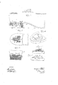
2c vantages-Will clearly appear from the spetEhe nature of the invention and its adcificdescription following. I 1 1 Reference is to be had to the accompany ing drawingsforming a part of this specification in which similar reference characters I indicate corresponding 'parts in all the views I Figure 1 1s a side elevation partly in sec-' 'tion of a portion of a shoe having my improved'heel thereon; v
Fig. 2 is an inverted-plan viewof a portion of the shoe and the permanent heel portion I .Fig. 3 is a transv ers e vertical section on the line. 33, Fig. 1;
Fig. dis a perspective view of the rubber heel of said rubber heel;
Fig. 6 is a side elevation of the rubber heel.
4 My improved heel is adap ed be l plied to any ordinary boot or shoe indicated the letter A. a In carrying out my invention the permanent heel 10 may be of any approved construction and material, there .being indicated a top lift 12 and an under lift or second lift 11. In the permanent heel I produce a depression designated by the numeral 13 and generally of keystone form with the broader end toward the front.
. The material of 'the permanent heel at the depressio at the rear end and a .p r-
tion of t e sides of the recess overlaps in the form of flanges 14:, whereby to give the recess an undercutfomn, -e2goept at the front 5' is a partly sectional front elevation flange 21 is of slightly less thickness than the Patented Aug. 21, 191?.
portion thereof, as indicated at 15. More- 1 over, it will be observed from Fig. 2 that the I forward ends of the side flanges 14: present transverse shoulders 16; the purpose of which will presently appear.
My improved rubber heel to conform to the described formation of the permanent heel 10, for which purpose a block or projection 18 is produced thereon inward at all sides from the'edges of the heel and generally of keystone shape. If desired, the
'projection'1'8 may be reinforced by transverse reinforcing elements 19. At the rear portion, the projection 18 is made T-shape in transverse section, being"- undercut or channeled as at '20 across the rear end and extending alongthe sides thereof short of the front end, thereby producing a flange 21. The forward terminals of the'channel or undercut 20 produces transverse shoul ders 22 on the block 18 beneath the flange 21 and these shoulders, when the rubber heel 17 is secured in positiornare disposed opposite and in frictional engagement with sion 13 at the front of the latter and for-. ward of the side flanges 14, the. heel 17 being bent and otherwise-manipulated in a manner that will be obvious; To pass the flange 21 beneath .the flanges 14, the said depth of the undercut 15 in the heel 10 in order that the said flange '21 will not bind or buckle in being moved into position. Also, the space between the side flanges lfl on any given transverse line is slightly less than the Width of the shank 25 of the projection 18 at the T-shaped portion thereof on a corresponding line; the result is that the flanges 14- compress the rubber at the shank 25 giving a firm holding engagement between the designatedgenerally by the numeral 17 is made of'a shape rubber heel and the permanent-heel in addition to the actual interengagement due to the channel 20 and flanges 14:. When the flange 21 is fully entered in the undercut 15,
the orw ard portion of the projection 18 is sprung into the depression 13' s that the op! posed shoulders 16 and 22 posit vely pre:
vent displacement in the plane of the heel rearwardly While the opposed front walls 23, 24 perform a similar oflice for preventing displacement of the rubber heel in a forward direction. Thus, the rubber heel is secured without the employment of ad ventitious fastening means and positively held against displacement or detachment while it will be seen that said rubber heel may be readily removed by prying its front end outwardly until the described entering steps are reversed.
Having thus described my invention I claim, as new, and'desire to secure by Letters Patent:
1. A boot or shoe heel comprising a permanent heel having a recess therein of general keystone form, and bordered at the four sides by the material of the said heel, said material overlapping at the rear end and sides of the recess to give the latter an un- 'dercut form for a portion thereof, the for- Ward ends of the overlapping side portions presenting transverse shoulders, and a de tachable rubber heel having at the inner side thereof a locking projection of general keystone shape and positioned to be inward at all sides from the edges of the rubber heel the rear portion of the said projection being T-shaped in cross'section presenting a flange at the sides and at the rear, the forward por tion of the said projection presenting rearwardly facing, transverse shoulders at the forward end of the said shank opposing and in contact with the transverse shoulders of the permanent heel.
2. A. boot or shoe heel comprising a per manent heel having a recess therein of general keystone form and bordered at the four sides by the material of the said heel, said material overlapping at the rear end and sides of the recess to give the latter an undercut form for a portion thereof, the for Ward ends of the overlapping side portions presenting transverse shoulders; and a detachable rubber heel having at the inner side thereof a locking projection of general keystone shape and positioned to be inward at all sides from the edges of the rubber heel, the rear portion of the said projection being T-shaped in cross section presenting a flange at the sides and at the rear, the shank-of the T at any transverse line drawn therethrough being of slightly greater width than the space between the side flanges of the permanent heel on a corresponding line, and the forward portion of the said projection presenting rearwardly facing transverse shoulders-atthe forward end of the said shank, the side portions of the flange of the rubber heel being snugly slidable in the undercut portion of the recess, 7
GEORGE EDSON GILBERT;
Priority Applications (1)
| Application Number | Priority Date | Filing Date | Title |
|---|---|---|---|
| US16744717A US1237893A (en) | 1917-05-09 | 1917-05-09 | Detachable heel. |
Applications Claiming Priority (1)
| Application Number | Priority Date | Filing Date | Title |
|---|---|---|---|
| US16744717A US1237893A (en) | 1917-05-09 | 1917-05-09 | Detachable heel. |
Publications (1)
| Publication Number | Publication Date |
|---|---|
| US1237893A true US1237893A (en) | 1917-08-21 |
Family
ID=3305710
Family Applications (1)
| Application Number | Title | Priority Date | Filing Date |
|---|---|---|---|
| US16744717A Expired - Lifetime US1237893A (en) | 1917-05-09 | 1917-05-09 | Detachable heel. |
Country Status (1)
| Country | Link |
|---|---|
| US (1) | US1237893A (en) |
-
1917
- 1917-05-09 US US16744717A patent/US1237893A/en not_active Expired - Lifetime
Similar Documents
| Publication | Publication Date | Title |
|---|---|---|
| US1237893A (en) | Detachable heel. | |
| US2436139A (en) | Stair cover | |
| US788160A (en) | Sole for boots or shoes. | |
| US415181A (en) | Half to john gernert | |
| US2331563A (en) | Brake shoe | |
| US1947840A (en) | Top lift attachment | |
| US1479421A (en) | Shoe heel | |
| US2167526A (en) | Shoe heel reinforcement | |
| US1470480A (en) | Brake shoe | |
| US991296A (en) | Blading means for turbines. | |
| US930550A (en) | Horseshoe. | |
| US1488513A (en) | Brake shoe | |
| US1820539A (en) | Heel | |
| US421168A (en) | Boot or shoe heel fastening | |
| USD27585S (en) | Design for a shoe-vamp | |
| US909015A (en) | Brake-shoe. | |
| US915119A (en) | Brake-shoe. | |
| US1147526A (en) | Arch-supporting shank for shoes. | |
| US1145121A (en) | Shoe-ornament fastener. | |
| US482377A (en) | Artificial tooth | |
| US1939920A (en) | Resilient tread for shoe bottoms | |
| US250974A (en) | Feedebick eichaedson | |
| US1098142A (en) | Protector for heels and soles of boots and shoes. | |
| US457394A (en) | Heel-protector | |
| US279758A (en) | Adjustable horseshoe |