US1237755A - Draft-gear. - Google Patents
Draft-gear. Download PDFInfo
- Publication number
- US1237755A US1237755A US10816616A US10816616A US1237755A US 1237755 A US1237755 A US 1237755A US 10816616 A US10816616 A US 10816616A US 10816616 A US10816616 A US 10816616A US 1237755 A US1237755 A US 1237755A
- Authority
- US
- United States
- Prior art keywords
- casing
- movement
- drawbar
- gear
- pulling
- Prior art date
- Legal status (The legal status is an assumption and is not a legal conclusion. Google has not performed a legal analysis and makes no representation as to the accuracy of the status listed.)
- Expired - Lifetime
Links
- 230000007246 mechanism Effects 0.000 description 18
- 238000009432 framing Methods 0.000 description 16
- 230000035939 shock Effects 0.000 description 9
- 230000008261 resistance mechanism Effects 0.000 description 7
- 238000010276 construction Methods 0.000 description 6
- 238000010521 absorption reaction Methods 0.000 description 3
- 230000006835 compression Effects 0.000 description 3
- 238000007906 compression Methods 0.000 description 3
- 230000000694 effects Effects 0.000 description 3
- 239000000945 filler Substances 0.000 description 3
- 230000003014 reinforcing effect Effects 0.000 description 3
- 235000008733 Citrus aurantifolia Nutrition 0.000 description 1
- 102100030624 Proton myo-inositol cotransporter Human genes 0.000 description 1
- 101710095091 Proton myo-inositol cotransporter Proteins 0.000 description 1
- 235000011941 Tilia x europaea Nutrition 0.000 description 1
- 239000004571 lime Substances 0.000 description 1
- 238000004519 manufacturing process Methods 0.000 description 1
Images


Classifications
-
- B—PERFORMING OPERATIONS; TRANSPORTING
- B61—RAILWAYS
- B61G—COUPLINGS; DRAUGHT AND BUFFING APPLIANCES
- B61G9/00—Draw-gear
- B61G9/04—Draw-gear combined with buffing appliances
- B61G9/10—Draw-gear combined with buffing appliances with separate mechanical friction shock-absorbers
Definitions
- y invention consists of an improvement in draft gears of the general class utilizing springs and friction shoes in connection with centrally arranged expanding wedge mechanism, operable upon butting or pulling, to effect resistance to such strains through the mechanism inclosed within an embracing cylinder or casing.
- the particular objects in view are to provide, in a gear of this type, means whereby the gear may be mounted within the usual or any standard car framing and be capable of operation in either bufiing or pulling, With out exceeding the normal maximum extent of movement of the drawbar in pulling, while permitting of a considerable additional movement in bufling.
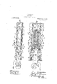
- Figure 1 is a longitudinal vertical sectional view through the complete gear as assembled, the parts being shown in normal by the section line I. I. of Fig. 2.
- Fig. 2 is a corresponding horizontal sectional view, indicated by the line II. II. of Fig. 1.
- Figs. 3 and 4 are cross sectional views, indicated by the lines III. III. and IV. IV. respectively of Fig. 1. v
- Fig. 5 is a view corresponding to. Fig. 2, but showing the gear extended to its limit of movement in pulling. 1
- Fig. 6 is a similar view,'showing the gear compressed, as in bufiing.
- Fig. 7 is a'view similar to Fig. 1, showing a modified construction and arrangement of the friction gear mechanism and casing, in-
- Fig. 8 is a view similar to Fig. 2, showing the construction illustrated in Fig. 7 in horizontal section, indicated by .the line VIII. VIII. of Fig. 7 I
- Sheets 1 and 2 represents the drawbar of the coupler connected with the frontend portions of a U-shaped yoke 3 by a transverse bolt or key 4, which extends through slots 5 in thefront portions. thereof, and through slots 6 in the center sills 7 of the car framing at each side.
- Slots 5 are of suflicient' length to permit of backward independent movement of the bolt 4 in buffing, and slots 6, extending backwardly and forwardly of the bolt 4 in normal position, provide for the desired range of movement in either direction.
- the center sills 7 are reinforced, preferably co-extensive with the length of slots 6,
- members 8 riveted to the center sills, as shown, members 8 also providing bearing abutments for thefront portion of the fric- .sponds in degree of slope pacity of say- 18,000 pounds and in the normal positionof the'ge'ar is under sufficient tension to maintain the parts of the gear in close fitting engagement.
- Casing 10 is providedwith laterally extending lugs 13, which engage against the rear end portions of reinforcing members 8 in pulling, and is also provided with laterally extending supportingand guiding lugs 14 for the yoke member 3.
- Said member extends around across and beyond the inner end ofthe casing by means of a connecting member15, and is preferably provided with a reinforcing. filler plate 16 secured to it in any suitable manner.
- a transverse center block abutment 17 Fixedly mounted between the center sills7, 7, by rivets or otherwise.
- a central wedgeblock or buffer pressure bar 18 bears backwardly by its stem extension 19 agains'tthe front face of said abutment, and is provided with a wedge terminal 20 of pyramidal or coniform shape or other suitable construction, the face of which correto the inner face of expanding wedges 21.
- any suitable wedge mechanism may be utilized which is adapted to expand or distend the f riction shoes within the casing and against the inner sides thereof, and to, at the same time, compress the, spring 12, upon forward movement being imparted to the, central T wedgebythe 'yoke3 in pulling, orrearward movement being imparted to the casing by th'e'coupler. drawbar, in buffing.
- middle portion a bearing shoulder, against which thefillcr plate 16 engages pulling
- the gear may be supported in any suitable manner, as by a plate 25.
- the coupler 2'and bar 4 will draw the central wedge forwardly against the resistance of the friction mechanism within the fixedly held casing 10 until the strain is absorbed, which ordinarily is'within the maximum hmit above referred to, and not exceeding the length of the slots 6 forwardly of the cross bar.
- the spring 12 will be first partially compressed, bolt 41 passing freely back through slots 5, 5, and 6,6, and simultaneously effecting an expansion of the wedge mechanism and resulting friction, central wedge 18 being in abutting engagement against abutment 17.
- Backward movement of the casing away from the abutting engagement with the inner ends of members 8 is to substantially the same degree of movement until the inner open end of the casing makes abutting engagement against the face-of filler plate 16.
- Such movement or travel may be variable, depending upon best-rains to be absorbed in bufiing, and s ould be suflicient to effect absorption of the-maximum strains.
- a draft gear of the class described having a rearwardly movable casing, a drawbar in abutting engagement with the casing and movable away therefrom, means opposing
- The'other parts of the construction are forward movement of the casing, movable resistance mechanism within the casing, and means connecting the drawbar with the cas ing adapted to providefor a limited extent of movement of said resistance mechanism within .the casing in pulling and a relatively increased movement of the casing in relation to the resistance mechanism in buffing.
- a draft gear of the class described having a rearwardly movable casing held agail'ist' forward movement, a drawbar movable rearwardly with the casing and forwardly independent thereof, forwardly movable resistance mechanism within the casing embodying a distending element held against rearward movement, and means 3.
- a draft gear of the class described having a rearwardly movable casing held against forward move1nent, a drawbar movable rearwardly with the casing and forwardly independent thereof, forwardly movable resistance mechanism within the casing held against rearward movement, and an element connecting the casing and resistance mechanism with the drawbar with clearance providing for a limited extent ofmovement of the drawbar and'said element and the resistance mechanism in pulling and an increased movement of the drawbar and casing with relation to the re sistance mechanism in bufiing.
- a casing provided with shock absorbing mechanism in abutting engagement with the car framing and movable away from such engagement, a longitudinally movable drawbar having a transverse bolt slidably mounted in the car framing andhaving apredetermined limit of movement in pulling and capable of exceeding such mo ement in bufiing, and a yoke embracing the casing and in slotted engagement with said bolt.
- a longitudinally movable drawbar having a transverse bolt slidably mounted in the car framing and having a predetermined limit of movement in pulling and capable of exceeding such movement in buffing and a, yoke embracing the casing and in slotted engagement with said bolt, the drawbar and voke being adapted to effeet compression of the shock absorbing mechanism in one direction of movement or the other.
- a ca sing provided with shock absorbingmechanism in abutting engagement with the car framing and movable away from such engagement, a longitudinally movable drawbar having a transversediiol't slidably mounted in the carframing, and having a predetermined limit of movement in pulling and capable of exceeding such movement in gbufling and a yoke embracing the casing positively engaging said distending element connecting the casing and resistance mechaviding for rearward movement of the drawbar and casing independent of said means.
- the drawbar and yoke being adapted toef: fect compression of the shock absorbing mechanism in one direction of movement or the other and in variable degrees.
- a yoke embracing the casing and in slotted engagement with said boltyfrietion creating mechanism within the casing, I a central wedge operable to effect expansion of the friction creating mechanism, and an opposing abutment therefor.
Landscapes
- Engineering & Computer Science (AREA)
- Mechanical Engineering (AREA)
- Braking Arrangements (AREA)
Description
J F. COURSON.
DRAFT GEAR. I APPLICATION FILED JULY 6. 1916.
Patented Aug. 21,1917.
3 SHEETS-SHEET 1;
J. F. coufisom DRAFT GEAR. APPLICATION FILED JULY 8. ma.
3 SHEETSSHEET 2.
Patented Aug. 21, 1917.
J. F. COURSON.
DRAFT GEAR. APPLICATION FILED mu 8,1916.
Patented Aug. 2L 1917 3 SHEETS-SHEET 3.
Warren snares Parana orricn.
1 JOHN F. COURSON, OF PITCAIRN, PENNSYLVANIA.
DRAFT-GEAR.
Application filed July 8, 1916. Serial No.108,166.
To all whom it may concern:
Be it known that I, JOHN F. COURSON, a
citizen of the United States, residing at Pitv cairn, in the county of Allegheny and State of Pennsylvania, have invented certain new and useful Improvements in Draft-Gears, of which the following is a specification.
y invention consists of an improvement in draft gears of the general class utilizing springs and friction shoes in connection with centrally arranged expanding wedge mechanism, operable upon butting or pulling, to effect resistance to such strains through the mechanism inclosed within an embracing cylinder or casing. Y v
The particular objects in view are to provide, in a gear of this type, means whereby the gear may be mounted within the usual or any standard car framing and be capable of operation in either bufiing or pulling, With out exceeding the normal maximum extent of movement of the drawbar in pulling, while permitting of a considerable additional movement in bufling.
Ordinarily, in gears of this type, movement in pulling is to the same extent as in buliing, and subject to ordinary restrictions, such pulling and bufling movement being limited to any desired maximum. By my improvement it is designed to provide a gear which is capable of absorbing the usual normal or expected pulling strains within such limit of range of movement of the drawbar,
' which ordinarily do not utilize but a portion of the entire capacity of the gear, and to provide for a considerable longer movement of the drawbar in butting, with a proportionately increased desirable resistance.
'lhese objects are secured by so mounting the resistaiice member of the gear within the car framing. and so connecting it with the drawbar by means adapted to utilize the resisting action in pulling to the desired degree, and the resistance in butting to a considerably greater degree in connectlon with corresponding additional movement.
The several objects in view. are accomplished, in certain preferred forms of the apparatus, as more fully here nafter de- Specification of Letters Patent.
extended position, as indicated scribed and illustrated in the accompanying drawings, in which i Figure 1 is a longitudinal vertical sectional view through the complete gear as assembled, the parts being shown in normal by the section line I. I. of Fig. 2.
Fig. 2 is a corresponding horizontal sectional view, indicated by the line II. II. of Fig. 1.
Figs. 3 and 4 are cross sectional views, indicated by the lines III. III. and IV. IV. respectively of Fig. 1. v
Fig. 5 is a view corresponding to. Fig. 2, but showing the gear extended to its limit of movement in pulling. 1
Fig. 6 is a similar view,'showing the gear compressed, as in bufiing.
Fig. 7 is a'view similar to Fig. 1, showing a modified construction and arrangement of the friction gear mechanism and casing, in-
dicated by the line VII. VII. of Fig. 8.
Fig. 8 is a view similar to Fig. 2, showing the construction illustrated in Fig. 7 in horizontal section, indicated by .the line VIII. VIII. of Fig. 7 I
In the drawings, referring to Sheets 1 and 2, 2 represents the drawbar of the coupler connected with the frontend portions of a U-shaped yoke 3 by a transverse bolt or key 4, which extends through slots 5 in thefront portions. thereof, and through slots 6 in the center sills 7 of the car framing at each side.
Slots 5 are of suflicient' length to permit of backward independent movement of the bolt 4 in buffing, and slots 6, extending backwardly and forwardly of the bolt 4 in normal position, provide for the desired range of movement in either direction.
The center sills 7 are reinforced, preferably co-extensive with the length of slots 6,
Patented Aug. 21, 1917.
with inner and outer reinforcing members 5,
9, respectively, riveted to the center sills, as shown, members 8 also providing bearing abutments for thefront portion of the fric- .sponds in degree of slope pacity of say- 18,000 pounds and in the normal positionof the'ge'ar is under sufficient tension to maintain the parts of the gear in close fitting engagement.
i Saidface's, 10., of terminal 20, and the inner contacting facesv of wedges 21, taper inwardlytoward; the longitudinal center of the gear at 'such an'angle as to produce a maximum expansion, with resulting free release; Wedges .or. wedge blocks 21 bear outwardly against the inner faces of a plurality of 'friction shoes 22 arranged in an annular series wlthin the casing 10, and are adapted tofrictionally engage the inner surface thereof. z Shoes 22 are provided at their other ends with inwardly disposed wedge faces 23,
against which. bear fthe facesof a pressure transmitting wedge 24: in abutting engagement with the. ends of wedge blocks 21, whereby to expand the friction shoes 22 equally throughout their-length- I It will be understood, however, that any suitable wedge mechanism may be utilized which is adapted to expand or distend the f riction shoes within the casing and against the inner sides thereof, and to, at the same time, compress the, spring 12, upon forward movement being imparted to the, central T wedgebythe 'yoke3 in pulling, orrearward movement being imparted to the casing by th'e'coupler. drawbar, in buffing.
' Central wedge 18 provides by its enlarged.
middle portion a bearing shoulder, against which thefillcr plate 16 engages pulling,
due to tliev reduced cross sectiongof ,the extended stem 19. The gear may be supported in any suitable manner, as by a plate 25.
The construction and operation of the device will be readily understood from the foregoin description.
In pu ing, the coupler 2'and bar 4 will draw the central wedge forwardly against the resistance of the friction mechanism within the fixedly held casing 10 until the strain is absorbed, which ordinarily is'within the maximum hmit above referred to, and not exceeding the length of the slots 6 forwardly of the cross bar.
In bufling, the spring 12 will be first partially compressed, bolt 41 passing freely back through slots 5, 5, and 6,6, and simultaneously effecting an expansion of the wedge mechanism and resulting friction, central wedge 18 being in abutting engagement against abutment 17. Backward movement of the casing away from the abutting engagement with the inner ends of members 8 is to substantially the same degree of movement until the inner open end of the casing makes abutting engagement against the face-of filler plate 16.
Thereupon, continued further movement will thrust the plate and yoke members 3 baclavardly with the casing until the rear cross member 15 comes close to or into engagement with-the face of abutment 17 during which time the resistance of the friction mechanism and'the compression spring 12 is steadily increasing, as indicated in Fig. 6.
By this means a .very considerably longer longitudinal movement may be impartedto the gear in bufiing than in pulling, which movement may be varied as desired, depending on the length and extent of projection of the stem 19 inwardly beyond cross member 15 before it engages abutment 17.
Such movement or travel may be variable, depending upon best-rains to be absorbed in bufiing, and s ould be suflicient to effect absorption of the-maximum strains.
In the arrangement shown in Figs. 7 and 8, substantially thesameconstruction and operation is shown andnprovided for, except that the casing 10 of the strain-absorbing member is reversed in position, its closed end being embraced by-f theircar end 15 of the (i nism with the drawbar with clearance proclearance for the rear portion of the yoke and its filler block 16 which may thus pass backwardly independently of the casing in buffing.-
substantially thesame as already described, and indicated by the same numerals having the exponent a. a r
In either bufling or pulling, the operation already described is substantially the same, providing for absorption of the pulling shocks within a predetermined limit of movement, and absorption of the bufiing shocks without such limitation. F
The advantagesof the invention will be readily understood. and appreciated by all those familiar with this'class of mechanism. It provides a construction which is simple and compact, economical to manufacture, and capable of performing its functions within prescribed limitations as to pulling, while permitting the much greater shocks of buflinu to be absorbed without such lime itation of travel.
The invention may be utilized without necessarily restricting it to theexact strainabsorbin member illustrated orto other details, an may be varied in such features by the skilled mechanic within the scope of the appended claims.
What I claim is:
1. A draft gear of the class described having a rearwardly movable casing, a drawbar in abutting engagement with the casing and movable away therefrom, means opposing The'other parts of the construction are forward movement of the casing, movable resistance mechanism within the casing, and means connecting the drawbar with the cas ing adapted to providefor a limited extent of movement of said resistance mechanism within .the casing in pulling and a relatively increased movement of the casing in relation to the resistance mechanism in buffing.
2. A draft gear of the class described having a rearwardly movable casing held agail'ist' forward movement, a drawbar movable rearwardly with the casing and forwardly independent thereof, forwardly movable resistance mechanism within the casing embodying a distending element held against rearward movement, and means 3. A draft gear of the class described having a rearwardly movable casing held against forward move1nent, a drawbar movable rearwardly with the casing and forwardly independent thereof, forwardly movable resistance mechanism within the casing held against rearward movement, and an element connecting the casing and resistance mechanism with the drawbar with clearance providing for a limited extent ofmovement of the drawbar and'said element and the resistance mechanism in pulling and an increased movement of the drawbar and casing with relation to the re sistance mechanism in bufiing.
4. In combination with car framing, a casing provided with shock absorbing mechanism in abutting engagement with the car framing and movable away from such engagement, a longitudinally movable drawbar having a transverse bolt slidably mounted in the car framing andhaving apredetermined limit of movement in pulling and capable of exceeding such mo ement in bufiing, and a yoke embracing the casing and in slotted engagement with said bolt.
5. In combination with car framing, a casing provided with shock absorbing mechanism in abutting engagement with the car framing and movable away from suchengagement, a longitudinally movable drawbar having a transverse bolt slidably mounted in the car framing and having a predetermined limit of movement in pulling and capable of exceeding such movement in buffing and a, yoke embracing the casing and in slotted engagement with said bolt, the drawbar and voke being adapted to effeet compression of the shock absorbing mechanism in one direction of movement or the other.
6. In combination with car "framing, a ca sing provided with shock absorbingmechanism in abutting engagement with the car framing and movable away from such engagement, a longitudinally movable drawbar having a transversediiol't slidably mounted in the carframing, and having a predetermined limit of movement in pulling and capable of exceeding such movement in gbufling and a yoke embracing the casing positively engaging said distending element connecting the casing and resistance mechaviding for rearward movement of the drawbar and casing independent of said means.
and in slotted engagement with said bolt, the drawbar and yoke being adapted toef: fect compression of the shock absorbing mechanism in one direction of movement or the other and in variable degrees.
7. In combination with car framing, a casing in abutting engagement with the car framing and movable away from such engagement, shock absorbing mechanism within the casing, a longitudinally movable drawbar having a-transverse bolt slidably mounted in the car framing and having a I greater movement in bufling than in pulling,
a yoke embracing the casing and in slotted engagement with said boltyfrietion creating mechanism within the casing, I a central wedge operable to effect expansion of the friction creating mechanism, and an opposing abutment therefor.
8. In'combination With car framing having forward stop abntments, a cylindrical caslng engaging said abutments, a rear abut- 1nent,a drawbar having a transverse bolt in slotted engagement with the framing and having a greater movement in bufiing than in pulling, a yoke embracing the casing and in slotted engagement With the transverse drawbar bolt, a spring and friction creating mechanism 'Within the casing and, a central Wedge engaging said rear abutment and friction creating mechanism respectively.
In testimony whereof I hereunto aflix 'my slgnature 1n the presence of a wltness.
JOHN F. COURSON. W itne'ss:
C. M. CLARKE.
Priority Applications (1)
| Application Number | Priority Date | Filing Date | Title |
|---|---|---|---|
| US10816616A US1237755A (en) | 1916-07-08 | 1916-07-08 | Draft-gear. |
Applications Claiming Priority (1)
| Application Number | Priority Date | Filing Date | Title |
|---|---|---|---|
| US10816616A US1237755A (en) | 1916-07-08 | 1916-07-08 | Draft-gear. |
Publications (1)
| Publication Number | Publication Date |
|---|---|
| US1237755A true US1237755A (en) | 1917-08-21 |
Family
ID=3305572
Family Applications (1)
| Application Number | Title | Priority Date | Filing Date |
|---|---|---|---|
| US10816616A Expired - Lifetime US1237755A (en) | 1916-07-08 | 1916-07-08 | Draft-gear. |
Country Status (1)
| Country | Link |
|---|---|
| US (1) | US1237755A (en) |
Cited By (1)
| Publication number | Priority date | Publication date | Assignee | Title |
|---|---|---|---|---|
| US2451415A (en) * | 1943-07-19 | 1948-10-12 | Nat Malleabie And Steel Castin | Railway car draft gear |
-
1916
- 1916-07-08 US US10816616A patent/US1237755A/en not_active Expired - Lifetime
Cited By (1)
| Publication number | Priority date | Publication date | Assignee | Title |
|---|---|---|---|---|
| US2451415A (en) * | 1943-07-19 | 1948-10-12 | Nat Malleabie And Steel Castin | Railway car draft gear |
Similar Documents
| Publication | Publication Date | Title |
|---|---|---|
| US2527589A (en) | Cushioning mechanism for railway vehicles | |
| US1237755A (en) | Draft-gear. | |
| US2184936A (en) | Cushioning mechanism | |
| US3031089A (en) | Central buffing and draft gear | |
| US1183837A (en) | Friction draft-rigging. | |
| US2474919A (en) | Draft rigging shock absorber | |
| US1300700A (en) | Drait-gbar | |
| US1947316A (en) | Draft rigging | |
| US1169434A (en) | Friction draft-rigging. | |
| US1663992A (en) | Friction shock-absorbing mechanism | |
| US1241156A (en) | Friction draft-gear. | |
| US1319210A (en) | Draft-gear | |
| US839203A (en) | Draft-gear for railway-cars. | |
| US677272A (en) | Draft-gear for railway-cars. | |
| US566935A (en) | Draft-rigging | |
| US773155A (en) | Friction draft-gear. | |
| US773387A (en) | Draft and buffing rigging. | |
| US1237759A (en) | Draft-gear. | |
| US1683822A (en) | Shock-absorbing mechanism | |
| US1368988A (en) | Draft-geak | |
| US1243756A (en) | Friction draft-gear. | |
| US1123853A (en) | Draft-gear. | |
| US1747482A (en) | Friction shock-absorbing mechanism | |
| US1202008A (en) | Friction-buffer. | |
| US1162574A (en) | Draft-gear. |