US1237726A - Pressing and steaming iron. - Google Patents
Pressing and steaming iron. Download PDFInfo
- Publication number
- US1237726A US1237726A US15983917A US15983917A US1237726A US 1237726 A US1237726 A US 1237726A US 15983917 A US15983917 A US 15983917A US 15983917 A US15983917 A US 15983917A US 1237726 A US1237726 A US 1237726A
- Authority
- US
- United States
- Prior art keywords
- iron
- water
- steam
- pressing
- pipe
- Prior art date
- Legal status (The legal status is an assumption and is not a legal conclusion. Google has not performed a legal analysis and makes no representation as to the accuracy of the status listed.)
- Expired - Lifetime
Links
- XEEYBQQBJWHFJM-UHFFFAOYSA-N Iron Chemical compound [Fe] XEEYBQQBJWHFJM-UHFFFAOYSA-N 0.000 title description 96
- 229910052742 iron Inorganic materials 0.000 title description 49
- 238000010025 steaming Methods 0.000 title description 2
- XLYOFNOQVPJJNP-UHFFFAOYSA-N water Substances O XLYOFNOQVPJJNP-UHFFFAOYSA-N 0.000 description 21
- 238000010438 heat treatment Methods 0.000 description 6
- 235000000396 iron Nutrition 0.000 description 6
- 239000000463 material Substances 0.000 description 5
- 238000007599 discharging Methods 0.000 description 4
- 238000002485 combustion reaction Methods 0.000 description 3
- 238000009833 condensation Methods 0.000 description 3
- 230000005494 condensation Effects 0.000 description 3
- 238000010276 construction Methods 0.000 description 3
- 150000002505 iron Chemical class 0.000 description 2
- 229910001369 Brass Inorganic materials 0.000 description 1
- 244000052616 bacterial pathogen Species 0.000 description 1
- 239000010951 brass Substances 0.000 description 1
- 239000004020 conductor Substances 0.000 description 1
- 230000008878 coupling Effects 0.000 description 1
- 238000010168 coupling process Methods 0.000 description 1
- 238000005859 coupling reaction Methods 0.000 description 1
Images

Classifications
-
- D—TEXTILES; PAPER
- D06—TREATMENT OF TEXTILES OR THE LIKE; LAUNDERING; FLEXIBLE MATERIALS NOT OTHERWISE PROVIDED FOR
- D06F—LAUNDERING, DRYING, IRONING, PRESSING OR FOLDING TEXTILE ARTICLES
- D06F75/00—Hand irons
- D06F75/08—Hand irons internally heated by electricity
- D06F75/10—Hand irons internally heated by electricity with means for supplying steam to the article being ironed
- D06F75/12—Hand irons internally heated by electricity with means for supplying steam to the article being ironed the steam being produced from water supplied to the iron from an external source
Definitions
- This invention relates to pressing irons, such as are used by tailors and particularly to self heating irons.
- the object of this invention is to provide a pressing iron particularly designed for use intailor shops where clothes are pressed and sponged, the iron being so constructed that it crate steam, which steam will be forced through perforations into the material being pressed, thus doing away with the necessity of sponging or otherwise dampening thematerialbeing ironed.
- a further object of the invention is to provide means on the handle of the iron for controlling the flow -of waterto the steam generator.
- a further object is to improve the details of construction of irons of this character .by providing means whereby air for combustion may enter the iron, ,providing an improved form of burner therein and providing for an improved form of steam generator.
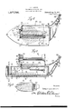
- FIG. 1 is a lperspective view of an iron constructed in accordance with my invention
- Fig. 2 is a top plan view of the iron illustrated in Fig. 1;
- Fig. 3 is a longitudinal sectional view of the iron illustrated in Fig. 2; v
- Fig. 4 is a transverse sectional view on the line 4-4 of Fig. 3;
- Fig. 5 is an underside view of the iron.
- Fig. 6 is a fragmentary elevation of the as and water connections to theiron.
- 10 designates the body of the iron which has approximately the usual form and is iprovided with the upwardly extending hand e supports 11,
- thesev handle supports supporting a rotatable handle 12 which may be made of a'jv suitable material, but is preferably made of non-heat conducting material.
- the supports 1l are mounted upon a cover plate 13, which is attached to the body of the iron in any suitable manner and the side walls of the' iron and the bottom 14 are hollow, so as to provide a steam space or chamber 15, extending through the walls of the iron and through the bottom thereof.
- the inner wall of this steam space may be supported from the outer wall of the steam space 'by integral webs or pins 16.
- the bottom of the iron is formed with a plurality of openings 17 leading from the steam space, these perforations 'or openings being relatively,small and being .disposed uniformly over the face of the bottom.
- the upper edges of the side walls are cut away at a plurality of points, as at 18 vto permit hot air to'pass and products of combustion to escape from the interior of the iron and preferably the side walls are provided with a plurality of outwardly extending tubes 19 through which air may pass into the interior of the iron for the purpose of supporting combustion.
- a pair of burner pipes 20, which are preferably angular in cross section and formed upon their inner faces with downwardly opening perforations 21,'where-
- I provide the water pipe 25 which is connected to any suitable source of water as, for instance, the reservoir 26, this pipe 25 being made of iexible material and extending down beside the pipe 23 and preferably being connected thereto by a wrapping 28.
- a flexible pipe 25 extends downward to the iro-n andr connects to a pipe 29 which extends over the cover 13 and at its end is connected by an elbow 30 to a valve casing 31, from which extends a pipe 32 leading downward through the cover plate into the interior of the iron where it is connected to one end of a coil of brass pipe 33, this preferably bei-ng a inch pipe.
- This pipe 33 is bent to form a coil 34 which is disposed above the burner tubes 20 and the other Vend of the coil is extended to a T coupling 35 which in its turn is connected to two branch pipes 36 extending into the space l5 formed in the side Walls of the iron.
- the object of this invention is to provide for initially heating the water as it enters the iron and then discharging this heated water or steam into the space within the wall of the iron where the steam will be more highly expanded orwhere the water will be completely vaporized, if the water in the coil is not turned to steam.
- a valve having a handle 38 shown as radially disposed.
- Mounted upon one end of the handle 12 is an eccentric disk 39 pivotally connected to an arm 40 which in turn is pivotally connected to a second arm 40a which is operatively connected to the handle 38.
- the valve may be shifted. to increase, diminish, or entirely cut 0H the flow of water from the pipe 29 to the pipe 32.
- My improved Ipressing iron does away with the necessity of using Sponges or damp cloths and, therefore, saves considerable time and labor. Furthermore, its use is much more sanitary than the use of Sponges or like dampening means, as the water used is always fresh and not used over and over again, thus accumulating dirt, and the superheated steam that is forced into the interstices of the material being pressed tends to kill germs and thoroughly disinfect the material. As soon as the valve 37 is opened, it allows a flow of water in any quantity desired to pass into the coil 34 which is dis posed directly 4over the burners and is always hot. This coil immediately begins to generate steam and this steam Hows into the hollow chambers of the iron and passes out through the perforations in the body of the iron to the garment which is being sponged and pressed.
- the webs or pins 16de not merely act to support the inner wall upon the outer wall of the iron but have a very important additional function. These pins or webs 16 act to conduct the heat from the inside of the iron to the pressing surface of the iron. If it were not for the fact that these webs or -pins conducted the heat to the pressing surface of the iron it would be impossible to heat the bottom of the iron sufficiently for the iron to have any practical value. These pins or webs conduct the heat from the inner wall of the bottoni to the outer wall thereof.
- a pressing iron of the character described having a body formed with a bottom and side walls, the bottom and side walls being chambered and communicating with each other and the bottom being formed with downwardly opening perforations, a gas burner mounted within the iron and having jet orifices discharging downward, the burner being adapted to be connected to a source of gas, a water pipe entering the interior of the iron. and extending over said burner and having oppositely eX- tending branches opening into the chamberedwall of the iron, said wall being provided with air inlet openings.
- a pressing iron ofthe character described havingw a chambered bottom and chambered side walls, the bottom being formed with downwardly opening perforations and the side walls having air openings extending entirely through the side walls and having heat outlet openings, a cover detachably mounted upon the side walls, a handle mounted on the cover, a burner disposed within the hollow interior of the iron and having orifices discharging upward and downward, a header to which the burner is connected, a gas pipe Aconnected to the header, a water pipe disposed upon the exterior of the cover and extending from the rear end of the iron to theA forward end thereof and connectible to a water supply, said water pipe extending downward into the interior of the iron and discharging into a heating coil disposed within the iron and above the burner, the heating coil at its exit the valve may be actuated to control the end being provided with branches leading Water supply.
Landscapes
- Health & Medical Sciences (AREA)
- Public Health (AREA)
- Engineering & Computer Science (AREA)
- Textile Engineering (AREA)
- Irons (AREA)
Description
C. L. TAYLOR.
PREssmG AND stimme IRON.
APPLICATION FILED APR. .4.. IBI
sneu l Patented Aug.
2 S IIE E TS CHARLES Lows Tamm C. L. TAYLOR.
PRESSING AND STEAMING IRON.
APPLlcAnon min APR.4.19H.
Patented Aug. 21, 1917.
2 SHEETS-SHEET 2.
CHHRLES Lows THYLOR.
@cocoa anun,
l T lall whom z't-may concern:
CHARLES LOUIS TAYLOR, OF UTICA, NEW YORK.
PnEssINe AND STEAMING IRON. y l Patented Aug. 21, 191'?. Application mea Apri14,1917. serial No. 159,839.
aaeaaae.
Be it known that CHARLES LoUIs TAYLOR, a citizen ofthe United States, residing at Utica, in the county of @neida and State of New York, has invented certain new and useful Improvements in Pressing and Steaming Irons, of which the following is a specil ication, reference being had to the'acco-mpanying drawings.
This invention relates to pressing irons, such as are used by tailors and particularly to self heating irons. l
The object of this invention is to provide a pressing iron particularly designed for use intailor shops where clothes are pressed and sponged, the iron being so constructed that it crate steam, which steam will be forced through perforations into the material being pressed, thus doing away with the necessity of sponging or otherwise dampening thematerialbeing ironed.
A further object of the invention is to provide means on the handle of the iron for controlling the flow -of waterto the steam generator.A
,A further object is to improve the details of construction of irons of this character .by providing means whereby air for combustion may enter the iron, ,providing an improved form of burner therein and providing for an improved form of steam generator.
Other objects will appear in the course of the following description.
My invention is illustrated in the accompanying drawing, in which:
- Figure 1 is a lperspective view of an iron constructed in accordance with my invention;
Fig. 2 is a top plan view of the iron illustrated in Fig. 1;
Fig. 3 is a longitudinal sectional view of the iron illustrated in Fig. 2; v
Fig. 4 is a transverse sectional view on the line 4-4 of Fig. 3;
Fig. 5 is an underside view of the iron; and
Fig. 6 is a fragmentary elevation of the as and water connections to theiron.
Referring to this drawing, 10 designates the body of the iron which has approximately the usual form and is iprovided with the upwardly extending hand e supports 11,
Specification of Letters Patent.
will not only be heated, but will gen-` upon it's upper surface, thesev handle supports supporting a rotatable handle 12 which may be made of a'jv suitable material, but is preferably made of non-heat conducting material. The supports 1l are mounted upon a cover plate 13, which is attached to the body of the iron in any suitable manner and the side walls of the' iron and the bottom 14 are hollow, so as to provide a steam space or chamber 15, extending through the walls of the iron and through the bottom thereof. The inner wall of this steam space may be supported from the outer wall of the steam space 'by integral webs or pins 16. The bottom of the iron is formed with a plurality of openings 17 leading from the steam space, these perforations 'or openings being relatively,small and being .disposed uniformly over the face of the bottom. The upper edges of the side walls are cut away at a plurality of points, as at 18 vto permit hot air to'pass and products of combustion to escape from the interior of the iron and preferably the side walls are provided with a plurality of outwardly extending tubes 19 through which air may pass into the interior of the iron for the purpose of supporting combustion. Supported in the large end of the iron and extending toward the small end thereof are a pair of burner pipes 20, which are preferably angular in cross section and formed upon their inner faces with downwardly opening perforations 21,'where- For the purpose ofsupplying water to the iron, I provide the water pipe 25 which is connected to any suitable source of water as, for instance, the reservoir 26, this pipe 25 being made of iexible material and extending down beside the pipe 23 and preferably being connected thereto by a wrapping 28. A flexible pipe 25 extends downward to the iro-n andr connects toa pipe 29 which extends over the cover 13 and at its end is connected by an elbow 30 to a valve casing 31, from which extends a pipe 32 leading downward through the cover plate into the interior of the iron where it is connected to one end of a coil of brass pipe 33, this preferably bei-ng a inch pipe. This pipe 33 is bent to form a coil 34 which is disposed above the burner tubes 20 and the other Vend of the coil is extended to a T coupling 35 which in its turn is connected to two branch pipes 36 extending into the space l5 formed in the side Walls of the iron.
` The object of this invention is to provide for initially heating the water as it enters the iron and then discharging this heated water or steam into the space within the wall of the iron where the steam will be more highly expanded orwhere the water will be completely vaporized, if the water in the coil is not turned to steam.
For the purpose of controlling the passage of water into the heating coil 34, I provide in the valve casing 31, a valve having a handle 38 shown as radially disposed. Mounted upon one end of the handle 12 is an eccentric disk 39 pivotally connected to an arm 40 which in turn is pivotally connected to a second arm 40a which is operatively connected to the handle 38. By rotation of the handle in one direction or the other, the valve may be shifted. to increase, diminish, or entirely cut 0H the flow of water from the pipe 29 to the pipe 32.
My improved Ipressing iron does away with the necessity of using Sponges or damp cloths and, therefore, saves considerable time and labor. Furthermore, its use is much more sanitary than the use of Sponges or like dampening means, as the water used is always fresh and not used over and over again, thus accumulating dirt, and the superheated steam that is forced into the interstices of the material being pressed tends to kill germs and thoroughly disinfect the material. As soon as the valve 37 is opened, it allows a flow of water in any quantity desired to pass into the coil 34 which is dis posed directly 4over the burners and is always hot. This coil immediately begins to generate steam and this steam Hows into the hollow chambers of the iron and passes out through the perforations in the body of the iron to the garment which is being sponged and pressed.
It will be seen that with my construction there is ample space for the steam to generate and pass out into the clothes and be uniformly distributed throughout the iron, thus increasing the heat of the iron and the heat of the iron in turn increasing the heat of the steam. Vhen it is not desired to use steam but the pressing is to be done with a dry iron, the water need not be allowed to pass into the iron. The iron may be readily connected to or disconnected from the source of gas and water. The device is very simple, can be cheaply made and has the advantages previously stated.
The webs or pins 16de not merely act to support the inner wall upon the outer wall of the iron but have a very important additional function. These pins or webs 16 act to conduct the heat from the inside of the iron to the pressing surface of the iron. If it were not for the fact that these webs or -pins conducted the heat to the pressing surface of the iron it would be impossible to heat the bottom of the iron sufficiently for the iron to have any practical value. These pins or webs conduct the heat from the inner wall of the bottoni to the outer wall thereof.
One very important feature of the construction lies in the fact that all condensation is taken care of, in other words, there is no condensation in this iron. This is where other types of self-heating irons have entirely failed. This iron constructed in'accordance with; this invention has been fully tested and no condensation occurs. It is obvious that' the irons may be made of various weights, from fifteen pounds u'p to any desired weight.
Having described my invention, what I claim is:
1.A pressing iron of the character described, having a body formed with a bottom and side walls, the bottom and side walls being chambered and communicating with each other and the bottom being formed with downwardly opening perforations, a gas burner mounted within the iron and having jet orifices discharging downward, the burner being adapted to be connected to a source of gas, a water pipe entering the interior of the iron. and extending over said burner and having oppositely eX- tending branches opening into the chamberedwall of the iron, said wall being provided with air inlet openings.
2. A pressing iron ofthe character described havingw a chambered bottom and chambered side walls, the bottom being formed with downwardly opening perforations and the side walls having air openings extending entirely through the side walls and having heat outlet openings, a cover detachably mounted upon the side walls, a handle mounted on the cover, a burner disposed within the hollow interior of the iron and having orifices discharging upward and downward, a header to which the burner is connected, a gas pipe Aconnected to the header, a water pipe disposed upon the exterior of the cover and extending from the rear end of the iron to theA forward end thereof and connectible to a water supply, said water pipe extending downward into the interior of the iron and discharging into a heating coil disposed within the iron and above the burner, the heating coil at its exit the valve may be actuated to control the end being provided with branches leading Water supply. 10 into'the chamhered side walls of the iron, In testimony whereof I hereunto affix my a valve controlling the passage of Water' signature in the presence of two Witnemea through the Water tube and having a la- CHARLES LOUIS TAYLOR. dially extending arm, and valve actuated Witnesses: arms operatively connected to each other, WARREN C. TUCKER.
to the valve arm and to the handle whereby A. MARGARET SCHMID.
Priority Applications (1)
| Application Number | Priority Date | Filing Date | Title |
|---|---|---|---|
| US15983917A US1237726A (en) | 1917-04-04 | 1917-04-04 | Pressing and steaming iron. |
Applications Claiming Priority (1)
| Application Number | Priority Date | Filing Date | Title |
|---|---|---|---|
| US15983917A US1237726A (en) | 1917-04-04 | 1917-04-04 | Pressing and steaming iron. |
Publications (1)
| Publication Number | Publication Date |
|---|---|
| US1237726A true US1237726A (en) | 1917-08-21 |
Family
ID=3305544
Family Applications (1)
| Application Number | Title | Priority Date | Filing Date |
|---|---|---|---|
| US15983917A Expired - Lifetime US1237726A (en) | 1917-04-04 | 1917-04-04 | Pressing and steaming iron. |
Country Status (1)
| Country | Link |
|---|---|
| US (1) | US1237726A (en) |
Cited By (6)
| Publication number | Priority date | Publication date | Assignee | Title |
|---|---|---|---|---|
| US2427474A (en) * | 1943-07-31 | 1947-09-16 | August C Purpura | Vacuum hand ironing and drying apparatus |
| US2434136A (en) * | 1944-02-08 | 1948-01-06 | Silex Co | Steaming and pressing iron |
| US2777226A (en) * | 1954-10-06 | 1957-01-15 | Gen Electric | Water and power supply for steam irons |
| US2799100A (en) * | 1954-12-01 | 1957-07-16 | Beachee Products Corp | Steam ironing apparatus |
| US20080189993A1 (en) * | 2007-02-12 | 2008-08-14 | Luis Cavada | Fast Heat / Fast Cool Iron With Steam Boiler |
| US20080189991A1 (en) * | 2007-02-12 | 2008-08-14 | Applica Consumer Products, Inc. | Iron With Actively Cooled Soleplate |
-
1917
- 1917-04-04 US US15983917A patent/US1237726A/en not_active Expired - Lifetime
Cited By (8)
| Publication number | Priority date | Publication date | Assignee | Title |
|---|---|---|---|---|
| US2427474A (en) * | 1943-07-31 | 1947-09-16 | August C Purpura | Vacuum hand ironing and drying apparatus |
| US2434136A (en) * | 1944-02-08 | 1948-01-06 | Silex Co | Steaming and pressing iron |
| US2777226A (en) * | 1954-10-06 | 1957-01-15 | Gen Electric | Water and power supply for steam irons |
| US2799100A (en) * | 1954-12-01 | 1957-07-16 | Beachee Products Corp | Steam ironing apparatus |
| US20080189993A1 (en) * | 2007-02-12 | 2008-08-14 | Luis Cavada | Fast Heat / Fast Cool Iron With Steam Boiler |
| US20080189991A1 (en) * | 2007-02-12 | 2008-08-14 | Applica Consumer Products, Inc. | Iron With Actively Cooled Soleplate |
| US7610701B2 (en) | 2007-02-12 | 2009-11-03 | Applica Consumer Products, Inc. | Iron with actively cooled soleplate |
| US7926208B2 (en) | 2007-02-12 | 2011-04-19 | Applica Consumer Products, Inc. | Fast heat/fast cool iron with steam boiler |
Similar Documents
| Publication | Publication Date | Title |
|---|---|---|
| JP2010512905A (en) | Equipment for supplying superheated water | |
| US1237726A (en) | Pressing and steaming iron. | |
| US1099264A (en) | Flat-iron. | |
| US2230815A (en) | Pressing iron | |
| US1299036A (en) | Pressing apparatus. | |
| US1150355A (en) | Garment-pressing machine. | |
| US1045179A (en) | Pressing and finishing iron. | |
| US2660818A (en) | Handy iron | |
| US1243175A (en) | Garment-steaming device. | |
| US1226516A (en) | Hot-water drum. | |
| US1492892A (en) | Combination drier and cooker | |
| US1201975A (en) | Self-heating sad-iron. | |
| US1880668A (en) | Apparatus for treating and cleaning pile fabric materials | |
| CN110607677A (en) | Multipurpose steam brush with at least two ironing sides | |
| US976571A (en) | Steam pressing and finishing iron. | |
| US2258446A (en) | Pressing iron | |
| US190409A (en) | Improvement in laundry apparatus | |
| US2317261A (en) | Pressing iron | |
| CN104562612B (en) | Integrated garment steamer | |
| US1677573A (en) | Fabric puffer | |
| US25177A (en) | Washing-machine | |
| US1539786A (en) | Pressing machine | |
| US1373879A (en) | Steamer, cleaner, and presser | |
| US342541A (en) | Apparatus for renovating fabrics | |
| US624306A (en) | Electric water-boiler |