US1237669A - Cooling-receptacle. - Google Patents
Cooling-receptacle. Download PDFInfo
- Publication number
- US1237669A US1237669A US10568416A US10568416A US1237669A US 1237669 A US1237669 A US 1237669A US 10568416 A US10568416 A US 10568416A US 10568416 A US10568416 A US 10568416A US 1237669 A US1237669 A US 1237669A
- Authority
- US
- United States
- Prior art keywords
- neck
- receptacle
- porous
- cooling
- porous member
- Prior art date
- Legal status (The legal status is an assumption and is not a legal conclusion. Google has not performed a legal analysis and makes no representation as to the accuracy of the status listed.)
- Expired - Lifetime
Links
Images
Classifications
-
- F—MECHANICAL ENGINEERING; LIGHTING; HEATING; WEAPONS; BLASTING
- F25—REFRIGERATION OR COOLING; COMBINED HEATING AND REFRIGERATION SYSTEMS; HEAT PUMP SYSTEMS; MANUFACTURE OR STORAGE OF ICE; LIQUEFACTION SOLIDIFICATION OF GASES
- F25D—REFRIGERATORS; COLD ROOMS; ICE-BOXES; COOLING OR FREEZING APPARATUS NOT OTHERWISE PROVIDED FOR
- F25D7/00—Devices using evaporation effects without recovery of the vapour
Definitions
- This invention relates to a cooling receptacle.
- One of the objects of the present invention is to provide a simple, compact sanitary cooling receptacle constructed to permit utilization of the old principle of cooling obtained by permitting evaporation of a liquid through a porous body, and particularly to provide a receptacle which consists of an inner container surrounded or inclosed by a removable porous medium which is adapted to be saturated and supplied with a liquid to permit evaporation and cooling, as described. Further objects will hereinafter appear.
- Fig. 2 is a similar view showing a modified form of same:
- Fig. 3 is a cross section on line 33 of Fig. 2.
- A indicates a glass bottle provided with an elongated neck 2, on the lower part of which is formed anexternal thread 3.
- an annular flange 4 Formed on the base portion of the bottle andextending outwardly is an annular flange 4, and adapted to surround or inclose the bottle and to be supported by the annular flange 4 is a porous covering 5 constructed of pottery or other like material.
- an internally threaded sleeve 6 on the lower end of which is formed a flange 7 which is adapted to engage the upper end of the porous member 5 to secure it withrelation to the base flange 4 and also to form an ornamental top covering for the same.
- the bottle may otherwisc be provided with a stopper 8 and may be used for any purpose desired.
- the stopper is then inserted to cover the contents and the outer covering 5 is saturated with water either by dlppmg the whole bottle or pouring the liquid thereon.
- the bottle may then be set in the atmosphere, preferably in a drafty place. This causes an evaporation of the water contained in the porous member and in this manner removes the heat from the inner receptacle, thus keeping the contents cool for a considerable period of time.
- the particular object of this invention is to provide a structure of the character shown which may be easily taken apart and cleaned from time to time. This is accomplished by removing the screw cap 7 to permit the outer porous covering to be lifted away from the bottle. The bottle may then be washed or cleansed in any suitable manner and as the outer covering is temporarily removed, it is possible to view the interior surface. to positively determine that it is thoroughly cleaned. The outer porous cov-' ering may then be replaced and secured in position by the cap 7 and is then again ready for use.
- a bell-shaped closure or member B of glass or other suitable material, is prowith a porous medium 5*, as previously de scribed, which is secured by means 'of the screwcap 10.
- the inner surface of the earthenware jacket is preferably ribbed, as shown at 11, to provide an annular ace space may be filled with water from time to time which is gradually permitted to evaporate, as previously described.
- a suitable pan-shaped base member 12, having .a raised bottom section 13, is referably provided in connection with the" 11-.
- the raised base section 13 formed rmits a free circulation of air around the ottle 14 or other object placed within the receptacle and the pan proper acts as a receiver for any moisture or condensation which might collect on the exterior surface of the porous jacket.
- the form of the device shown in Figs. 2 and 3 is particularly adapted for cooling pur oses Where it is desired to cool foodstu s which cannot readily be poured into a receptacle of theform shown in Fig. 1, and it may be otherwise commended as it is only necessary to lift the bell from the pan to insert or remove article:- therefrom.
- A. chamber formed in the upper end of the bottle permits water to be poured in from time to time to fill the space between the jacket and the inner lining member B to replace losses caused by evaporation, and a rubber gasket 15 ma y, if found necessary, be inserted between the lower base llange 'l and the lower edge of the porous jacket.
- the materials and finish ofthc several parts of the receptacle may be such as the experience and judgment of the manufacturer may dictate.
- an inclosure having a rigid neck-like part projecting upwardly from the body thereof and an annular flange on said body at the bottom, a rigid porous mcmbcrsurroundingsaid inclosure and seated on said flange, the upper end of said porous member being extended inwardly to and terminating at points adjacent the base of the neck-like part, said neck-like art having a portion of uniform diameter w ich is threaded and extends above said inwardly extending upper QDll of the porous member, and a sleeve threaded over said neck-like part so as to be supported positively b and from the threads of said neck-like part and having an annular flange which engages-on said inwardly extending upper end of said porous member to rigidly clamp the latter between the inclosurc flange and the sleeve flange.
- an inclosurc closed at its top, a porous member surronndin the inclosure and having interior longitudinal spaced ribs which engage the inclosurc to space the porous member therefrom, and a. neck formed on the center of the inclosure top and projecting above the latter and closed at its bottom by said top of the inclo' sure and having a lateral duct ccmmunicating with the space between the inclosurc and porous member for admitting water placed in the neck to said space.
- an inclosure having a closed top, a neck seated at its base on said closed top of the inclosure so as to have a bottom formed by said inclosurc top, and a porous member cncirclin the inclosure and extending adjacent to tie neck, said neck having a duct which leads from its interior through its exterior to direct water placed in the neck against said porous member.
- an inclosure having a closed top. a ncck seated at its base on said closed top of the a bottom formed by said inclosurc top, and a porous member encircling the inclosure and having a vertical upper terminal which is located opposite to the neck in spaced relation thereto.
- said neck having alatcral duct which leads from the neck interior through the exterior thereof and into said space heaud the terminal of the neck and having a base flange which extends across the space between the porous member and neck.
- acoolin device. an interior inclosure closed at its top, a porous member surrounding said inclosure, a neck on said inclosure extending up from the centc of the top thereof, said porous member surrounding the neck. and said neck having lateral ducts leading to the parts of the porous member which surround the ncck. and means extending over and scaling the joint between the neck and the parts of the porous member which surround the neck.
Description
J. F. MEDVECZKY & F. MAYER.
COOLING RECEPTACLE.
APPLICATION FILED JUNE 24. me.
Patented Aug. 21, 1 917.-
INVENTORS J Jilin: 1. Mamm .F'erdi n d Ala TED srrATEs PATENT OFFICE.
J'Q'LIUS F. MEDVEGZKY AND FERDINAND IIlIAYEE, OF SAN FRANC I SCO, CALIFORNIL cooLme-ancnrracm.
Specification of Letters remit. Pam-sen. 511g. 21, 1917.
Application filed miee, 1916. Serial No. 105,684;
To all whom it may concern Be it known that we, JULIUS F. Mnnvncznr and FERDINAND MAYER, citizens of the United States, residing at the city and county of San Francisco and State of Cali fornia, have invented new and useful In provements in Cooling-Receptacles, of which the following is a specification.
This invention relates to a cooling receptacle.
, One of the objects of the present invention is to provide a simple, compact sanitary cooling receptacle constructed to permit utilization of the old principle of cooling obtained by permitting evaporation of a liquid through a porous body, and particularly to provide a receptacle which consists of an inner container surrounded or inclosed by a removable porous medium which is adapted to be saturated and supplied with a liquid to permit evaporation and cooling, as described. Further objects will hereinafter appear.
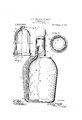
The invention consists of the parts and the construction and combination of parts as hereinafter more fully described and claimed, having reference to the accompanying drawings, in which Figure 1 is a side elevation of the cooling receptacle, partlyin section.
Fig. 2 is a similar view showing a modified form of same:
Fig. 3 is a cross section on line 33 of Fig. 2.
Referring to the drawings in detail, A indicates a glass bottle provided with an elongated neck 2, on the lower part of which is formed anexternal thread 3. Formed on the base portion of the bottle andextending outwardly is an annular flange 4, and adapted to surround or inclose the bottle and to be supported by the annular flange 4 is a porous covering 5 constructed of pottery or other like material.
Cooperating with the threaded section formed on the neck of the bottle, isan internally threaded sleeve 6, on the lower end of which is formed a flange 7 which is adapted to engage the upper end of the porous member 5 to secure it withrelation to the base flange 4 and also to form an ornamental top covering for the same. The bottle may otherwisc be provided with a stopper 8 and may be used for any purpose desired.
In operation, it is possible to fill the bottle with mil or any other medium it is de between the inner and outer members.
sired to keep cool. The stopper is then inserted to cover the contents and the outer covering 5 is saturated with water either by dlppmg the whole bottle or pouring the liquid thereon. The bottle may then be set in the atmosphere, preferably in a drafty place. This causes an evaporation of the water contained in the porous member and in this manner removes the heat from the inner receptacle, thus keeping the contents cool for a considerable period of time.
The particular object of this invention is to provide a structure of the character shown which may be easily taken apart and cleaned from time to time. This is accomplished by removing the screw cap 7 to permit the outer porous covering to be lifted away from the bottle. The bottle may then be washed or cleansed in any suitable manner and as the outer covering is temporarily removed, it is possible to view the interior surface. to positively determine that it is thoroughly cleaned. The outer porous cov-' ering may then be replaced and secured in position by the cap 7 and is then again ready for use.
The old-time porous, earthen ,jars commonly known as ollas are to a certain extent practically limited in their use to water.
bottles, as any other substance placed therein has a tendency to enter the interstices of the material, thus making it impossible to thoroughly clean same. In the present instance such objections are entirely obviated as the material to be cooled is placed within the glass receptacle A and can, therefore. not enter the pores of the exterior earthenware jacket or foul it in any way.
By referring to Figs. 2 and 3 another form of the device is shown. In this in stance a bell-shaped closure or member B, of glass or other suitable material, is prowith a porous medium 5*, as previously de scribed, which is secured by means 'of the screwcap 10. The inner surface of the earthenware jacket is preferably ribbed, as shown at 11, to provide an annular ace space may be filled with water from time to time which is gradually permitted to evaporate, as previously described. I
' A suitable pan-shaped base member 12, having .a raised bottom section 13, is referably provided in connection with the" 11-.
vided. This is also surrounded 0r jacketed his" 05 shaped closure here shown. The raised base section 13 formed rmits a free circulation of air around the ottle 14 or other object placed within the receptacle and the pan proper acts as a receiver for any moisture or condensation which might collect on the exterior surface of the porous jacket.
The form of the device shown in Figs. 2 and 3 is particularly adapted for cooling pur oses Where it is desired to cool foodstu s which cannot readily be poured into a receptacle of theform shown in Fig. 1, and it may be otherwise commended as it is only necessary to lift the bell from the pan to insert or remove article:- therefrom.
A. chamber formed in the upper end of the bottle permits water to be poured in from time to time to fill the space between the jacket and the inner lining member B to replace losses caused by evaporation, and a rubber gasket 15 ma y, if found necessary, be inserted between the lower base llange 'l and the lower edge of the porous jacket.
The materials and finish ofthc several parts of the receptacle may be such as the experience and judgment of the manufacturer may dictate.
We wish it understood that various changes in form, proportions and minor details of construction may beresorted to within the scope of the appended claims and that we do not wish to limit ourselves to the specific design and construction hcre shown.
Having thus described our invention. what we claim and desire to secure by Letters Patent is- 1. In a cooling device, an inclosure having a rigid neck-like part projecting upwardly from the body thereof and an annular flange on said body at the bottom, a rigid porous mcmbcrsurroundingsaid inclosure and seated on said flange, the upper end of said porous member being extended inwardly to and terminating at points adjacent the base of the neck-like part, said neck-like art having a portion of uniform diameter w ich is threaded and extends above said inwardly extending upper QDll of the porous member, and a sleeve threaded over said neck-like part so as to be supported positively b and from the threads of said neck-like part and having an annular flange which engages-on said inwardly extending upper end of said porous member to rigidly clamp the latter between the inclosurc flange and the sleeve flange.
' tween the neck porous member. and a sleeve carried by the 2. In a cooling device, an inclosurc closed at its top, a porous member surronndin the inclosure and having interior longitudinal spaced ribs which engage the inclosurc to space the porous member therefrom, and a. neck formed on the center of the inclosure top and projecting above the latter and closed at its bottom by said top of the inclo' sure and having a lateral duct ccmmunicating with the space between the inclosurc and porous member for admitting water placed in the neck to said space.
3. In a cooling device. an inclosure having a closed top, a neck seated at its base on said closed top of the inclosure so as to have a bottom formed by said inclosurc top, and a porous member cncirclin the inclosure and extending adjacent to tie neck, said neck having a duct which leads from its interior through its exterior to direct water placed in the neck against said porous member.
4. In a cooling device, an inclosure having a closed top. a ncck seated at its base on said closed top of the a bottom formed by said inclosurc top, and a porous member encircling the inclosure and having a vertical upper terminal which is located opposite to the neck in spaced relation thereto. said neck having alatcral duct which leads from the neck interior through the exterior thereof and into said space heaud the terminal of the neck and having a base flange which extends across the space between the porous member and neck.
5. In acoolin; device. an interior inclosure closed at its top, a porous member surrounding said inclosure, a neck on said inclosure extending up from the centc of the top thereof, said porous member surrounding the neck. and said neck having lateral ducts leading to the parts of the porous member which surround the ncck. and means extending over and scaling the joint between the neck and the parts of the porous member which surround the neck. I
In testimony whereof we have hereunto set our hands in the presence of a subscribing witness.
I JI LlUS F. MEDVECZKY.
FERDINAND MAYER. Witness:
. W. W. Haannr.
inclosurc so as to have I
Priority Applications (1)
| Application Number | Priority Date | Filing Date | Title |
|---|---|---|---|
| US10568416A US1237669A (en) | 1916-06-24 | 1916-06-24 | Cooling-receptacle. |
Applications Claiming Priority (1)
| Application Number | Priority Date | Filing Date | Title |
|---|---|---|---|
| US10568416A US1237669A (en) | 1916-06-24 | 1916-06-24 | Cooling-receptacle. |
Publications (1)
| Publication Number | Publication Date |
|---|---|
| US1237669A true US1237669A (en) | 1917-08-21 |
Family
ID=3305487
Family Applications (1)
| Application Number | Title | Priority Date | Filing Date |
|---|---|---|---|
| US10568416A Expired - Lifetime US1237669A (en) | 1916-06-24 | 1916-06-24 | Cooling-receptacle. |
Country Status (1)
| Country | Link |
|---|---|
| US (1) | US1237669A (en) |
-
1916
- 1916-06-24 US US10568416A patent/US1237669A/en not_active Expired - Lifetime
Similar Documents
| Publication | Publication Date | Title |
|---|---|---|
| US2767563A (en) | Heat transferring container support | |
| US2832493A (en) | Combination drinking glass and heat insulating coaster | |
| US1237669A (en) | Cooling-receptacle. | |
| US929389A (en) | Serving-cup for beverages. | |
| US2322665A (en) | Child's feeding dish | |
| US690457A (en) | Filter. | |
| US995415A (en) | Milk-pail. | |
| US1009406A (en) | Holder for iced beverages. | |
| US1625803A (en) | Water cooler and refrigerating apparatus | |
| US1652600A (en) | Bottled-beverage cooler | |
| US1744355A (en) | Shaving cup | |
| US1086425A (en) | Fluid-cooler. | |
| US1022565A (en) | Water-cooling ice-tray for refrigerators. | |
| US1054677A (en) | Water-cooler. | |
| US357122A (en) | John a | |
| US1038558A (en) | Tea and coffee pot and the like. | |
| US1568176A (en) | Milk can | |
| US678462A (en) | Coagulant-feeder. | |
| US992053A (en) | Coffee-pot. | |
| US2060420A (en) | Waste trap | |
| US1920398A (en) | Shaving brush | |
| US1004927A (en) | Water-cooler. | |
| US1431400A (en) | Milk cooler | |
| US1867868A (en) | Drinking water cooler | |
| US231367A (en) | Refrige rating-can |