US123763A - Improvement in riveting-machines - Google Patents
Improvement in riveting-machines Download PDFInfo
- Publication number
- US123763A US123763A US123763DA US123763A US 123763 A US123763 A US 123763A US 123763D A US123763D A US 123763DA US 123763 A US123763 A US 123763A
- Authority
- US
- United States
- Prior art keywords
- machines
- riveting
- improvement
- jaws
- rivets
- Prior art date
- Legal status (The legal status is an assumption and is not a legal conclusion. Google has not performed a legal analysis and makes no representation as to the accuracy of the status listed.)
- Expired - Lifetime
Links
- 230000003028 elevating effect Effects 0.000 description 2
- 235000021028 berry Nutrition 0.000 description 1
- 239000002184 metal Substances 0.000 description 1
Images
Classifications
-
- B—PERFORMING OPERATIONS; TRANSPORTING
- B25—HAND TOOLS; PORTABLE POWER-DRIVEN TOOLS; MANIPULATORS
- B25B—TOOLS OR BENCH DEVICES NOT OTHERWISE PROVIDED FOR, FOR FASTENING, CONNECTING, DISENGAGING OR HOLDING
- B25B5/00—Clamps
- B25B5/06—Arrangements for positively actuating jaws
- B25B5/08—Arrangements for positively actuating jaws using cams
Definitions
- This invention relates to riveting-machines adapted to receive and hold all of the rivets v required for the parts to be riveted together at a relative distance apart to correspond with the rivet-holes in the parts inwhich the rivets are inserted simultaneously by an elevating device, when all of the rivets are headed by a single continued operation.
- My present invention relates more particularly to the means for operating the clampingjaws which hold the rivets preparatory to inserting them in the rivet-holes; and consists in the combination and arrangement, with the socketed clamping-jaws arranged in a longitudinally-grooved mandrel, of two wedges operated by screws or equivalent means, and engaging with the movable clamping-jaw so asto' produce the same pressure on all parts of the same in clamping the rivets, as hereinafter more fully described.
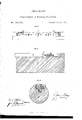
- Figure I is a plan view of a riveting-mandrel provided with my improvement;
- Fig. II a fragmentary sectional elevation on a larger scale of the same.
- Fig. III is a cross-section in line a: m, Fig. I.
- A is the body of the mandrel, consisting of a cylindricalbar of metal.
- a A are the clampingjaws arrangedin a longitudinal dovetail groove
- the jaw A is stationary, whilethe jaw A is movable toward and from the jaw A B is the rivet elevating-bar arranged below the jaws A A in a rectangular groove, as shown in the drawing. It is provided with pins b passing upward into the sockets c of the jaws A A said sockets being preferably angular in shape, as represented in to enable the jaws A A to' th drawing, so as clamp rivets of various sizes.
- the mechanism for elevating the bar B consists of two wedges arranged under the bar B at each end thereof, and connected by a connecting-rod to a lever, 0, supported in the block or frame O.
- the movable jaw A was operated by two screws arranged near its ends, which is objectionable, except in very short mandrels, on account of the said jaw being liable to spring or bend, which renders the same unable to securely hold the rivets near the center.
- D D are two wedges fitting in the dovetail groove of the mandrel between the latter and the movable jaw A They are of such length that when the jaws are closed their points nearly meet at the center.
- '11 d are two screws pinioned to the large end of each wedge so as to turn freely therein, and working in a bearing or nut, 01, formed with the block 0, or attached to the mandrel.
- ,e is a hand-wheel attached to each screw d for operating the same. Its circumference may be notched so that a wrench may be used for turning the screws.
- f are spiral springs arranged between the jaws A A so as to expand the jaws when the wedges D are loosened.
Landscapes
- Engineering & Computer Science (AREA)
- Mechanical Engineering (AREA)
- Forging (AREA)
Description
JAMES BERRYI Improvement in Riveting Machines.
Patented Feb. 20,1872.
UNITED STATES formed in the mandrel.
PATENT OFFICE.
JAMES BERRY, OF BUFFALO, NEW YORK, ASSIGNOR TO HIMSELF AND HENRY BERRY, OF SAME PLACE.
IMPROVEMENT IN RlVETlNG-MACHINES.
Specification forming part of Letters Patent No. 123,763, dated February 20, 1872.
r SPECIFICATION.
1, JAMES BERRY, of the city of Buffalo, in the county of Erie and State of New York, have invented certain Improvements in Rivetin g-Machines, of which the following is a specification:
This invention relates to riveting-machines adapted to receive and hold all of the rivets v required for the parts to be riveted together at a relative distance apart to correspond with the rivet-holes in the parts inwhich the rivets are inserted simultaneously by an elevating device, when all of the rivets are headed by a single continued operation.
. For a more particular description of .such
machines I refer to the specifications of my Letters Patent for improved Riveting-Mandrel, dated November 29, 1870, and numbered 109,57 5; and for improved Riveting-Machine dated August 22, 1871, and numbered 118,328.
My present invention relates more particularly to the means for operating the clampingjaws which hold the rivets preparatory to inserting them in the rivet-holes; and consists in the combination and arrangement, with the socketed clamping-jaws arranged in a longitudinally-grooved mandrel, of two wedges operated by screws or equivalent means, and engaging with the movable clamping-jaw so asto' produce the same pressure on all parts of the same in clamping the rivets, as hereinafter more fully described.
In the accompanying drawing, Figure I is a plan view of a riveting-mandrel provided with my improvement; Fig. II, a fragmentary sectional elevation on a larger scale of the same. Fig. IIIis a cross-section in line a: m, Fig. I.
Like letters designate like parts in each of the figures.
A is the body of the mandrel, consisting of a cylindricalbar of metal. A A are the clampingjaws arrangedin a longitudinal dovetail groove The jaw A is stationary, whilethe jaw A is movable toward and from the jaw A B is the rivet elevating-bar arranged below the jaws A A in a rectangular groove, as shown in the drawing. It is provided with pins b passing upward into the sockets c of the jaws A A said sockets being preferably angular in shape, as represented in to enable the jaws A A to' th drawing, so as clamp rivets of various sizes. The mechanism for elevating the bar B consists of two wedges arranged under the bar B at each end thereof, and connected by a connecting-rod to a lever, 0, supported in the block or frame O.
Heretofore, the movable jaw A was operated by two screws arranged near its ends, which is objectionable, except in very short mandrels, on account of the said jaw being liable to spring or bend, which renders the same unable to securely hold the rivets near the center. To obviate this difficulty I operate the movable jaws by the following means:
D D are two wedges fitting in the dovetail groove of the mandrel between the latter and the movable jaw A They are of such length that when the jaws are closed their points nearly meet at the center. '11 d are two screws pinioned to the large end of each wedge so as to turn freely therein, and working in a bearing or nut, 01, formed with the block 0, or attached to the mandrel. ,e is a hand-wheel attached to each screw d for operating the same. Its circumference may be notched so that a wrench may be used for turning the screws. f are spiral springs arranged between the jaws A A so as to expand the jaws when the wedges D are loosened.
It is evident that the wedges D produce the same pressure on the jaw A at all points,
whereby the same is enabled to clamp all of the rivets inserted in the sockets c, with equal security, which adds greatly to the efficiency of the machine.
I claim as my invent1on The combination and arrangement, with the mandrel A and socketed clamp-bars A A, of the wedges D D, and screws (1 cl, or equivalent means for operating the wedges, substantially as and for the purpose hereinbefore set forth.
Witnesses: JAMES BERRY.
EDWARD WILImLM, J omv J. BONNER.
Publications (1)
| Publication Number | Publication Date |
|---|---|
| US123763A true US123763A (en) | 1872-02-20 |
Family
ID=2193197
Family Applications (1)
| Application Number | Title | Priority Date | Filing Date |
|---|---|---|---|
| US123763D Expired - Lifetime US123763A (en) | Improvement in riveting-machines |
Country Status (1)
| Country | Link |
|---|---|
| US (1) | US123763A (en) |
-
0
- US US123763D patent/US123763A/en not_active Expired - Lifetime
Similar Documents
| Publication | Publication Date | Title |
|---|---|---|
| US123763A (en) | Improvement in riveting-machines | |
| US957560A (en) | Pliers or pipe-tongs. | |
| US553284A (en) | Frank a | |
| US373891A (en) | Charles hall | |
| US851794A (en) | Punch, pliers, &c. | |
| US109575A (en) | Improvement in riveting-mandrels | |
| US613535A (en) | Bench-vise | |
| US113656A (en) | William p | |
| US1349213A (en) | Pressure-bar | |
| US55199A (en) | Edwaed cook | |
| US115275A (en) | Improvement in vises | |
| US109913A (en) | Improvement in wrenches | |
| US120521A (en) | Improvement in machines for upsetting tires | |
| US1068671A (en) | Rivet-holding device. | |
| US110789A (en) | Improvement in wrenches | |
| US121078A (en) | Improvement in tire-machines | |
| US167922A (en) | Improvement in tire-upsetting machines | |
| US263991A (en) | syensson | |
| US835697A (en) | Link-forming machine. | |
| US118999A (en) | Improvement in vises | |
| US1191354A (en) | Handle for pneumatic tools. | |
| US513516A (en) | Mechanical hammer | |
| US88783A (en) | Improvement in bolt-machines | |
| US617834A (en) | Riveting-machine attachment | |
| US89631A (en) | Improved upsetting-machine |