US1237386A - Internal-combustion engine. - Google Patents
Internal-combustion engine. Download PDFInfo
- Publication number
- US1237386A US1237386A US75730813A US1913757308A US1237386A US 1237386 A US1237386 A US 1237386A US 75730813 A US75730813 A US 75730813A US 1913757308 A US1913757308 A US 1913757308A US 1237386 A US1237386 A US 1237386A
- Authority
- US
- United States
- Prior art keywords
- cylinders
- shaft
- crank
- crank case
- carried
- Prior art date
- Legal status (The legal status is an assumption and is not a legal conclusion. Google has not performed a legal analysis and makes no representation as to the accuracy of the status listed.)
- Expired - Lifetime
Links
- 238000002485 combustion reaction Methods 0.000 title description 18
- 239000003921 oil Substances 0.000 description 14
- 238000000926 separation method Methods 0.000 description 10
- 238000007689 inspection Methods 0.000 description 3
- 238000000034 method Methods 0.000 description 3
- 238000010276 construction Methods 0.000 description 2
- 230000001050 lubricating effect Effects 0.000 description 2
- 235000001674 Agaricus brunnescens Nutrition 0.000 description 1
- 241000482967 Diloba caeruleocephala Species 0.000 description 1
- 101100054070 Rattus norvegicus Andpro gene Proteins 0.000 description 1
- 101150057833 THEG gene Proteins 0.000 description 1
- 238000005266 casting Methods 0.000 description 1
- 238000004140 cleaning Methods 0.000 description 1
- 238000004891 communication Methods 0.000 description 1
- 230000003467 diminishing effect Effects 0.000 description 1
- 239000010687 lubricating oil Substances 0.000 description 1
- 238000005461 lubrication Methods 0.000 description 1
- 238000012423 maintenance Methods 0.000 description 1
- 239000011435 rock Substances 0.000 description 1
- XLYOFNOQVPJJNP-UHFFFAOYSA-N water Substances O XLYOFNOQVPJJNP-UHFFFAOYSA-N 0.000 description 1
Images


Classifications
-
- F—MECHANICAL ENGINEERING; LIGHTING; HEATING; WEAPONS; BLASTING
- F01—MACHINES OR ENGINES IN GENERAL; ENGINE PLANTS IN GENERAL; STEAM ENGINES
- F01L—CYCLICALLY OPERATING VALVES FOR MACHINES OR ENGINES
- F01L1/00—Valve-gear or valve arrangements, e.g. lift-valve gear
- F01L1/02—Valve drive
-
- Y—GENERAL TAGGING OF NEW TECHNOLOGICAL DEVELOPMENTS; GENERAL TAGGING OF CROSS-SECTIONAL TECHNOLOGIES SPANNING OVER SEVERAL SECTIONS OF THE IPC; TECHNICAL SUBJECTS COVERED BY FORMER USPC CROSS-REFERENCE ART COLLECTIONS [XRACs] AND DIGESTS
- Y10—TECHNICAL SUBJECTS COVERED BY FORMER USPC
- Y10S—TECHNICAL SUBJECTS COVERED BY FORMER USPC CROSS-REFERENCE ART COLLECTIONS [XRACs] AND DIGESTS
- Y10S123/00—Internal-combustion engines
- Y10S123/06—Detachable
Definitions
- This invention relates to internal combustion engines, and has for its general object the improvement of a device of this type in certain matters of detail connected with the design, assembling, and maintenance of the engine. More specifically the objects of the invention are the provision of a device of this character in which the cam shaft can be assembled independently of the rest of the engine, thereby permitting the'engine parts to be dismounted and repaired and inspected without clisarranging the cam shaft and its associated parts; the
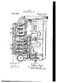
- Figure 1 is a forward end elevation of an engine constructed-in accordance with my invention:
- Fig. 2 is a transverse, cross-sectional view taken through the center of one of the valves;
- Fig. 3 is a longitudinal cross-sectional view taken upon the line 3-3 of Fig. 2 and looking in the direction of the arrows, a portion of the cam shaft housing being shown in side elevation;
- Fig. 4 is a per-spec tive view of the base frame showing the cam shaft housing in position thereon;
- Fig. 1 is a forward end elevation of an engine constructed-in accordance with my invention:
- Fig. 2 is a transverse, cross-sectional view taken through the center of one of the valves;
- Fig. 3 is a longitudinal cross-sectional view taken upon the line 3-3 of Fig. 2 and looking in the direction of the arrows, a portion of the cam shaft housing being shown in side elevation;
- Fig. 4 is a per-spec tive view of the base frame showing the cam shaft
- FIG. 5 is an end elevational view of the rearward end of the cam shaft housing showing the method of driving the lubricating oil pump;
- Fig. '6 is a detail view illustrating the method of supporting and operating the I governor;
- Fig. 7 is a transverse crosssectional view of an engine illustrating a sh htly modified form of cam shaft housing,
- the base consists of a one-piece ohlong casting having transverse walls 3, 3, 3, provided with semi-cylindrical journal halves 4, 4, 4', adapted for the reception of a crank shaft 5.
- three such walls are shown, one in the middle, and others spaced upon each side of the same a suflicient distance for the reception of two cranks, since a fourc linder engine is chosen for purposes of ilus'tration herein. It will be understoodthat the articular arrangement of these members. 18 entirely a matter of choice.
- the upper part 2 of the engine body comprises a cy11n der block 8 and a downwardly flaring portion 9, preferably integral therewith and adapted to be secured to the to of the engine base 1.
- the cylinder bloc .8 is made with a plurality of cylindrical recesses forming the cylinders, the same being here shown as vertical and directly in line with the crank shaft. These cylinders may have the usual water jackets 10, head 11,,and spark plugs 12.
- an extension 15 is provided formed with a plurality of vertical apertures 16, two apertures being allotted to each cylinder. These apertures communicate with chambers 17 and 18 formed in this extension cylinder, ahd connected with the exhaust and inlet manifolds respectively.
- each aperture 16 Cofiperating with each aperture 16 is a puppet valve 19 havaperture 16 and reoiprocable in a sleeve 21 mounted in the bottom wall of the chamber.
- the lateral extent of the extension 15 preferably causes it to come substantially flush with the sidewall of the engine base 1, and its vertical extent causes it to terminate in a fiat wall 22 intermediate between the ends of the cylinder bore.
- the ends of the stems 20 project a considerable distance beyond this wall 22, as illustrated in Figs. 2 and 3, and are provided adjacent to their ends with fixed collars 23 between whichand the wall 22 are interposed spiral springs 24 stantially upright wall as shown at 2.7 in
- Fig. :2 which may be braced from the eviinders by occasional ⁇ vchs 9S, and preferably has an elongated aperture. 29 immediately below t-h* wall '22 pcrmittin, 1 access to the valve stein for the purpose of inspection and repair.
- This aperture is preferably covered by a suitable platefifi 'hehl in )lace in any suitable manner as by the land clamp 31.
- the space provided inside the crank casin, by this peculiar construction is utilized for the. reception of the cam shaftin the manner now to be described.
- these rods are shown asprovided with mushroom heads 40,
- Each of the sleeves 37 is preferably formed with a-flanget1 ada )ted to engage the upper face of lthe thic ened port10n 36, and the sie'eves'lare secured in plae'e by means of yokes '42 bolted to the thickened Portion 36 and ngagin'gthe flanges.
- the sleeves 37, 37 are arranged, one in line nfitheach of the valve stems 20, and the upper end'o'f each of the rods 38 is provided with an adjustable extension 45 whereby the lift of the valve may be adjusted.
- the upper end of each of the slecvc's 37 is surmounted by an open cup 46, the bottom whereof is placed in constant communication with the interior of the housing 33 by means of a duct 47 formed in the sleeve 37.
- the sides of the housing 33 may. if desired, bi made integra but are preferably, as here shown, formed'with removable plates 48 permitting access to the interior for purposes of inspection, cleaning, and repair.
- crank shaft 5 is -mounted' in the journal halves 4 and secured therein by the yokes 55.
- One end-of thec'rank shii'jtfi'spro gear 57 carried by the lay shaft and serving to rotate the same at the proper speed.
- the gears 56 and 57 are shown as disposed at the opposite ends of the casingfrom the fly -w eel 58.4md
- the shaft 62 drives, through the agency of the belt pulley 64 and belt 65 a pulley 66 to which the radiator fan may be attached.
- the shaft 62 may also, if desired, drive a 'm eto (not shown) mounted upon the brac et 67, such arrangement being the alternative of that before sha spiral gears 57""and 59, and hence this resu cstod.
- the transverse relation of thei is -35 and 61 necessitates the use ofv quirement necessitates the use of spiral gears 56 and 60 also.
- a lay shaft housing consisting of atrough 33 having an upper part 33 secured to the same and completely inclosing the lay shaft 35.
- the upper part of the top 33 is formed with a thickened portion 36, as in the previous case, said thickened portion being a ertured for the reception of sleeves 37 as before.
- the combination with a split crank case having 0 its line of separation generally transverse to the ;cylinder axis and reciprocable valves carried :by the cylinders, the-cylinders being i carried by one portion of the crank case, of a lay shaft rotatably supported by the other nortion of 'th'ecrank case, cams carvices supported adjacent "to said cams and adapted to engage the stems of said valves.
- a split crank case having its line of separation generally transverse to the cylinder axis, and reciprocable valves carried by the cylinders, of brackets secured to the ortion ofsaid crank case farthest from said cylinders, a lay shaft j ournaled in said brackets at one side of said cylinders, and cams carriedv by said lay shaft and adapted to operate said valves.
- the combination with a split crank case having its line of separation generally transverse to the cylinder axis, and reciprocable valves carried by the cylinders, of a crank shaft journaled in the portion ofsaid crank case farthest from said cylinders, brackets carried by. the same portion of'the crank case as said crankshaft, :said brackets being disposed at one si e of said crank shalt and inside the limits of said case, a lay shaft journaled in said brackets, the length of said lay shaft being less than that of the case, driving connections between said shafts within the limits of said case, cams carried by said lay shaft, and operative connections between said cams and said valves;
Landscapes
- Engineering & Computer Science (AREA)
- Mechanical Engineering (AREA)
- General Engineering & Computer Science (AREA)
- Valve-Gear Or Valve Arrangements (AREA)
Description
B. READ. I INTERNAL COMBUSTION ENGINE.
APPLICATION FILED MAILZB. I913- Patented Aug; 21, 1917.
3 SHEETS-SHEET 1.
.Zzzz/Ezzzar.
B. HEAD. INTERNAL comausnow ENGINE.
APPLICATION FILED PM. 28 HHS. 1,237,386, Patented Aug. 21, 1917.
3 SHEETSSHEET 2 272255 5 235; 1222/2222 2272'. KX M vB. READ.
INTERNAL COMBUSTION ENGINE.
APPLICATION mzu MAR. 22. 1913. 1,237,386, PatentedAug. 21, 1917.
3 SHEETS SHEET 3.
4 XXMK Z/% (:6. 4201M BALFOUR READ, 0F MARION, INDIANA.
INTERNAL-COMBUSTION ENGINE.
Specification of Letters Patent.
' Patented Aug. 21 1917.
Application filed March 28, 1 918. Serial No. 757,308.
To all whom it may concern;
Be it known that I, BALroUn READ, a subject of the King of Great Britain, and a citizen of the Dominion of Canada, residing at Marion, in the county of Grant and State of Indiana, have invented a certain new and useful improvement in Internal-Combustion Engines, of which the following is a full, clear, and exact description, reference being had to the accompanying drawings.
This invention relates to internal combustion engines, and has for its general object the improvement of a device of this type in certain matters of detail connected with the design, assembling, and maintenance of the engine. More specifically the objects of the invention are the provision of a device of this character in which the cam shaft can be assembled independently of the rest of the engine, thereby permitting the'engine parts to be dismounted and repaired and inspected without clisarranging the cam shaft and its associated parts; the
provision of new and improved means for supporting the valve lifting devices and for lubricating the same; the provision of means for diminishing the noise produced by the operation of the-cams and valves; the-provision of*ne\v and improved means for permitting the inspection and adjustment of the valve operating devices; the provision of new and improved arrangement and mode of operating the water pump and magneto; while further objects and advantages of the invention will become apparent as the description proceeds.
Generally speaking my invention may be defined as consisting of the constructions and combinations recited in the claims here to annexed and illustrated in the drawings accompanying and forming a part of th1s application, wherein: Figure 1 is a forward end elevation of an engine constructed-in accordance with my invention: Fig. 2 is a transverse, cross-sectional view taken through the center of one of the valves; Fig. 3 is a longitudinal cross-sectional view taken upon the line 3-3 of Fig. 2 and looking in the direction of the arrows, a portion of the cam shaft housing being shown in side elevation; Fig. 4 is a per-spec tive view of the base frame showing the cam shaft housing in position thereon; Fig. 5 is an end elevational view of the rearward end of the cam shaft housing showing the method of driving the lubricating oil pump;.Fig. '6 is a detail view illustrating the method of supporting and operating the I governor; and Fig. 7 is a transverse crosssectional view of an engine illustrating a sh htly modified form of cam shaft housing,
escribing the parts by reference charm-- ters 1 represents the engine base and 2 represents generally the;upper part of the engine. The base consists of a one-piece ohlong casting having transverse walls 3, 3, 3, provided with semi-cylindrical journal halves 4, 4, 4', adapted for the reception of a crank shaft 5. In the present embodiment three such walls are shown, one in the middle, and others spaced upon each side of the same a suflicient distance for the reception of two cranks, since a fourc linder engine is chosen for purposes of ilus'tration herein. It will be understoodthat the articular arrangement of these members. 18 entirely a matter of choice. The upper part 2 of the engine body comprisesa cy11n der block 8 and a downwardly flaring portion 9, preferably integral therewith and adapted to be secured to the to of the engine base 1. The cylinder bloc .8 is made with a plurality of cylindrical recesses forming the cylinders, the same being here shown as vertical and directly in line with the crank shaft. These cylinders may have the usual water jackets 10, head 11,,and spark plugs 12. At one side of the cylinder bloclr. an extension 15 is provided formed with a plurality of vertical apertures 16, two apertures being allotted to each cylinder. These apertures communicate with chambers 17 and 18 formed in this extension cylinder, ahd connected with the exhaust and inlet manifolds respectively. Cofiperating with each aperture 16 is a puppet valve 19 havaperture 16 and reoiprocable in a sleeve 21 mounted in the bottom wall of the chamber. The lateral extent of the extension 15 preferably causes it to come substantially flush with the sidewall of the engine base 1, and its vertical extent causes it to terminate in a fiat wall 22 intermediate between the ends of the cylinder bore. The ends of the stems 20 project a considerable distance beyond this wall 22, as illustrated in Figs. 2 and 3, and are provided adjacent to their ends with fixed collars 23 between whichand the wall 22 are interposed spiral springs 24 stantially upright wall as shown at 2.7 in
Fig. :2, which may be braced from the eviinders by occasional \vchs 9S, and preferably has an elongated aperture. 29 immediately below t-h* wall '22 pcrmittin, 1 access to the valve stein for the purpose of inspection and repair. This aperture is preferably covered by a suitable platefifi 'hehl in )lace in any suitable manner as by the land clamp 31. The space provided inside the crank casin, by this peculiar construction is utilized for the. reception of the cam shaftin the manner now to be described.
Secured above the walls 3, 3, 3, as by means of the brackets 3:2. 32, is an elongated housing 33 provided with bearin 34, 34, in which is journalcd the lay sha t 35. The side of the housing 33 adjacent to the valve stems 20 is thickened as at 36, and this thickenedportion apertured for the reception-of bearing sleeves 37-, 37, in which are slidably mounted rods 38, each of which has its lower end formed to coiiperat-e with one of the cams 3!) carried by the shaft 35. In-
the-fprcscnt, embodiment, these rods are shown asprovided with mushroom heads 40,
although it is obvious that rollers 01' the like could be employed without invention. Each of the sleeves 37 is preferably formed with a-flanget1 ada )ted to engage the upper face of lthe thic ened port10n 36, and the sie'eves'lare secured in plae'e by means of yokes '42 bolted to the thickened Portion 36 and ngagin'gthe flanges.
The sleeves 37, 37 are arranged, one in line nfitheach of the valve stems 20, and the upper end'o'f each of the rods 38 is provided with an adjustable extension 45 whereby the lift of the valve may be adjusted. The upper end of each of the slecvc's 37 is surmounted by an open cup 46, the bottom whereof is placed in constant communication with the interior of the housing 33 by means of a duct 47 formed in the sleeve 37.
The sides of the housing 33 may. if desired, bi made integra but are preferably, as here shown, formed'with removable plates 48 permitting access to the interior for purposes of inspection, cleaning, and repair. v
-\.-;.'-t(u'h\tcd with the engine is the usual oil pump 30, here shown as of the rotary type and driven by the shaft 51 which in'turn is operated from the lay shaft 35 through the agency of spiral gears This oil pump is connected by means of the conduit 53 with the housing 33 sothat oil from the pump will be delivered under pressure into the interior of the housing, a small portion of it passing by wa v of the ducts (l7 to the cups 46 and overflowing into the interior of the crank cas and the remainder passing through suitable tubes 54 to the diflerent parts of the engine which require lubrication. The housing 33 thus takes the place of the usual header or manifold troinwhich the oil tubes start. The cams being entirely underneath the surface of the oil will he so thoroughly cushioned that the noise of their operation will be at a minimum, while the presence of oil in the cups 46 to a height above the lower ends of the valve stems will serve to cushion the ends of the rods against them, thus diminishin {hznoise at this the len ft 1 that of the crank casing permits t e housing together. with the lay shaft, cams, sleeves, cups, 'rods, etc., to be assembled in a convenient and etficient manner, and the upper part of the en 'ne applied to the base, part oint. Finally the housing 33 ein less thanafter the comp etion of this assembly, or removed therefrom without disturbing the lay shaft and its adjuncts.
The crank shaft 5 is -mounted' in the journal halves 4 and secured therein by the yokes 55. One end-of thec'rank shii'jtfi'spro gear 57 carried by the lay shaft and serving to rotate the same at the proper speed. In
the present embodiment, the gears 56 and 57 are shown as disposed at the opposite ends of the casingfrom the fly -w eel 58.4md
lubricating nmp 50, this arrangement being .E: chosen large y for purposes of design and i not necessarily to lowed. In' thge cmbodimcnq-Ihave shown. theg'ear-I57 as associated with'two gears', 59 and 60 ,-the' gear 59 being mounted it on a jockeyshaft. 61 transverse to the cran shaft 5, and-the gear 60 upon a secondjockeyshaft 62pm alleltherewith. The shaft 61 is here shown as connected to thewater pump 61 :indmay also drive a magneto 61" which is mounted upon the bracket 63. The shaft 62 drives, through the agency of the belt pulley 64 and belt 65 a pulley 66 to which the radiator fan may be attached. The shaft 62 may also, if desired, drive a 'm eto (not shown) mounted upon the brac et 67, such arrangement being the alternative of that before sha spiral gears 57""and 59, and hence this resu cstod.' The transverse relation of thei is -35 and 61 necessitates the use ofv quirement necessitates the use of spiral gears 56 and 60 also. Obviously the particular method of transmittingl power from the crank shaft tothe lay s aft is entirely optional with thcdesignce, the mode hereshown being merely a combination scheme for purposes of simplicity. Obviously spongers, chains, or any other suitable. ex- I I combination, with-a split crank case having modified formof engine base. In this view the walls 3 of the base are shown as projecting a considerable distance above the center of the crank shaft 5 necessitating the em loyanent of bearings of correspondin di ererit shape, the height of the upper portion of the crank casing being correspondinglyreduced as illustrated at 9. Mounted upon the upper edges of the walls 3 upon 1'] short brackets 32 is a lay shaft housing consisting of atrough 33 having an upper part 33 secured to the same and completely inclosing the lay shaft 35. The upper part of the top 33 is formed with a thickened portion 36, as in the previous case, said thickened portion being a ertured for the reception of sleeves 37 as before.
For overnin the speed of the engine, I i, referaily emp by the device illustrated in j igs. 3 and 6 which consists of a hollow a shaft 71 coaxial therewith andpro'vide inside the casing "with suitablefiy-ball governor mecha-,
- pear-shaped casing 70 having nism 72 as illustrated in Fig. 3; 1 The cas "ingis supported upon a pivot 73 transverse to the crank shaft 5 in suchmanner'that the end of the shaft 71 shall project over and pmllel to the fly-wheel, and the'shaft 71 is provided with a. friction wheel 74 adapted to he held against the periphery of the flywheel by means of 'a s ring 75 whereby the whole casing70 is roc ed. The movement of the tgovernor balls is transmitted by means 0 a finger 76and rock shaft 7 to an st' arm'78 exterior of the casing 70. A link 79 ";i ccmnects the end of this-arm to the handle gfl$0 of a suitable throttle .valve or damper "mounted in the inlet manifold 81, and in t 's wayjthe'operation of the engine is cony throttling the charge.
While I have necessarily described my in 'v ion in detail, I do not propose to be to such details, except as the same "Winay bepositively included in-the claims T4 6 hereto annexed or may be rendered necesfsary by the rior state of the art.
,Havm 1 t us described my invention, whatIcaimis:
1. In an internal combustion engine, the
its line of separation generally transverse to the cylinder. axis,cylinders carried by one portion of the crank case, and reciprocable valves .carried by the c linders, of a lay t'fshaft rotatably supports by the other porion of the crank case, and cams carried by said, lay shaftffor operatin Said Valves .2. In an internal combustion engine, the combination, with a split crank case having 0 its line of separation generally transverse to the ;cylinder axis and reciprocable valves carried :by the cylinders, the-cylinders being i carried by one portion of the crank case, of a lay shaft rotatably supported by the other nortion of 'th'ecrank case, cams carvices supported adjacent "to said cams and adapted to engage the stems of said valves.
3. In an internal combustion engine, the
combination, with. a split crank case having its line of separation generally transverse to the cylinder axis, and reciprocable valves carried by the cylinders, of brackets secured to the ortion ofsaid crank case farthest from said cylinders, a lay shaft j ournaled in said brackets at one side of said cylinders, and cams carriedv by said lay shaft and adapted to operate said valves.
4. In an internal combustion engine, the combination, with a split crank case having its line of separation generally transverse to the cylinder axis, and reciprocable valves carried by the cylinders, of a crank shaft journaled in the portion ofsaid crank case farthest from said cylinders, brackets carried by. the same portion of'the crank case as said crankshaft, :said brackets being disposed at one si e of said crank shalt and inside the limits of said case, a lay shaft journaled in said brackets, the length of said lay shaft being less than that of the case, driving connections between said shafts within the limits of said case, cams carried by said lay shaft, and operative connections between said cams and said valves;
5. In an internal combustion engine the combination, with a split crank case, and cylinders carried by one part of the same,
the plane of separation of said crankcase being generally transverse to the axis of the cylinders, of a crank shaft journaled in the part of said case farthest from said cylinders, reciprocable valves i'nounted at one- "side of said cylinders and substantially parthe plane of separation of said crank case being generally transverse to the axis of the cylinders, of a crank shaft journaled in the part of said case farthest from said cylin- Vders, reciprocable valves mounted at one side of said cylinders and substantially parallel therewith, a trough supported by the side of said crank case farthest from said cylinders, a lay shaft journaled in said trough, camscarried by said lay shaft Within said trough, and valve lifters carried by said trough and coiiperatin with said cams, each of said valve lifters being operassociated with one of said valves. 7
combination, with a split crank case, a crank an internal combustion engine, the H shaft journaled in one half of said crank case, and cylinders carried by the other half of the case, the plane of separation of said case being generally transverse to the axis of said cylinders, of reciprocable valves mounted at one side of said cylinders and substantially parallel therewith, the side of said crank case carrying said cylinders being laterally enlarged upon the side of said valves for the reception of valve operating means, a lay shaft rotatably supported by the side of said crank case farthest from said cylinders, cams carried by said lay shaft, and valve operating means supported upon the same side of said crank case as the lay' shaft and projecting into the enlarged portion of the other part of the crank case. i 8. In an internal combustion engine, the combination, with cylinders and reciprocable valves mounted'at one side of said cylinders and substantially parallel therewith, of a split crank case, one part of said crank case being connected with said cylinders and having a lateral enlargement upon the side adjacent said valve, a crank shaft journaled in the other half of said crank case, the plane of separation of said crank case halves being generally transverse to the axis of said cylinders, brackets carried by the half of said crank case farthest from said cylinders and projecting into the enlarged portion of the other crank case half, a lay shaft journaled in said brackets and substantially parallel with the crank shaft, sleeves supported by said brackets substantially in line with said valves, jump rods mounted in said sleeves and adapted to engage the stems of said valves, and cams carried by said lay shaft and adapted to reciprocate said jump rods.
9. In an internal combustion engine, the
combination, with cylinders and recipro-.
cable valves mounted. at one side of said cylinders and substantially parallel therewith, of a split crank case, one part of said crank case being connected with said cylinders, and the plane of separation of said crank case halves being generally transverse to the axis of said'c linders, a crank shaft journaled in the ot er half of said crank case, brackets carried by the half of said crank case farthest from said cylinders and projecting into the other crank case half, an oil trough carried by said brackets, a lay shaft journaled in said trough and substantially parallel with the crank shaft, valve lifting devices carried by said trough in contact with the oil therein, and cams carried by said lay shaft and adapted to operate said valve lifting devices.
10. In an internal combustion engine, the
combination, with cylinders and reci rocable valves for said cylinders, of a lay s aft at one side of said cylinders, a trough surrounding said lay shaft, cams carried by said shaft within said trough, longitudinally reciprocable valve operating members projecting into said trough into proximity to said cams, and means for maintainin said trough filled with oil whereby sai cams and a portion of said valve operatin mechanism will be continually submerge 11. In an internal combustion engine, the combination, with cylinders and reciprocable valves for said cylinders, of a split crank case, one part of said case carrying the cylinders and the plane of separation of the case-parts being generally transverse to the axes of the cylinders, of a frame secured to the part of the crank case farthest from said cylinders, bearings carried by said frame, a lay shaft journaled in said bearings, cams carried by said shaft, and valve operating members carried by said frame and engaging said cams, said valve operating members being entirely independent of said case parts.
12. In an internal combustion engine, the combination, with cylinders and reciprocable valves for said cylinders, of a lay shaft at one side of said cylinders, a trough surrounding said lay shaft, cams carried by said shaft within said trough, longitudi-, nally reciprocable valve operating members projecting into said trough into proximity to said cams, an oilpump, and connections between the oil' pump and said trough whereby said trough is kept plentifully supplied With oil and said lay shaft and valve operating means continually submerged.
13. In an internal combustion engine, the combination, with cylinders and recipro cable valves for said cylinders, of a lay shaft at one side of said cylinders, a housing inclosing said lay shaft, cams carried by said shaft, valve operating members projecting into said housing and extending into proximity to said cams, an oil pump, and, connections between said oil pump and the interior of said housing, said housing being formed with relief openings adjacent to said valve operating members for the overflow of oil therefrom.
In testimony whereof, I hereunto aflix my signature in the p esencr of two witnesses.
i iLFoUR READ.
Witnesses ETHEL READ, FERNE ANDERSON.
its
Priority Applications (1)
| Application Number | Priority Date | Filing Date | Title |
|---|---|---|---|
| US75730813A US1237386A (en) | 1913-03-28 | 1913-03-28 | Internal-combustion engine. |
Applications Claiming Priority (1)
| Application Number | Priority Date | Filing Date | Title |
|---|---|---|---|
| US75730813A US1237386A (en) | 1913-03-28 | 1913-03-28 | Internal-combustion engine. |
Publications (1)
| Publication Number | Publication Date |
|---|---|
| US1237386A true US1237386A (en) | 1917-08-21 |
Family
ID=3305205
Family Applications (1)
| Application Number | Title | Priority Date | Filing Date |
|---|---|---|---|
| US75730813A Expired - Lifetime US1237386A (en) | 1913-03-28 | 1913-03-28 | Internal-combustion engine. |
Country Status (1)
| Country | Link |
|---|---|
| US (1) | US1237386A (en) |
-
1913
- 1913-03-28 US US75730813A patent/US1237386A/en not_active Expired - Lifetime
Similar Documents
| Publication | Publication Date | Title |
|---|---|---|
| US1617986A (en) | Internal-combustion engine | |
| US1410019A (en) | Internal-combustion engine | |
| US1237386A (en) | Internal-combustion engine. | |
| JPH02502663A (en) | Internal combustion engine with cross-flow cylinder head, especially with air-cooled single cylinder head for motorcycle internal combustion engine | |
| US2607328A (en) | Diesel motor | |
| US2969781A (en) | Internal combustion engine | |
| US2311146A (en) | Internal combustion engine for aircraft | |
| US1293712A (en) | Hydrocarbon-motor. | |
| US1916522A (en) | V-8 engine | |
| US1795865A (en) | Hydraulic slack adjuster | |
| US1443719A (en) | Internal-combustion engine | |
| US2093495A (en) | Engine crankshaft linkage | |
| US1639333A (en) | Explosive engine | |
| US1475965A (en) | Valve operating mechanism for internal combustion e | |
| US1219781A (en) | Internal-combustion engine. | |
| US1271354A (en) | Valve mechanism for internal-combustion engines. | |
| US1443856A (en) | Internal-combustion engine | |
| US1816406A (en) | Aeroplane engine | |
| US1274813A (en) | Internal-combustion engine. | |
| US1361619A (en) | Internal-combustion engine | |
| US2048018A (en) | Engine | |
| US1468516A (en) | Explosive engine | |
| US1533004A (en) | Multiple-cylinder combustion motor | |
| US1086180A (en) | Internal-combustion engine. | |
| US1277742A (en) | Internal-combustion engine. |