US1237378A - Excelsior-machine. - Google Patents
Excelsior-machine. Download PDFInfo
- Publication number
- US1237378A US1237378A US1614015A US1614015A US1237378A US 1237378 A US1237378 A US 1237378A US 1614015 A US1614015 A US 1614015A US 1614015 A US1614015 A US 1614015A US 1237378 A US1237378 A US 1237378A
- Authority
- US
- United States
- Prior art keywords
- knife
- shaft
- blocks
- plane
- cam
- Prior art date
- Legal status (The legal status is an assumption and is not a legal conclusion. Google has not performed a legal analysis and makes no representation as to the accuracy of the status listed.)
- Expired - Lifetime
Links
- OKTJSMMVPCPJKN-UHFFFAOYSA-N Carbon Chemical compound [C] OKTJSMMVPCPJKN-UHFFFAOYSA-N 0.000 description 4
- 102100027069 Odontogenic ameloblast-associated protein Human genes 0.000 description 1
- 101710091533 Odontogenic ameloblast-associated protein Proteins 0.000 description 1
- 229910000746 Structural steel Inorganic materials 0.000 description 1
- 241000718541 Tetragastris balsamifera Species 0.000 description 1
- 230000004048 modification Effects 0.000 description 1
- 238000012986 modification Methods 0.000 description 1
- 230000008707 rearrangement Effects 0.000 description 1
- 239000002023 wood Substances 0.000 description 1
Images

Classifications
-
- B—PERFORMING OPERATIONS; TRANSPORTING
- B27—WORKING OR PRESERVING WOOD OR SIMILAR MATERIAL; NAILING OR STAPLING MACHINES IN GENERAL
- B27L—REMOVING BARK OR VESTIGES OF BRANCHES; SPLITTING WOOD; MANUFACTURE OF VENEER, WOODEN STICKS, WOOD SHAVINGS, WOOD FIBRES OR WOOD POWDER
- B27L11/00—Manufacture of wood shavings, chips, powder, or the like; Tools therefor
- B27L11/02—Manufacture of wood shavings, chips, powder, or the like; Tools therefor of wood shavings or the like
- B27L11/04—Manufacture of wood shavings, chips, powder, or the like; Tools therefor of wood shavings or the like of wood wool
Landscapes
- Engineering & Computer Science (AREA)
- Life Sciences & Earth Sciences (AREA)
- Manufacturing & Machinery (AREA)
- Mechanical Engineering (AREA)
- Wood Science & Technology (AREA)
- Forests & Forestry (AREA)
- Manufacturing And Processing Devices For Dough (AREA)
Description
Y F. H'. PHILLIPS.
EXCELSIOR MACHINE.
APPLICATION man mm2. 1915.
1,237,378. Panmug. 21,1917.
2 sHEETs-sHE'Er 1.
vwewtoz @WMM/112.00%
F. H. PHILLIPS.
EXCELSIOR MAcHmE.
.APPLICATION FILED'MAR. 22 1915. l
Patented Aug. 21, `1917.
2 SHEETS-SHEET 2.
WIM/masas f UNITED Ennivx n; rnILLrrsgor cnr:vfEnnNn,1rEivnEs'sEE,y AssreNoE ro GEORGE n; ANDREWS. o
T all 'whom t may concern.'
- Be a known that I, rami-I. fiamme,
a ycitizen of the United?States,y residing'at fOleveland,1 in Ythecounty ofBradley, State of Tennessee, have invented certain new andinseful Improvementsy in Excelsior-k `Machinesiof which the, following .isa speci- `cation.
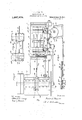
\ provision :of a machinewin `Whichthe knife -Infthe` accompanying. drawings j Flgurel 1s; a side elevation of the magk My invention relates to'v :an excelsiormachiney andi has/as its principal "object @the is clear `of the log operated upon during the f return Lor idle stroke of thennachine. y
\ .'.Afurther lobject `of"my-w'invention resides in the particular arrangement .and combination of.` parts hereinafter described chine. v n
Fig.\ v24 vis top plan view ofthe device shown in Fig. `1. f
Fig. 5 bis a detail elevational view show- `ing thecamand arinfor operating the feed levers'. y y n Fig. Gis a detail 'y ofthe feed shaft and levers.
Eig. 7 is a. detail,Showingfhowthe feed can he thrown ont of operation.
Throughout `the separate views thesame part 1s designated by` .the same' reference character. o f
Referring more 'particularly tothe draiv-` ings, 1. is a bed `on which is journaled a shaft 2 which maybe "driven in 'any con-` venient manner, hut which isk shovvnnas drivenfjbv a pulleyl, afloose pulley l lbeing provided for convenience. On "the, end` yof theshaft-`2fopposite thepulley 3 is karcran'k diskl :carrying apin @which is pivoted to end ofwthelpitmanbeingpivotedfto a pin 8 .Which-.isffixed toxthe cuttingihead 9L `It c will be 'seen 'fthattheheadf 9 ris arranged to reciprocate 7on rods such ras'g'10 which arey fastened atene side `offthefloed 11 :to standairdsrforhousings .suchas 11, the housings rheingftinedfto the bed l. MItvvill, moreover,
appear .from Fig.y thatthe cutting headlS carries a; knife 12.701 a 'kind in ordinary use .siieciaannn of Letters rate-nt. Patented Aug 21, 1917s f Application ilcdrMarch 22, 1915.. `Serial No. 16,140.
shavings may escape tothe outsidel of the'` head. vIt Will `he understood that the log or block to 'he operated on is introduced into .the Amachine lbetween the standards 11 fromfthe side` opposite the knife 12 and I provide an angle iron 14 for supporting the i .itis beingplaced 4in the machine I provide short plates 15-15 which kare carried (by the head-9 on vthe inner side thereof.
Novv I provide an arrangement not only `forpaving the ,log a graduall feed toward =theknife,bnt also for moving the log away .from the knife on the back stroke of the knife.; With these objects in view I provide a table `comprising horizontal plates 16?l and liunited by rods such as 17, Which are `let into sockets or recesses in the upper faces of` blocks such as y18, plate 16a being looseon the rods 17 and plate 16 ,being fixed to the base 1 and which extend at :rightl angles tothe motion of the knife 12.
Nowthe guides 19 are broken away at `one `point so `asl to receive reciprocating blocks such: as 20, each of which is provided With a pin k35,the `blocks 20 being arranged to reciprocate .parallel to the knife 12 and the blocks 18 4being provided with slots 21 `oblique tothe .direction of reciprocation of knife.` Itvvill be seen that `the blocks 20 are `connected together by link 22 so as to -ymove together and the .blocks are operated i p by'falink Which connects toa link 24,1the one end` ofrlthe link orpitnian 7, the other` ico lastwlink `being operated by levers such as 125 which carry rollers 26 in operative 'en-4 gagement with the vcam 27 iXed onthe shaft n 2.`*As shovvny invFig.` 3 I providealsoa spring 28 which is connected .by an arm 29 to the' rlink22, the spring 28 serving to pull Athe ibloclr 20 in` the same .direction las one of the levers 25;k Itwill be evident that, if n y desired, ,fone of the levers `25 androllers 26 kmay he omitted.` Novvthe plates 16a and `116l carry upright iianges or standards 80a and 304 respectively and at the ends near n di) clamped tothe rods 17 On their under-side `theplate's 16u and 16 restlon, but are not directly Aconnected with, the blocks 18 which {have-doveftailed engagement With guides 19 proper'direction and, moreover, the log can be moved back away from the knife by givn ing `a reciprocating fmotion' to the plates 16 and 1.6.' The plates are operated bythe blocks 2O previously'mentioned'through instrumentality of pins `35 previouslv mentioned in the blocks 20, the blocks 20 being moved bythe cam 27.
Now, as previously mentioned, the plate laisfslidableon the rod 17 andthis is for the purpose of-'permitting the standard 30a, carried bythe plate 16a, to be moved transversely ofthe carrier to permit a blockof wood to beinserted betweenthe rollers and I provide a weight 86y which connects with the movable. standard a carrying the l roller 32 through link37 and 88 in such manner that the roller is normally thrown into engagement with theblocln In order to operate the rollers 82 and 83 I provide gears such as 38 at the Vupper ends of the rollers-which connect with worms 39 carried by a shaft 40 suitably journaled at the top of4 thestandards 30. Means for properlyy rotating the shaft 40 in order tofeed the block toward the knife is shown indetail inFigs. 5,6 and 7 and appearsalsolon Figs. 1 and 2. Such'operating means comprises a' cam 41 on the shaft 2 immediately adjacent the crank disk 5, In operative contactfwith the'werking face of the cam 41 is a roller 42 which is pivoted on a lever arm 48, the nini 43 being' arranged to work in a lplane at right angles tothe plane of rotation ofthe cam 41 on shaft 2. yThe arm 43 is fiXed'to a shaft 44 the other end of Awhich carries an arm 45 which serves to operate the shaft 40 by means "of a p'awl 'and ratchet motion comprising an arm-46 loose on the shaft 40^which connectsiwith the arm 45 by means of a link 47. Carried on the arm 46 is a' pawl 48 which operates yin conjunction witha ratchet wheel 49` in the :usual manner. `I` provide,v however, means whereby the pawl 48 may be thrown out of operation which comprises a pin 50 pivoted to the arm'46 which extends into' a recess 'in' the `projection 51' on the p'awl member .48; I provide alsov a springe` 52 in the `said )recess and :it will be seen that the lpivot points of the members-48 and 50 arel so arranged that the spring normallyvtends to throw the pawl into engagement withy the -euttingstrokeia y,
\ `It"will beunderstood that the rmachine wheel 49. However, if the members 48 and 5()y are pushed to one side s o that the eXtension 51 is no longer in alineinentwith" the pin 5,() .-then the spring serves to hold the pawl 48 away from the ratchet. It will be seenmoreover, that Iprovide a spring 52 which serves to operate the arm 45 in a direction contraryA to the cam 41. From the foregoing it will be understood that the revolution of the cam 41 serves to revolve the rollers 32 and 83 so as to f-eed toward the block or log against the knife 12.i
-As previously stated, moreover, i the standard 30a 'and plate la'which are associatedwith the roller are'movable on the Irods 17 bntthat the shaft l40 is fixed with respect to the standard 80, so far as longitudinal r`movement is concerned. Consequently I maketheworm 39 which is associated with lthefeed roller 82 slidable longitudinally of the shaft 40, the two'fbeing connected bya key or spline, and holdthe worm 39 in properfposition relatively yto the corresponding wheel 88 by means of a finger 58 whichfits in agroove formed by 4a col'- lar fixed to the wo=r1n39 and which is also fastened to the corresponding standard.
Considering` now the operation of the machine asa whole,f:it will be understood that the cutting head 9 which carries the knife 12 is reciprocated by the `crank-disk 5 in a manner previously described. As they knife moves toward the right in Fig. 1 the blocks 20 `are lplaced in such position by the cam 27 and spring 28 and associated mechanism that the plates 164 are advanced toward the tknife and the vknife cuts a series ofshavings from the block or log. As the knifemakes yits return'stroke the blocks '2O are moved so as to throw the plates 16 back mvay-'froni the knife, so thatthe knife makes its return stroke entirelyvfree from` the log.; `I find that this feature of returning the knife free of they block not only' greatly prolonge the life of the knife, but also eliminates about ninety per centi: ofthe trouble which has heretofore I'been lencountered with the reciprocating type of eXcelsior machines. At the same time that the knife makes its return stroke and the `plates'lG/are moved away from thel knife, the .cam 41 operates the arm `45 so v"as yto draw. thesame into its normal position; -I-Iowever, as the plates are mov ing rapidly at .this time no operation of the l feed rollers 32 and 33 occurs :until the plates 16 are mov'edto-ward the knife again. A s soon as this happens the arm 46 is moved so as to turn-the ratchet:\vheel`-49 whereuponthe cam: 41 releases the arm 45 andthe springs throw the same forward again., Thusfthe log is pressed forward at the time the ,plates 16 are moved forward land a fresh 'f cutting surface is presented to the knife for the next are `means for reciprocating.
specifically described herein embodies the preferred form of my invention, but there modifications and thereof that may be made as will be apparent to tlioseskilled in the mechanical art, and
I contemplate as being within the spirit ofy riei, an arm mounted to move in a plane at right angles to the plane of rotation of said cam, a shaft xed to said arm, a second arm mounted to move parallel to first mentioned arm fixed to the other end of said shaft, and a link connecting` said last mentioned arm to said pawl and ratchet mechanism.
2.; In an eXcelsi'or machine in combination, a main driven shaft, a knife, connections between said shaft and knife for reciprocating ythe knife in a plane at right angles to the' shaft, a carrier for blocks mounted toy move in a to the plane of the knife, tions between said blocks and said vcarrier whereby the carrier is moved ,toward and plane parallel away from the plane of the knife at each` cutting and return stroke thereof, a cam carried by said shaft for .operating said blocks, and means for operating said blocks from said cam.
3. In an excelsior machine in combina-` tion, a main driven shaft, a knife, connec-` tions between said shaft and knife for recip- Copies of this patent maybe obtained for ve cents each, by addressing the rearrangements said independent feeding means comprisinga cam mounted on said shaft, a pawl and ratchet mechanism mounted on said car-i a block to `be operated on, said carrier being mountedv to'inove to-` ward and away from kthe plane of the knife,`
operative connecrocating the knife in a plane at right angles to the shaft, a carrier for a block to be operated on, said carrier being mounted to move toward and away from the plane of the knife, blocks mounted to move in a plane kparallel to the plane of the knife, operative` connections between said blocks and said rcarrier whereby the carrier is moved toward and away from the plane of the knife at each cutting and return stroke thereof, `a cam carried by said shaft for operating said blocks, means for operating said blocks from` said cam, feeding means mounted on said carrier for feeding the blocks toward the plane of the knife, a second cam on said shaft, and connections between said cam .and said feeding means, said feeding means remaining stationary as the carrier is drawn away from the plane of the knife and feedsecond mentioned cam` and the rforward movement of the carrier as the carrier moves toward the plane of the knife.
4. In an eXcelsior machine in combination,a main driven shaft, a knife, connec- -tions between said shaft and knife for reciprocating the knife'iii a plane at right angles to the shaft, a carrier for a block to be operated on, said carrier being mounted to move toward and away from the plane of theknife, blocks mounted to move in a plane carrier wherebyv the carrier is moved toward and away from the plane of the knife i at each cutting and return stroke thereof, cam carried by said shaft for operating said blocks, and means for operating said blocks from said cam, said connections oom- `prising pins on one part, and slots in the other part engaging said pins and set at an angle to the movement of the carrier.
In testimony whereof Il afi'iX my signature` in presence of two witnesses.
FRANK H. PHILLIPS.
Commissioner of Patents j n Washington, D. C.
fing forward under combined action of said n parallel to the plane of the knife, operative` v f `connections between said blocks and said
Priority Applications (1)
| Application Number | Priority Date | Filing Date | Title |
|---|---|---|---|
| US1614015A US1237378A (en) | 1915-03-22 | 1915-03-22 | Excelsior-machine. |
Applications Claiming Priority (1)
| Application Number | Priority Date | Filing Date | Title |
|---|---|---|---|
| US1614015A US1237378A (en) | 1915-03-22 | 1915-03-22 | Excelsior-machine. |
Publications (1)
| Publication Number | Publication Date |
|---|---|
| US1237378A true US1237378A (en) | 1917-08-21 |
Family
ID=3305197
Family Applications (1)
| Application Number | Title | Priority Date | Filing Date |
|---|---|---|---|
| US1614015A Expired - Lifetime US1237378A (en) | 1915-03-22 | 1915-03-22 | Excelsior-machine. |
Country Status (1)
| Country | Link |
|---|---|
| US (1) | US1237378A (en) |
-
1915
- 1915-03-22 US US1614015A patent/US1237378A/en not_active Expired - Lifetime
Similar Documents
| Publication | Publication Date | Title |
|---|---|---|
| US1237378A (en) | Excelsior-machine. | |
| US432477A (en) | casey | |
| US410403A (en) | Boabds feom logs | |
| US497980A (en) | Sawing-machine | |
| US289817A (en) | Boring-machine | |
| US358045A (en) | Machine for dressing shingles | |
| US132911A (en) | Improvement in apparatus for cutting disks of sugar into cubes | |
| US1288083A (en) | Lumber-marking device. | |
| US680937A (en) | Power-shears. | |
| US316073A (en) | Leather-cutting press | |
| US480735A (en) | muller | |
| US152473A (en) | Improvement in mortising-machines | |
| US393495A (en) | Cloth cutting machine | |
| US818142A (en) | Log-turner. | |
| US411401A (en) | Card-stamping machine for jacquard machines | |
| US172325A (en) | Improvement in machines for planing stereotype-plates | |
| US670549A (en) | Stamp-mill attachment. | |
| US9379A (en) | Peters | |
| US473432A (en) | Half to william m | |
| US58722A (en) | Improvement in wood-scraping machines | |
| US379451A (en) | crane | |
| US742439A (en) | Shingle-machine. | |
| US775916A (en) | Crosscut table-saw. | |
| US1732066A (en) | Cutting press | |
| US292361A (en) | Maoeine foe deessim stone |