US1237366A - Apparatus for grinding optical lenses. - Google Patents
Apparatus for grinding optical lenses. Download PDFInfo
- Publication number
- US1237366A US1237366A US87529914A US1914875299A US1237366A US 1237366 A US1237366 A US 1237366A US 87529914 A US87529914 A US 87529914A US 1914875299 A US1914875299 A US 1914875299A US 1237366 A US1237366 A US 1237366A
- Authority
- US
- United States
- Prior art keywords
- frame
- grinding
- optical lenses
- clip
- clutch
- Prior art date
- Legal status (The legal status is an assumption and is not a legal conclusion. Google has not performed a legal analysis and makes no representation as to the accuracy of the status listed.)
- Expired - Lifetime
Links
- 230000003287 optical effect Effects 0.000 title description 7
- 239000000463 material Substances 0.000 description 3
- 239000011435 rock Substances 0.000 description 2
- 101100075747 Drosophila melanogaster Lztr1 gene Proteins 0.000 description 1
- ONIBWKKTOPOVIA-BYPYZUCNSA-N L-Proline Chemical compound OC(=O)[C@@H]1CCCN1 ONIBWKKTOPOVIA-BYPYZUCNSA-N 0.000 description 1
- ATJFFYVFTNAWJD-UHFFFAOYSA-N Tin Chemical compound [Sn] ATJFFYVFTNAWJD-UHFFFAOYSA-N 0.000 description 1
- 238000007493 shaping process Methods 0.000 description 1
Images
Classifications
-
- B—PERFORMING OPERATIONS; TRANSPORTING
- B24—GRINDING; POLISHING
- B24B—MACHINES, DEVICES, OR PROCESSES FOR GRINDING OR POLISHING; DRESSING OR CONDITIONING OF ABRADING SURFACES; FEEDING OF GRINDING, POLISHING, OR LAPPING AGENTS
- B24B9/00—Machines or devices designed for grinding edges or bevels on work or for removing burrs; Accessories therefor
- B24B9/02—Machines or devices designed for grinding edges or bevels on work or for removing burrs; Accessories therefor characterised by a special design with respect to properties of materials specific to articles to be ground
- B24B9/06—Machines or devices designed for grinding edges or bevels on work or for removing burrs; Accessories therefor characterised by a special design with respect to properties of materials specific to articles to be ground of non-metallic inorganic material, e.g. stone, ceramics, porcelain
- B24B9/08—Machines or devices designed for grinding edges or bevels on work or for removing burrs; Accessories therefor characterised by a special design with respect to properties of materials specific to articles to be ground of non-metallic inorganic material, e.g. stone, ceramics, porcelain of glass
- B24B9/14—Machines or devices designed for grinding edges or bevels on work or for removing burrs; Accessories therefor characterised by a special design with respect to properties of materials specific to articles to be ground of non-metallic inorganic material, e.g. stone, ceramics, porcelain of glass of optical work, e.g. lenses, prisms
Definitions
- Myiin'vention' relates' more particularly to 0 Van attachment suitable to be mounted on any machine such as in ordinary use for grindin'g'therinis of optica] lenses.
- Fig. 2 is', ⁇ a section of the saine cut through at'theline A, A, on Fig. 1.
- Figa 3 is-a transverse section broken away, illustratingv 'the rocking frame and gear.
- Figs. 4 and 5 are fragmentary transverse sectional views of details.
- Fig. 11 the grinding wheel 1 is shown carriedby the power shaft 3, which is journaied in the main frame 2.
- 'ihe power shaft carries at one en d the power pulley 4 and the other end is operatively connected, and gives motion to the' flexible driving ',sliaft-s 5 through the chain and spur geur shown or.
- the flexible driving shafts 5 are shown as :journaled in the rocking frame (i.
- the 'latter is carried by the shaft 7 as shown in Figs. '2 and 3, and is provided with the Vsprin,f ,rs 8, H, which are attached at the other 'end t-o the maiwfiana: 9 as .shown on Fig. l.
- a protractor 9. is carried by the rocking' frame (i, as shown in the different ii ures, and hears on its face a graduated sea eby which the angle at which the lens carried by' the clutch shall be presented to the'grinding ..60 face may be determined when the.spfring-l clip 10, .shown in the diiferentiiguress L' clamped in operative. position.
- VThe clip 10 Y' is adjustably inountedon the, protraetor 9' ,y
- the jaws of thc spring clip 10 are in'a'in'- tained in operativel position by the' Spring' 20, lshown in Fig. l, which spreads the han'- dles 1U and 10" and contracts the iaws; a pattern 1G. aLSo shown in said ligureheid with the material in the clutch ofthe jaws,-
- 'llie clip is then moved to the proper angle :xa iudirated on the protraetor scale to set tin,- leus or to produce 'the desired bevel of the rim: the thumbscrew is then set locking the clip in operative position and the power is turned on.
- a mainframe a grinding wheel thereon, a second frame 1 mounted to rock on the ina-in'frar'ne, a driving means having rigid and flexible sections and mounted in the second frame, a rotary clutch driven by the driving means, a spring clip carryin the clutch and adjustably i5 mounted on t ie rocking frame to permit the Alens to be positioned for producing a flat rim or beveling the ed es at an desired angle, and means for con orming t e motion of the rocking frame to the curvature of the 2o periphery of the lens.
- a main frame In a machine for grinding the rims ofv optical lenses, in combination, a main frame,
- a grinding wheel thereon a second frame mounted to rock on the main frame, a sectional driving means havin rigid and flexvible connections supported y said rocking :frame, 'said frame being rocked by the same isouree of power ns that which actuates the '.grindin wheel, a spring clip adjustably mount on said rocking frame, a rotary clutch carried by said spring clip, the flexible sectionsbf said driving means giving motion to said clutch' whereby the lens is adapted to be rotated in operative position 1.5 :for ad'ustabiy producing a flat rim or bevcling t e edges thereof at any desired angle,
- a grinding wheel thereon a second frame mounted forrockiiig movement. on the main e same, I claim us novel and my frame, a driving means mounted. on said frame, 'said driving means and grinding wheel bein driven rom the same source o power, sai driving means including two outer rigid sections 'ournaled in the rocking frame through w ich it receives motion,
- a protractor fixed 'to the main frame, a spring clip adjustably mounted on said prol tractor, a rotary lens clutch carried by said so clip, said driving means including twflexible inner sections adapted to impart motion to such clutch, said protractor being gradu.
- a main frame a grinding wheel mounted on said frame, a second frame mounted for rocking movementon 'the main frame, adriving.meais carried bysaid rocking frame said drivingmeans and said grindin whee being driven from the samel source o power
- said driving U means includedin two outer and rigid sections through w ich it receives motion and two flexible inner sections
- a clip adjustably mounted on the rocking frame, a rotary clutch carried b said clip, the inner sections of the riving means imparting mesv tion to said clutch wherebyto rotate
Landscapes
- Engineering & Computer Science (AREA)
- Chemical & Material Sciences (AREA)
- Ceramic Engineering (AREA)
- Inorganic Chemistry (AREA)
- Mechanical Engineering (AREA)
- Grinding And Polishing Of Tertiary Curved Surfaces And Surfaces With Complex Shapes (AREA)
Description
'UNITED STATESl PATENT OFFICE- MAURICE MOLINEAUX, F NEW YORK, N. Y,
APPARATUS FOR GRINDING OPTICAL LENSES.
To'all 'io/tom it may conc-em.'
Bc it.' known that 1', Maintien .\lor,iNEaUx, a citizen of the United States,y a resident of the borough of Bronx, city and State of Nowl'vorhhave invented a new and useful Im1no\enient` in Apparatus for ('ifrinding Optical Lenses,"oij which the following is a specification.: V
Myiin'vention' relates' more particularly to 0 Van attachment suitable to be mounted on any machine such as in ordinary use for grindin'g'therinis of optica] lenses. A
Ifai'lri'iiarlthat it' is not 'nen'.,toeo4 mount theiil- Sftenirig frame, carrying the" lens,- that 5 it be rotated to present the lens in opive position for lieveling thc edges to receive a frame, as well as to set the edge. Bly invention is1 however, distinguished by thense of a driving! shaft haring both-:leid l ani flexible sections, the former journaled in"ii;`,id'bearings.
I willriow specify and describe my in- 'ventiii'fbyE reference fo the accompanying drawi'iiif in: which 4 lidentical letters and i prdinzils 'indicate'. sirnilar parts;
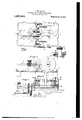
Fig'r'e"n1,"""rs a' 'pl'.ii1 view of a grinding machine embodying; in'y invention.
" Fig. 2,"is',`a section of the saine cut through at'theline A, A, on Fig. 1.
Figa 3, is-a transverse section broken away, illustratingv 'the rocking frame and gear.
Figs. 4 and 5 are fragmentary transverse sectional views of details.
In Fig. 11 the grinding wheel 1 is shown carriedby the power shaft 3, which is journaied in the main frame 2. 'ihe power shaft carries at one en d the power pulley 4 and the other end is operatively connected, and gives motion to the' flexible driving ',sliaft-s 5 through the chain and spur geur shown or. Figs. 1 and 3. The flexible driving shafts 5 are shown as :journaled in the rocking frame (i. The 'latter is carried by the shaft 7 as shown in Figs. '2 and 3, and is provided with the Vsprin,f ,rs 8, H, which are attached at the other 'end t-o the maiwfiana: 9 as .shown on Fig. l. l`be.-;o springs operatel to normally retain the rocking frame in an advanced position pro\ idiug a yielding support fe the material. and retaining' the lens in ope.ativc contact with the grinding face. 'iho shaft 7 is imiriialed in tlaboss 18 of the main ,frame n: as shown in Figs. 2 and L.
Specification uf Letters Patent.
Patented Aug. ,21, 1917.
AppiieatirmV filed Decembcr3,1914. Serial N0. 875,299.
A protractor 9. is carried by the rocking' frame (i, as shown in the different ii ures, and hears on its face a graduated sea eby which the angle at which the lens carried by' the clutch shall be presented to the'grinding ..60 face may be determined when the.spfring-l clip 10, .shown in the diiferentiiguress L' clamped in operative. position. VThe clip 10 Y' is adjustably inountedon the, protraetor 9' ,y
as shown, thethun rlg -screw 11 beingused to clampv it in position. 4'[`he:.jmi-1s.of 'the'clip 10 .have journaled ,triiereimthe :innerends fof and are provided withV gears 12,'12 which are operatively connected, as shown and indicated iu Figs. 1 and 2, with the gea-rs'l.' lf3 of the friction clutch, which are carried bv the clip 1U as Shown, through thefnter-- mediate gear 1i), 19 also carriedby said elip The outer sections ofy the drivingfshaftt-S* flexible material .in a tubular sleeve." "The ed ou shaft 7, which nceeives motion through',
the sprocket chain 21`f`froim the main 2i, as sliown in`i1`igs. 'l'and`3.
The jaws of thc spring clip 10 are in'a'in'- tained in operativel position by the' Spring' 20, lshown in Fig. l, which spreads the han'- dles 1U and 10" and contracts the iaws; a pattern 1G. aLSo shown in said ligureheid with the material in the clutch ofthe jaws,-
bears on a sto 17, shown in Figs. 1 and 2, and controls t ie shaping of the lens in the .setting operation.
In n'iounting my attachment on any "grinding machine of the type illustrated in my flexible. shaft4 and handles are released setting the clutch. A
'llie clip is then moved to the proper angle :xa iudirated on the protraetor scale to set tin,- leus or to produce 'the desired bevel of the rim: the thumbscrew is then set locking the clip in operative position and the power is turned on.
Havingl thus specified, shown and described t invention:
1. In a machine for grinding the rims of optical lenses, in combination, a mainframe, a grinding wheel thereon, a second frame 1 mounted to rock on the ina-in'frar'ne, a driving means having rigid and flexible sections and mounted in the second frame, a rotary clutch driven by the driving means, a spring clip carryin the clutch and adjustably i5 mounted on t ie rocking frame to permit the Alens to be positioned for producing a flat rim or beveling the ed es at an desired angle, and means for con orming t e motion of the rocking frame to the curvature of the 2o periphery of the lens.
2. In a machine for grinding the rims ofv optical lenses, in combination, a main frame,
a grinding wheel thereon a second frame mounted to rock on the main frame, a sectional driving means havin rigid and flexvible connections supported y said rocking :frame, 'said frame being rocked by the same isouree of power ns that which actuates the '.grindin wheel, a spring clip adjustably mount on said rocking frame, a rotary clutch carried by said spring clip, the flexible sectionsbf said driving means giving motion to said clutch' whereby the lens is adapted to be rotated in operative position 1.5 :for ad'ustabiy producing a flat rim or bevcling t e edges thereof at any desired angle,
a pattern and a stop.
3. In a machine for grinding the rims of optical lenses, in combination, a main frame,
0 a grinding wheel thereon, a second frame mounted forrockiiig movement. on the main e same, I claim us novel and my frame, a driving means mounted. on said frame, 'said driving means and grinding wheel bein driven rom the same source o power, sai driving means including two outer rigid sections 'ournaled in the rocking frame through w ich it receives motion,
a protractor fixed 'to the main frame, a spring clip adjustably mounted on said prol tractor, a rotary lens clutch carried by said so clip, said driving means including twflexible inner sections adapted to impart motion to such clutch, said protractor being gradu.
ated to indicate the grinding angle when-the clip is in operative 'tionand, means for 55 conforming the motion of the rockfngflframe to the-curvature of the periphery of t 'e lens. 4. In a machine for grinding the rims of optical lenses in combination, a main frame, a grinding wheel mounted on said frame, a second frame mounted for rocking movementon 'the main frame, adriving.meais carried bysaid rocking frame said drivingmeans and said grindin whee being driven from the samel source o power, said driving U means includin two outer and rigid sections through w ich it receives motion and two flexible inner sections, a clip adjustably mounted on the rocking frame, a rotary clutch carried b said clip, the inner sections of the riving means imparting mesv tion to said clutch wherebyto rotate,
in such adjustable o rative position as may, 1f be re uired to beve the of., thelens,at any esired angle, and means for'confoi'xnf-?s ing the-motion of the roc-king 4fratrie to thecurvature of the periphery of the lens.
MAURICE MOLINEAUX. Witnesses:
J fans Ksn'ron, VVnsoN W. Hoovns.
Priority Applications (1)
| Application Number | Priority Date | Filing Date | Title |
|---|---|---|---|
| US87529914A US1237366A (en) | 1914-12-03 | 1914-12-03 | Apparatus for grinding optical lenses. |
Applications Claiming Priority (1)
| Application Number | Priority Date | Filing Date | Title |
|---|---|---|---|
| US87529914A US1237366A (en) | 1914-12-03 | 1914-12-03 | Apparatus for grinding optical lenses. |
Publications (1)
| Publication Number | Publication Date |
|---|---|
| US1237366A true US1237366A (en) | 1917-08-21 |
Family
ID=3305185
Family Applications (1)
| Application Number | Title | Priority Date | Filing Date |
|---|---|---|---|
| US87529914A Expired - Lifetime US1237366A (en) | 1914-12-03 | 1914-12-03 | Apparatus for grinding optical lenses. |
Country Status (1)
| Country | Link |
|---|---|
| US (1) | US1237366A (en) |
-
1914
- 1914-12-03 US US87529914A patent/US1237366A/en not_active Expired - Lifetime
Similar Documents
| Publication | Publication Date | Title |
|---|---|---|
| US1237366A (en) | Apparatus for grinding optical lenses. | |
| US1659964A (en) | Bevel-edging machine | |
| US1221858A (en) | Apparatus for producing toric lenses. | |
| JPS58181556A (en) | Machine for processing lens | |
| US1521116A (en) | Machine for beveling the edges of optical lenses | |
| US2419543A (en) | Means and methods of abrading | |
| US2175719A (en) | Lens edging machine | |
| US1973527A (en) | Lens grinding machine | |
| US1455863A (en) | Lens-edging machine | |
| GB295718A (en) | Improvements in a device for grinding and polishing spherical and aspherical lenses | |
| US1984074A (en) | Lens grinding machine | |
| US108822A (en) | Improvement in machines for grinding and polishing metal | |
| US1773386A (en) | Apparatus for gear grinding | |
| US1184517A (en) | Grinding-machine. | |
| US1457855A (en) | Machinery for beveling the edges of glass lenses and the like | |
| JPH0475870A (en) | Surface lap polishing machine | |
| US886212A (en) | Lens grinding and polishing machine. | |
| US927949A (en) | Lens-grinding machine. | |
| US743033A (en) | Drill-grinding machine. | |
| US1833010A (en) | Machine for forming electrical coils, etc. | |
| US1651532A (en) | Lens-edging machine | |
| US1546453A (en) | Automatic grinder for twist drills | |
| US3834089A (en) | Monowheel plastic lens edger | |
| US1313702A (en) | Machine | |
| US583670A (en) | Apparatus for producing ellipsoidal lenses |