US1237361A - Automatic weighing-truck. - Google Patents
Automatic weighing-truck. Download PDFInfo
- Publication number
- US1237361A US1237361A US84642014A US1914846420A US1237361A US 1237361 A US1237361 A US 1237361A US 84642014 A US84642014 A US 84642014A US 1914846420 A US1914846420 A US 1914846420A US 1237361 A US1237361 A US 1237361A
- Authority
- US
- United States
- Prior art keywords
- truck
- platform
- weighing
- bar
- goods
- Prior art date
- Legal status (The legal status is an assumption and is not a legal conclusion. Google has not performed a legal analysis and makes no representation as to the accuracy of the status listed.)
- Expired - Lifetime
Links
- 238000005303 weighing Methods 0.000 description 15
- 230000007246 mechanism Effects 0.000 description 11
- 238000000034 method Methods 0.000 description 5
- 230000009471 action Effects 0.000 description 1
- 230000008901 benefit Effects 0.000 description 1
- 230000006835 compression Effects 0.000 description 1
- 238000007906 compression Methods 0.000 description 1
- 230000000994 depressogenic effect Effects 0.000 description 1
- 230000000694 effects Effects 0.000 description 1
- 230000007775 late Effects 0.000 description 1
- 230000004048 modification Effects 0.000 description 1
- 238000012986 modification Methods 0.000 description 1
- 230000001681 protective effect Effects 0.000 description 1
Images


Classifications
-
- G—PHYSICS
- G01—MEASURING; TESTING
- G01G—WEIGHING
- G01G23/00—Auxiliary devices for weighing apparatus
- G01G23/18—Indicating devices, e.g. for remote indication; Recording devices; Scales, e.g. graduated
Definitions
- My invention relates to improvements in automatic weighing trucks adapted to use in connection with any weighing station where' a true record of weights is usually kept.
- the object of my invention is to provide a truck, which automatically will at the same time, as a package of goods is delivered present in printed form the exact weight of said package of goods.
- My invention consists of any ordinary truck so arranged and adapted by certain accessories and registering devices as will effect a simultaneous presentation of weights ;oflgoods carried on said trucks with the delivery of said goods.
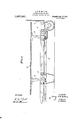
- Figure 1 illustrates a side elevation of an ordinary hand truck, surmounted by a receiving platform for goods.
- Fig. 2 is a plan View of Fig. 1.
- Fig. 3 illustrates' mechanism in elevation, whereby the registered weights of packages of goods are collected.
- Fig. 4 is a plan view of same.
- Fig. 5 and Fig. 6 are eXtended and special views of certain details pertaining to' registration mechanism.
- Fig. 7 illustrates the method of printing and registering weightsand how same are automatically delivered to be torn off and entered record books, usually kept at any weighing station.
- an ordinary i hand truck (1) is shown in elevation constructed as is usual, although it must be platform (2) or any other shaped receptacle for goods in the form of barrels, boxes or the like,
- gear-racks (3) forming at the same timesupports and guides for said platform (2) or receptacle.
- These gear-racks (3) mesh with gear-wheels (ft) and said gear-'wheels are also gearing with a pair of horizontal racks (5) with which is connected the spring 6, through the intermediate cross shaft 4:0 uniting the horizontal racks 5.
- the device (27) here illustrated is composed of a paper roll (28); the paper strip mounted on said roll is carried on the inside of a resistance piece (29) and between a stationary piece (30) and the slightly corrugated wheel (31); as the button (12)' presses against the sliding pins with engraved heads (26) the tape (32) suitably prepared with printers ink 1S imprinting on paper strip carriedby roll (28) the respective weights of goods carried by platform (2); as the button (12) with its elongation is caused to return to its normal or inactive position by reason of 'spring (34), Fig. 7, it will b means of link-rack gearing with pinion 35) cause the corrugated wheel (31) to feed or pull the paper strip as carried by roll (28) the imprinted weight can thus be readly torn ofl and entered as wanted.
- hatched feature of Fig. 7 marked by the numeral (27) simply means a protective casing around the moving parts of mechanism, and the hatched section marked (36) is an end view of one of the arms of above truck (1).
- the means for controlling the mechanism by which a record is made of the weight placed upon the platform 2 are carried by one of the handles 41 of the truck.
- a distinct advantage is incident to this arrangement because the truck must be at rest and supported in a horizontal position as indicated in Fig. 1 when the load upon the platform is weighed, in order that the weight may act upon the weighing devices on vertical lines; and before the load thus weighed can be moved the handles 41 must be grasped, preparatory to raising them; and when this is done, and simultaneously therewith, the button 12 may be pushed by a nger of one of the hands used in graspng the handles 41 and a record of the weight then' made.
- the parts designated 7, 8 and 9 are adjustable stops for determining the extent to which the slide bars, 20, 21 and 22, carrying the printing devices, may be moved' a that of these stops the wheel 9 controls the movements of the units bar 20, the notched bar 8 controls the movements of the tens bar 21, and the notched bar 7 the movements of the hundreds bar 12.
- the units stop a wheel with long teeth, such as shown in Fig. 4, the faces of the teeth on one side being inclined and arranged to be engaged by the contact piece 39, having also an inclined face.
- the stop 8 for the tens bar is a plate provided with a series of teeth, each of which is again notched or pro- 4 vided with a succession of ten stops arranged along a diagonal line; while the stop piece 7 for the hundreds bar is notched regularly and along an inclined line, the
- a weighing truck the combination, with a hand truck, of a movable platform carried thereby, weighin mechansm connected with the said plat orm, printing devices for making records of the weights of the articles weighed, means connected with the weighing mechanism by which the sebting of the printing devices is controlled, and means supported by one of the'handles of the truck in position to be readily operated when such handle is grasped, for Operating the printing devices.
- the oombination, with a hand truck, of weighing mechanism carried thereby including a movable platform, printing devices for makin records of the weights of the articles weig ed, means connected with the weighing mechanism by which the setting of the printing devices s controlled, and means supported by one of.
Landscapes
- Physics & Mathematics (AREA)
- General Physics & Mathematics (AREA)
- Printers Characterized By Their Purpose (AREA)
Description
W I TNESSES //l/l/ I' IV 1 I'Jl/ //////7 1 I l I G., W, W. MATTSON.
Patented Aug. 21, 1917.
3 SHEETS-SHEET I.
IN VEN TOR.
.Cu ta ATTORNEYS.
G. W. 'W. MATTSON.
AUTOMATIC WEIGHING TRUCK.
APPLICATION FILED JUNE 22, 1914.
1 ,237,36 1 Patented Aug. 21, 1917.
3 SHEETS-SHEET 2.
INVNTOR.
A TTORNE YS.
G. W. W. MATTSON.
AUTOMATIC WEIGHING TRUcK APPLICATIN FILED !UNE 22. 1914.
1,237,361. Patented Aug. 21, 1917.
3 SHEETS-SHEET 3.
WITNESSES A TTORNE Ys.
GEORGE W. W. MATTSON, OF SAN FRANCISCO, GALIFORNIA.
AUTOMATIC WEIGHING-TRUCK.
Specificaton of Letters Patent.
Patented Au 21, 1,917.
Application filed June 22, 1914. Serial No 846,420.
To all whom 'it may conccrn Be'it known that I, GEORGE W. lV. MATT- soN, a citizen of theUnited States, and residentof San Francisco, in the State of California, (whose post-office address is 166 Park street, San Francisco,) have invented new and useful Improvements in Automatic WVeighing-Trucks, of which the following is a specification.
My invention relates to improvements in automatic weighing trucks adapted to use in connection with any weighing station where' a true record of weights is usually kept.
The object of my invention is to provide a truck, which automatically will at the same time, as a package of goods is delivered present in printed form the exact weight of said package of goods.
My invention consists of any ordinary truck so arranged and adapted by certain accessories and registering devices as will effect a simultaneous presentation of weights ;oflgoods carried on said trucks with the delivery of said goods.
In' reference to the sheets of drawings forming part of this specification, the mode of. operation will be fully and clearly set forth and similar numbers of reference indicate like parts( Figure 1 illustrates a side elevation of an ordinary hand truck, surmounted by a receiving platform for goods.
Fig. 2 is a plan View of Fig. 1.
Fig. 3 illustrates' mechanism in elevation, whereby the registered weights of packages of goods are efected.
Fig. 4 is a plan view of same.
Fig. 5 and Fig. 6 are eXtended and special views of certain details pertaining to' registration mechanism.
Fig. 7 illustrates the method of printing and registering weightsand how same are automatically delivered to be torn off and entered record books, usually kept at any weighing station.
Now referring to Fig. 1, an ordinary i hand truck (1) is shown in elevation constructed as is usual, although it must be platform (2) or any other shaped receptacle for goods in the form of barrels, boxes or the like,
Attached to said platform are gear-racks (3) forming at the same timesupports and guides for said platform (2) or receptacle. These gear-racks (3) mesh with gear-wheels (ft) and said gear-'wheels are also gearing with a pair of horizontal racks (5) with which is connected the spring 6, through the intermediate cross shaft 4:0 uniting the horizontal racks 5. Thus is the vertical movement of said platform or receptacle converted into a horizontal one and this horizontal movement is opposed by the action of a compression spring (6), and thus will the platform or receptacle assume its normal position after goods have been deposited or emptied from same by reason of the reslience of said spring (6). I i
The registering ofweights is efiected by the goods themselves, asthey are Testing' on receiving platform To this platform (2) are attached notched plates (7) (8) and the like; these plates (7 (8) and the like are notched thus that according to depression of platform (2) by reason of the weight of goods deposited on same, the plates (7 (S) and the like will assume a corresponding position, the movement of platform (2) by above reason will also operate the notched wheel 9 causing it to have a revolution according to depression'of platfornr (17), (18) and (19) are by suitable pins or bolts attached to the sliding bars (20), (21) and The bell crank lever 13 will readily assume its original or inactive position by means of spring 34, mounted on its turning fulcrum.
Attached to these sliding bars (20), (21) and (22) are freely sliding pins (23), (24:) and (25) with enlarged heads and these heads carry suitably engraved numerals denoting weights. As now the button (12) is pressed it will transmit this pressure to said freely sliding pins (23), (24) and"(25) and cause an imprint to be efiected; see Fig. 7 to more clearly illustrate this method of eifecting an imprint of the different weights reference to Fig. 7 is made. The device (27) here illustrated is composed of a paper roll (28); the paper strip mounted on said roll is carried on the inside of a resistance piece (29) and between a stationary piece (30) and the slightly corrugated wheel (31); as the button (12)' presses against the sliding pins with engraved heads (26) the tape (32) suitably prepared with printers ink 1S imprinting on paper strip carriedby roll (28) the respective weights of goods carried by platform (2); as the button (12) with its elongation is caused to return to its normal or inactive position by reason of 'spring (34), Fig. 7, it will b means of link-rack gearing with pinion 35) cause the corrugated wheel (31) to feed or pull the paper strip as carried by roll (28) the imprinted weight can thus be readly torn ofl and entered as wanted.
It must be understood that this device is open to considerable modification and I do not wish to be understood as claiming this particular device, but any method found simple and practical will be utilized in effecting a perfect registration of weights carried by above trucks.
It is seen that in the illustration Fig. 3 only three bars numbered respectively (20), (21) and (22) are shown; thus units, tens and hundreds only may be utilized. Fur-' ther extension may at times be advisable and the method illustrated lends itself readily to this, wherefore, I must distinctly assert that I do not curtail or limit myself to above, but wish to claim any practical extension of above method.
The pieces numbered respectively 37, 38
' and 39 and attached to sliding bars 20, 21
and 22 will by movement of said sliding bars be carried up against notched lates 7, 8 and wheel (9) respectively carre by the platform 2, the extent to which the latter is depressed determining the positions these stop devices occupy and hence the eXtent to which the sliding bars may be moved.
The hatched feature of Fig. 7 marked by the numeral (27) simply means a protective casing around the moving parts of mechanism, and the hatched section marked (36) is an end view of one of the arms of above truck (1).
It will be seen, particularly by reference to Fig. 2, that the means for controlling the mechanism by which a record is made of the weight placed upon the platform 2 are carried by one of the handles 41 of the truck. A distinct advantage is incident to this arrangement because the truck must be at rest and supported in a horizontal position as indicated in Fig. 1 when the load upon the platform is weighed, in order that the weight may act upon the weighing devices on vertical lines; and before the load thus weighed can be moved the handles 41 must be grasped, preparatory to raising them; and when this is done, and simultaneously therewith, the button 12 may be pushed by a nger of one of the hands used in graspng the handles 41 and a record of the weight then' made. It will thus be seen that the making of the record soon becomes practically automatic to the person using a truck, and does not require either time or extra movement to efect it. I r i The parts designated 7, 8 and 9 are adjustable stops for determining the extent to which the slide bars, 20, 21 and 22, carrying the printing devices, may be moved' a that of these stops the wheel 9 controls the movements of the units bar 20, the notched bar 8 controls the movements of the tens bar 21, and the notched bar 7 the movements of the hundreds bar 12. I prefer for the units stop a wheel with long teeth, such as shown in Fig. 4, the faces of the teeth on one side being inclined and arranged to be engaged by the contact piece 39, having also an inclined face. The stop 8 for the tens bar is a plate provided with a series of teeth, each of which is again notched or pro- 4 vided with a succession of ten stops arranged along a diagonal line; while the stop piece 7 for the hundreds bar is notched regularly and along an inclined line, the
distance between the notches being equal to the distance between the main or larger teeth of the bar 8.
Having thus described my invention, what I claim and desire to secure by Letters Patent is:
1. In a weighing truck, the combination, with a hand truck, of a movable platform carried thereby, weighin mechansm connected with the said plat orm, printing devices for making records of the weights of the articles weighed, means connected with the weighing mechanism by which the sebting of the printing devices is controlled, and means supported by one of the'handles of the truck in position to be readily operated when such handle is grasped, for Operating the printing devices.
2. In a weighing truck, the oombination, with a hand truck, of weighing mechanism carried thereby including a movable platform, printing devices for makin records of the weights of the articles weig ed, means connected with the weighing mechanism by which the setting of the printing devices s controlled, and means supported by one of.
also Operating them to cause a printed reoord to be made.
3. The combination with weighing mechanism, of a set of sl'ding bars for units, tens, hundreds, etc., each carrying printng devices, a set of stops connected with and operated by the Weighing mechanism, the stop for the units bar being a wheel With long teeth having inclined faces, the stop for the tens sliding bar being a toothed bar the separate teeth of which are themselves formed With graduated stops, and the stop i'or the hundreds sliding bar being a graduated bar, and means for forcing the said sliding bars against the stops to bring the printing devices into printng position after the stops have been set by the weighing mechanism.
4:. The combination With Weighing mechameans whose movements are controlled respectively by the said stops, nianually controlled means for movng the said sliding bars against the stops after the latter have been set by the Weighing mechanism, including a yielding connection With each bar, and means also connected With the said manually controlled means for causing a record to be made from the printing devices after they have been brought to printing position by the movements of the said slidng bars.
In testimony Whereof I afiiX ny signature in the presence of two witnesses, this seventeenth day of June, A. D. 1914.
GEORGE XV. W'. MATTSON.
Witnesses:
Gr. M. BALL,
F. C. FLEDNER.
copies of this patent' may be obtained tor five cents each, by addressng the "Gommissioner of Patents, Washington, D. C.
Priority Applications (1)
| Application Number | Priority Date | Filing Date | Title |
|---|---|---|---|
| US84642014A US1237361A (en) | 1914-06-22 | 1914-06-22 | Automatic weighing-truck. |
Applications Claiming Priority (1)
| Application Number | Priority Date | Filing Date | Title |
|---|---|---|---|
| US84642014A US1237361A (en) | 1914-06-22 | 1914-06-22 | Automatic weighing-truck. |
Publications (1)
| Publication Number | Publication Date |
|---|---|
| US1237361A true US1237361A (en) | 1917-08-21 |
Family
ID=3305180
Family Applications (1)
| Application Number | Title | Priority Date | Filing Date |
|---|---|---|---|
| US84642014A Expired - Lifetime US1237361A (en) | 1914-06-22 | 1914-06-22 | Automatic weighing-truck. |
Country Status (1)
| Country | Link |
|---|---|
| US (1) | US1237361A (en) |
-
1914
- 1914-06-22 US US84642014A patent/US1237361A/en not_active Expired - Lifetime
Similar Documents
| Publication | Publication Date | Title |
|---|---|---|
| US1237361A (en) | Automatic weighing-truck. | |
| US1728826A (en) | Registering stamp | |
| US2044367A (en) | Ticket printing, issuing, and accounting machine | |
| US583878A (en) | Printing apparatus | |
| US994081A (en) | Ticket printing and delivering machine. | |
| US1013741A (en) | Cash-register or check-till. | |
| US559182A (en) | macdonald | |
| US327178A (en) | Fabric-measuring machine | |
| US592590A (en) | Vote recording apparatus | |
| US695115A (en) | Ticket issuing, printing, and recording machine. | |
| US470423A (en) | ekroth | |
| US965434A (en) | Measuring and recording machine. | |
| US1205315A (en) | Printing-press. | |
| US614977A (en) | pottin | |
| US1607705A (en) | Stamping and registering or counting apparatus | |
| US984362A (en) | Register for weighing-scales. | |
| US714228A (en) | Ticket issuing, recording, and printing machine. | |
| US1373245A (en) | Conductors ticket | |
| US911518A (en) | Fare-register. | |
| US1335070A (en) | Computing and printing scale | |
| US379106A (en) | Package-register | |
| US1645545A (en) | sekinger | |
| US613164A (en) | Voting-machine | |
| US620610A (en) | Voting-machine | |
| US792201A (en) | Recording-scale. |