US1237333A - Automatic film control. - Google Patents
Automatic film control. Download PDFInfo
- Publication number
- US1237333A US1237333A US8705216A US8705216A US1237333A US 1237333 A US1237333 A US 1237333A US 8705216 A US8705216 A US 8705216A US 8705216 A US8705216 A US 8705216A US 1237333 A US1237333 A US 1237333A
- Authority
- US
- United States
- Prior art keywords
- film
- spring
- shutter
- casing
- wheel
- Prior art date
- Legal status (The legal status is an assumption and is not a legal conclusion. Google has not performed a legal analysis and makes no representation as to the accuracy of the status listed.)
- Expired - Lifetime
Links
- 239000002184 metal Substances 0.000 description 3
- 238000004804 winding Methods 0.000 description 3
- 102000010029 Homer Scaffolding Proteins Human genes 0.000 description 2
- 108010077223 Homer Scaffolding Proteins Proteins 0.000 description 2
- 238000010276 construction Methods 0.000 description 2
- RUPBZQFQVRMKDG-UHFFFAOYSA-M Didecyldimethylammonium chloride Chemical compound [Cl-].CCCCCCCCCC[N+](C)(C)CCCCCCCCCC RUPBZQFQVRMKDG-UHFFFAOYSA-M 0.000 description 1
- 101100114417 Neurospora crassa (strain ATCC 24698 / 74-OR23-1A / CBS 708.71 / DSM 1257 / FGSC 987) con-13 gene Proteins 0.000 description 1
- 229910000831 Steel Inorganic materials 0.000 description 1
- 230000000881 depressing effect Effects 0.000 description 1
- 239000000463 material Substances 0.000 description 1
- 239000010959 steel Substances 0.000 description 1
Images
Classifications
-
- G—PHYSICS
- G03—PHOTOGRAPHY; CINEMATOGRAPHY; ANALOGOUS TECHNIQUES USING WAVES OTHER THAN OPTICAL WAVES; ELECTROGRAPHY; HOLOGRAPHY
- G03B—APPARATUS OR ARRANGEMENTS FOR TAKING PHOTOGRAPHS OR FOR PROJECTING OR VIEWING THEM; APPARATUS OR ARRANGEMENTS EMPLOYING ANALOGOUS TECHNIQUES USING WAVES OTHER THAN OPTICAL WAVES; ACCESSORIES THEREFOR
- G03B17/00—Details of cameras or camera bodies; Accessories therefor
- G03B17/42—Interlocking between shutter operation and advance of film or change of plate or cut-film
Definitions
- This invention relates to devices for the automatic changing of exposed films in cameras to bring an unexposed film into place.
- the object of the invention is to devise a mechanism that will prevent the double exposure of a film and one that will remove the exposed film from behind the lens and bring an unexposed one into exact picture taking position without having it run beyond as is so often the case with cameras at present in use.
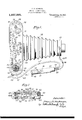
- Figure 1 is a plan view of a camera with my invention in place and shown in dotted lines. Y
- Fig. 2 is a partly sectional rear elevation of the same camera with the back plate removed.
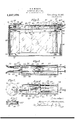
- Fig. 3 shows a vertical longitudinal section through my shutter and film operating hand piece.A
- Fig. 4 is a view of the same parts as Fig. 3 but is a section taken along the line 4-4 of Fig. 3.
- Fig. 5 is a partly sectional plan view of one of the elements of Amy hand piece.
- Fig. 6 is a plan view of my tape controlling wheel.
- Fig. 7 is a partly sectional side elevation thereof.
- 11 indicates the body portion of a camera, 12 a bellows and 13 the shutter holding frame, 14 a spool, of ilm 15 just inserted in the camera, 16 an empty spool on which the film is to be wound.
- 17 and 18 represent the usual spring detents for the spools.
- 19 indicates a shaft suraCCOIIlrounded by a swivel plate ,719 carrying a pivoted handle 2O provided with asfinger 21.v This shaft extends into the casing of the ed to normally co-act with a clutch member..
- A. spring 22a is provided between the clutch members adapted to normally maintain them in contact with each other.
- the drum 24 is divided into two sections 24a and 24h, the upper of which, 24a is adapted to carry a spring 35.
- 25 and 26 represent upper and lower plates which carry my improved mechanism.
- 27 indicates a shaft'having a pivoted handle 28 with a inger 29.
- 30 represents a clutch member adaptedto co-act with but normally disengaged from a clutch member 31 carried by a drum 32.
- a spring such as 33 may keep the clutch members apart.
- This drum 32 is adapted to have wound upon it, a perforated tape 34.
- Tape 34 is also adapted to be wound upon the drum 24 in the section 24b and passes over a control wheel 36 journaled intermediate of the drums. 'This wheel is providedy with yprojecting teeth 37 adapted to engage theperforations 38 of the tape.v While I prefer to make the tape of steel, I'may use any suitable material.
- a dog 39 is pivoted in my wheel 36, as shown in Fig. 7, and is maintained in extended position by a spring 40. 41 is a stop for the dog 39 when it is retracted against the pressure of the spring 40. 41 represents an opening in the top of the wheel 36 through which the dog 39 extends.
- An operating member is adapted to move in the slots 63 and 64 which comprises two arms 68 and 69 of unequal length.
- 70 represents a toothed rack carried by the arms 68 and 71 a toothed rack carried by the arm 69. These racks are spaced apart lonu gitudinally so that the teeth on the arms are not lcontiguous.
- The. arm 68 has the adjusting pin 58 pivoted to it at 72. This pin 58 is provided with a tooth 73 having a spring 74 bearing upon it to maintain it in a recess 75 as shown. 76 is another recess for adjustment of the device.
- the arms 68 i and 69 are connected together by a connection 77 slidable in the lateral slot 66. 7 8 a lu on the arm 68 slidable in the slot 67, and 9 and 8O are lugs on the arm 69 slidable in the slot 65.
- 81 represents a gear wheel ljournaled in the casin 57 and provided with teeth 82 and 83 a apted to mesh with the gears 70 y ary.
- 84 is a lateral projection on the gear 81 adapted to engage sto 85 on the casing 57.
- 86 shows a helica spring adapted to return the gear 81 after being rotatedby the racks 70 and 71.
- the plate 62 terminates in a stem 87 encircled by a spring 88.
- Stem 87 co-acts with a plunger 89 operating the wire 54 in a casing 90.
- On the opposite side of the gear 81 from the plate 62 is a rod 91 provided with a rack 92 maintained extended by means of a spring 93. This rod terminates in a stem 94 encircled by a spring 95 co-acting with a plunger 96 operating the wire 54 in a casing 97.
- I may provide a pivoted guard 98 to cover ⁇ and protect the push rods 'and 61 when not inuse, as shown in Fig. 1.
- the operation of the device is as follows: The film. is inserted in the camera in the usual manner and the free end thereof threaded into the spool 16.
- the handle 2O is moved to vertical-position which disengages the clutch 22 from the clutch 23 by depressing shaft 19 so that when the shaft 19 is rotated, the drum 24 remains stationary. Rotation of the shaft 19 rotates the spool 16 which brings the first film into place as is usual.
- the camera is prepared for taking the picture as is custom- The picture is taken by operating shot. Inward movement of the rod 60 and.
- the plunger 96 When the rod 91 is pushed in, the plunger 96 will cause the collar 53 in Fig. 2, to be pushed inwardly so that the stem 52 pushes the plate 49 to the left so thatthe lug 50 will be disengaged from the dog 39 of the wheel 36. This will permit the spring 35 to rotate the drum 24 which, through the medium of the tape 34, will cause the winding up on the spool 16 of the exposed film and the unwinding of a new lm. This winding and unuf'inding is controlled by the wheel 36.
- This wheel is of such a size that its circumference is equal to the length of the film, so that one rotation thereof will take one lm away and bring a new one in place.
- the spring 56 returns the stem 52 and the slide 49 so that the lug 50 returns to its initial position and acts as astop for the dog 39 to engage whereby one revolution is made. If deslred,
- the lug 51 is provided so that-the wheel 36 may be stopped iist at a half revolution and then at a full one.
- the spring 35 is 'strong enough and the tape 34 is long enough so that one winding will be sufficient to move all the films of the spool into place.
- the drum 32 is loosely journaled on the shaft 27 so that to wind the spring, the handle 28 is moved to a vertical position which depresses clutch member 33 to engage with the clutch member 31 so that the drum 32 is rotated and the spring wo Movement of the tape in this winddirection. moves the wheel 36, which shutter.
- the pin 58, Fig. 4 is pivotally moved to disengage the finger 73 from the notch 75 whereupon the member 68, 77 and 69 is slid to the right'until the finger 73 engages the notch 76.
- movement of the ⁇ push rod 60 will only open the shutter because the rack 70 isvonly half the length of the rack 71 so. that only half a revolution of the wheel 81 takes place at a time.
- the rod 6l must be pushed again to cause a closing of the shutter.
- the springl 88 will return the plate 62 to the right and the rod must be pushed again to close the shutter.
- A- camera including a shutter,shutter operating mechanism, hand pressure means for actuating said mechanism, a casing independent of the camera housing said hand means,.and means carried by said casing for controlling the exposure character of said 2.
- a film camera including a shutter, shutter operating mechanism, hand pressure means for actuating said mechanism, a casing independent of the camera housing said ,hand means, and means carried by said casing for preventing a second opening of the shutter untilthe lm exposed to the first openinghas been changed said means oom-- prising channeled plates, racks in said channels, and algear co-acting with said racks.
- a film camera provided with film spools, spring means connected tothe spool to be filled withl the exposed film, a drum connected to the unexposed film, spool, and a metal tape operatively connecting the spring means wi'th 'the drum whereby a predetermined amount of film may be fed into operative position.
- a film camera provided with film spools, including *spring means lconnected to the spool to be filled with the exposed lm, a
- a metal tape operatively connecting the spring means with the drum and means between the spools for permitting'intermittent movement of' a pre of film may be fed into operative position.
- a film camera including a shutter, hand pressure operated -actuating mechanism therefor', hand pressure actuated film feeding mechanism independent of said previous hand means, a casing adapted to house said hand means, and means in said casing for connecting both of said hand means whereby the lm feeding mechanism may lock the shutter mechanism.
- a film camera including a shutter, hand pressure operated actuating mechanism etermined amount of lsaid tape whereby a predetermined ⁇ amount therefor, hand pressure actuated film feed-i.
- one means may automatically lock and unlock the other.
- a ilm camera including a shutter, hand pressure operated actuating mechanism therefor, hand pressure actuated film feeding mechanism, a casing adapted to house said hand means, and means in said casing operated by the film feeding mechanism foi' automatically locking and unlocking the shutter mechanism comprising teeth adjustably carried on said means in the casing and a gear co-acting therewith.
- a film camera including a shutter, hand pressure operated actuating mechanism therefor, hand' pressure actuated film feeding mechanism, a casing adapted to house said hand means, and means in said casing operated by the film feeding mechanism for automatically locking and unlocking the shutter mechanism comprising teeth on said means'in the casing and a spring actuated gear co-acting therewith.
- a film camera including a shutter, hand pressure operated actuating mechanism therefor, hand pressure actuated'film feeding mechanism, a casing adapted to house said hand means, and means in said casing operated by the film feeding mechanism for automatically locking and unlocking the' shutter mechanism -comprising slidably toothed racks on said means in the casing and a gear therebetween co-acting therewith.
- a camera including a shutter, shutter operating v mechanism, hand pressure means for actuating said mechanism, a casing independent of the camera housing said hand means and means carried by said casing for controlling the exposure character of said shutter comprising a spring pressed channeled plate, racks slidable in vsaid channels and a spring pressed gear co-acting with said racks.
- a camera including a shutter, shutter operating mechanism, hand pressure means for actuating said mechanism, a casing independent of the camera housing said hand means, and means carried by said casing for controlling the exposure character of said shutter comprising a spring pressed channeled plate, racks slidable in said channels, a spring pressed gear co-acting with said racks, and means external of said casing for moving" said racks.
Landscapes
- Physics & Mathematics (AREA)
- General Physics & Mathematics (AREA)
- Details Of Cameras Including Film Mechanisms (AREA)
Description
H. H. HECKMAN.
AUTOMATICFILM CONTROL. APPLICATION FILED MAR. 21, me.
.Patented Aug. "21', 1917.
2 sIIEETs-sIIEET I.
u lvIIIII IIIIIIHUIIIIIN HIIIHH HIIII I TI I Il lzuenor:
.Hom IS7a Jf. Hackman,
H. H. HECKMAN.
AUTOMATIC FILM CONTROL.
APPLICATION FILED MAR. 27. 1916.
Patented Aug. 21, 1917.
2 SHEETS-SHEET 2.
O O O O O O O O O Q ai O UNITED sTATEs PATENT oEEioE.
HOMER H. BECKMAN, 0F FREEPORT, ILLINOIS, ASSIGNOR OF ONE-THIRD T0 E. C. BOWEN, 0F FREEPORT, ILLINOIS.
AUTOMATIC FILM CONTROL.
Specification of Letters Patent.
Patented Aug. 21, 1917.
T 0 all whom t may concern.'
Be it known that I, HOMER I-I. I-IEGKMAN, a citizen of the United States, residing at Freeport, State of Illinois, have invented a new and Vuseful Improvement in Automatic Film Controls, of which the vfollowing is a specification.
This invention relates to devices for the automatic changing of exposed films in cameras to bring an unexposed film into place. The object of the invention is to devise a mechanism that will prevent the double exposure of a film and one that will remove the exposed film from behind the lens and bring an unexposed one into exact picture taking position without having it run beyond as is so often the case with cameras at present in use.
With these objects in view, the invention consists in the arrangement, construction and combination of parts hereinafter de-r scribed and particularly pointed out `in the claims, it being understood that I do not intend to limit myself to the details of construction.
The invention is illustrated in the panying drawings in which:
Figure 1 is a plan view of a camera with my invention in place and shown in dotted lines. Y
Fig. 2 is a partly sectional rear elevation of the same camera with the back plate removed.
Fig. 3 shows a vertical longitudinal section through my shutter and film operating hand piece.A
Fig. 4 is a view of the same parts as Fig. 3 but is a section taken along the line 4-4 of Fig. 3.
Fig. 5 is a partly sectional plan view of one of the elements of Amy hand piece.
Fig. 6 is a plan view of my tape controlling wheel. f
Fig. 7 is a partly sectional side elevation thereof. v In the drawings 11 indicates the body portion of a camera, 12 a bellows and 13 the shutter holding frame, 14 a spool, of ilm 15 just inserted in the camera, 16 an empty spool on which the film is to be wound. 17 and 18 represent the usual spring detents for the spools. 19 indicates a shaft suraCCOIIlrounded by a swivel plate ,719 carrying a pivoted handle 2O provided with asfinger 21.v This shaft extends into the casing of the ed to normally co-act with a clutch member..
23 depending from a drum 24 carried by a sleeve 24 surrounding the shaft. A. spring 22a is provided between the clutch members adapted to normally maintain them in contact with each other. The drum 24 is divided into two sections 24a and 24h, the upper of which, 24a is adapted to carry a spring 35. 25 and 26 represent upper and lower plates which carry my improved mechanism. 27 indicates a shaft'having a pivoted handle 28 with a inger 29. 30 represents a clutch member adaptedto co-act with but normally disengaged from a clutch member 31 carried by a drum 32. A spring such as 33 may keep the clutch members apart. This drum 32 is adapted to have wound upon it, a perforated tape 34. Tape 34 is also adapted to be wound upon the drum 24 in the section 24b and passes over a control wheel 36 journaled intermediate of the drums. 'This wheel is providedy with yprojecting teeth 37 adapted to engage theperforations 38 of the tape.v While I prefer to make the tape of steel, I'may use any suitable material. A dog 39 is pivoted in my wheel 36, as shown in Fig. 7, and is maintained in extended position by a spring 40. 41 is a stop for the dog 39 when it is retracted against the pressure of the spring 40. 41 represents an opening in the top of the wheel 36 through which the dog 39 extends. On the shaft 42 which carries the wheel 36, I place a gear 43 meshing with a larger gear 44 on which I provide'numerals 45 which register consecutively with an opening 46 inthe top casing of the camera. 47 indicates a slide secured to plate 25 by means of rivets 48 and slots 49. This slide has two depending lugs 50 and 51 for engaging the dog 39 of the wheel 36 on opposite sides of the shaft 42. This. slide is operated upon by a stem 52 having a collar 53 therearound operated from a wire containing tube 55. Where the tube 55 enters the camera as at 54a, I provide a detachable connection so that it can be disconnected at this point when the camera is in portable condition. 56 is a spring encircling the stem 52.
The tube 55 from the camera just described and the tube 55ZA from the shutter l64 therein, which slots have grooves 65, 66
and 67 extending laterally therefrom. An operating member is adapted to move in the slots 63 and 64 which comprises two arms 68 and 69 of unequal length. 70 represents a toothed rack carried by the arms 68 and 71 a toothed rack carried by the arm 69. These racks are spaced apart lonu gitudinally so that the teeth on the arms are not lcontiguous. The. arm 68 has the adjusting pin 58 pivoted to it at 72. This pin 58 is provided with a tooth 73 having a spring 74 bearing upon it to maintain it in a recess 75 as shown. 76 is another recess for adjustment of the device. The arms 68 i and 69 are connected together by a connection 77 slidable in the lateral slot 66. 7 8 a lu on the arm 68 slidable in the slot 67, and 9 and 8O are lugs on the arm 69 slidable in the slot 65.
81 represents a gear wheel ljournaled in the casin 57 and provided with teeth 82 and 83 a apted to mesh with the gears 70 y ary.
and 71. 84 is a lateral projection on the gear 81 adapted to engage sto 85 on the casing 57. 86 shows a helica spring adapted to return the gear 81 after being rotatedby the racks 70 and 71. The plate 62 terminates in a stem 87 encircled by a spring 88. Stem 87 co-acts with a plunger 89 operating the wire 54 in a casing 90. On the opposite side of the gear 81 from the plate 62 is a rod 91 provided with a rack 92 maintained extended by means of a spring 93. This rod terminates in a stem 94 encircled by a spring 95 co-acting with a plunger 96 operating the wire 54 in a casing 97.
I may provide a pivoted guard 98 to cover` and protect the push rods 'and 61 when not inuse, as shown in Fig. 1.
The operation of the device is as follows: The film. is inserted in the camera in the usual manner and the free end thereof threaded into the spool 16. The handle 2O is moved to vertical-position which disengages the clutch 22 from the clutch 23 by depressing shaft 19 so that when the shaft 19 is rotated, the drum 24 remains stationary. Rotation of the shaft 19 rotates the spool 16 which brings the first film into place as is usual. Then the camera is prepared for taking the picture as is custom- The picture is taken by operating shot. Inward movement of the rod 60 and.
the plate 62 through the medium of the plunger 89 will cause the shutter to open and close and the spring 88 will cause the return of the plate and the rod to initial position. Inward movement of the plate through the rack 71 and the teeth 83 on the gear wheel 81 will'cause the latter to rotate in a clockwise direction (looking at Fig. 3) until the lug 84 engages the stop 85. This will prevent the operation of'the rod 60 and the shutter again until the film has been changed. The rack 92 on the rod 91 engages the gear wheel 81 to maintain it against the pressure of the spring 86 in this locking position. Then if the push rod 61 is moved inwardly, the rack 92 will ride over the teeth on the wheel 81 because of the spring 93 until the rack is free from the wheel whereupon the spring 86 will return the wheel to initial position1 as shown in Fig. 3. The spring 94 will cause the-rod 91 to be moved back again until the rack 92 engages the wheel 81. When therod 60 is moved in again, rotation of the wheel 81 thereby will extend'the rod 61 to its' full outward position.
When the rod 91 is pushed in, the plunger 96 will cause the collar 53 in Fig. 2, to be pushed inwardly so that the stem 52 pushes the plate 49 to the left so thatthe lug 50 will be disengaged from the dog 39 of the wheel 36. This will permit the spring 35 to rotate the drum 24 which, through the medium of the tape 34, will cause the winding up on the spool 16 of the exposed film and the unwinding of a new lm. This winding and unuf'inding is controlled by the wheel 36.
This wheel is of such a size that its circumference is equal to the length of the film, so that one rotation thereof will take one lm away and bring a new one in place. As soon as the plate 49 moves to the left and frees the lug 50 from the dog 39 the spring 56 returns the stem 52 and the slide 49 so that the lug 50 returns to its initial position and acts as astop for the dog 39 to engage whereby one revolution is made. If deslred,
the lug 51 is provided so that-the wheel 36 may be stopped iist at a half revolution and then at a full one.
The spring 35 is 'strong enough and the tape 34 is long enough so that one winding will be sufficient to move all the films of the spool into place. The drum 32 is loosely journaled on the shaft 27 so that to wind the spring, the handle 28 is moved to a vertical position which depresses clutch member 33 to engage with the clutch member 31 so that the drum 32 is rotated and the spring wo Movement of the tape in this winddirection. moves the wheel 36, which shutter. Y
Les?
movement is permitted by the pivoted dog 39 which will pivotally move to a iush position when it is engaged by the lugs or 51.
If instead of a snap shot as above described, it is desired to take, a time picture, the pin 58, Fig. 4, is pivotally moved to disengage the finger 73 from the notch 75 whereupon the member 68, 77 and 69 is slid to the right'until the finger 73 engages the notch 76. In this position, movement of the `push rod 60 will only open the shutter because the rack 70 isvonly half the length of the rack 71 so. that only half a revolution of the wheel 81 takes place at a time. The rod 6l must be pushed again to cause a closing of the shutter. The springl 88 will return the plate 62 to the right and the rod must be pushed again to close the shutter.
n What I claim is: 1. A- camera including a shutter,shutter operating mechanism, hand pressure means for actuating said mechanism, a casing independent of the camera housing said hand means,.and means carried by said casing for controlling the exposure character of said 2. A film camera including a shutter, shutter operating mechanism, hand pressure means for actuating said mechanism, a casing independent of the camera housing said ,hand means, and means carried by said casing for preventing a second opening of the shutter untilthe lm exposed to the first openinghas been changed said means oom-- prising channeled plates, racks in said channels, and algear co-acting with said racks.
3. A film camera provided with film spools, spring means connected tothe spool to be filled withl the exposed film, a drum connected to the unexposed film, spool, and a metal tape operatively connecting the spring means wi'th 'the drum whereby a predetermined amount of film may be fed into operative position.
4:. A film camera provided with film spools, including *spring means lconnected to the spool to be filled with the exposed lm, a
. drum connected to the unexposed lm, spool,
a metal tape operatively connecting the spring means with the drum and means between the spools for permitting'intermittent movement of' a pre of film may be fed into operative position.
5. A film camera including a shutter, hand pressure operated -actuating mechanism therefor', hand pressure actuated film feeding mechanism independent of said previous hand means, a casing adapted to house said hand means, and means in said casing for connecting both of said hand means whereby the lm feeding mechanism may lock the shutter mechanism.
6. A film camera including a shutter, hand pressure operated actuating mechanism etermined amount of lsaid tape whereby a predetermined `amount therefor, hand pressure actuated film feed-i.
connecting both of said hand means whereby.
one means may automatically lock and unlock the other.
7 A ilm camera including a shutter, hand pressure operated actuating mechanism therefor, hand pressure actuated film feeding mechanism, a casing adapted to house said hand means, and means in said casing operated by the film feeding mechanism foi' automatically locking and unlocking the shutter mechanism comprising teeth adjustably carried on said means in the casing and a gear co-acting therewith.
8. A film camera including a shutter, hand pressure operated actuating mechanism therefor, hand' pressure actuated film feeding mechanism, a casing adapted to house said hand means, and means in said casing operated by the film feeding mechanism for automatically locking and unlocking the shutter mechanism comprising teeth on said means'in the casing and a spring actuated gear co-acting therewith.
9. A film camera including a shutter, hand pressure operated actuating mechanism therefor, hand pressure actuated'film feeding mechanism, a casing adapted to house said hand means, and means in said casing operated by the film feeding mechanism for automatically locking and unlocking the' shutter mechanism -comprising slidably toothed racks on said means in the casing and a gear therebetween co-acting therewith.
10. A camera including a shutter, shutter operating v mechanism, hand pressure means for actuating said mechanism, a casing independent of the camera housing said hand means and means carried by said casing for controlling the exposure character of said shutter comprising a spring pressed channeled plate, racks slidable in vsaid channels and a spring pressed gear co-acting with said racks.
l1. A camera including a shutter, shutter operating mechanism, hand pressure means for actuating said mechanism, a casing independent of the camera housing said hand means, and means carried by said casing for controlling the exposure character of said shutter comprising a spring pressed channeled plate, racks slidable in said channels, a spring pressed gear co-acting with said racks, and means external of said casing for moving" said racks.
`pendent`of the camera housing said hand means, and-'means carried by said casing for controlling tl e exposure character of said shutter comprising a spring pressed chandrum connected to the unexposed film spool,
neled plate, racks slidable in said Channels, a perforated metal tape operatively con- 13 a spring pressed lgear co-acting With said neeting the spring means with the drum, racks, and a pivoted lever for moving said and tooth means co-acting with the per- `5 racks. Y forated tape for permitting intermittent 13. Al film camera provided With film movement of 'a predetermined `Vamount of `spools, including spring means connected to film to be fed into operative position. the spool to be filled with the exposed film, a HOMER H. HECKMAN.
Priority Applications (1)
| Application Number | Priority Date | Filing Date | Title |
|---|---|---|---|
| US8705216A US1237333A (en) | 1916-03-27 | 1916-03-27 | Automatic film control. |
Applications Claiming Priority (1)
| Application Number | Priority Date | Filing Date | Title |
|---|---|---|---|
| US8705216A US1237333A (en) | 1916-03-27 | 1916-03-27 | Automatic film control. |
Publications (1)
| Publication Number | Publication Date |
|---|---|
| US1237333A true US1237333A (en) | 1917-08-21 |
Family
ID=3305152
Family Applications (1)
| Application Number | Title | Priority Date | Filing Date |
|---|---|---|---|
| US8705216A Expired - Lifetime US1237333A (en) | 1916-03-27 | 1916-03-27 | Automatic film control. |
Country Status (1)
| Country | Link |
|---|---|
| US (1) | US1237333A (en) |
-
1916
- 1916-03-27 US US8705216A patent/US1237333A/en not_active Expired - Lifetime
Similar Documents
| Publication | Publication Date | Title |
|---|---|---|
| JPS5847694B2 (en) | jikoshiyori camera | |
| DE3436449A1 (en) | SWITCHING DEVICE FOR THE OPERATING FUNCTION OF A CAMERA WITH FILM REWINDING | |
| GB532610A (en) | Improvements in or relating to photographic cameras | |
| US3253526A (en) | Camera film winding arrangement | |
| US1237333A (en) | Automatic film control. | |
| US2150642A (en) | Photographic camera | |
| GB2030714A (en) | Automatic Camera Lens Cover | |
| US4001849A (en) | Photographic camera for use with film cartridge | |
| US2226161A (en) | Photographic camera | |
| US2282075A (en) | Motor drive operating mechanism for roll film cameras | |
| US2832258A (en) | Cinematographic cameras | |
| US3412665A (en) | Film metering and counting mechanism with shutter interlocks | |
| US4070684A (en) | Shutter release blocking device for foldable camera | |
| US2309382A (en) | Camera mechanism | |
| US2298349A (en) | Safety latch for camera mechanism | |
| US2949831A (en) | Photographic roll film camera | |
| US3637301A (en) | Motion picture camera fadeout fade-in mechanism | |
| US3106142A (en) | Film winding mechanism | |
| US3079850A (en) | Photographic camera with exposure counting device and rewinding attachment | |
| US4147421A (en) | Collapsible camera | |
| US1233929A (en) | Automatic film-winding mechanism for cameras. | |
| US3455224A (en) | Film transporting mechanism for photographic cameras | |
| US2854906A (en) | Film control gear for photographic cameras | |
| US1253078A (en) | Film-winding device for cameras. | |
| US2853929A (en) | Film feeding mechanism |