US1237284A - Fly-screen. - Google Patents
Fly-screen. Download PDFInfo
- Publication number
- US1237284A US1237284A US10916716A US10916716A US1237284A US 1237284 A US1237284 A US 1237284A US 10916716 A US10916716 A US 10916716A US 10916716 A US10916716 A US 10916716A US 1237284 A US1237284 A US 1237284A
- Authority
- US
- United States
- Prior art keywords
- screen
- door
- exit
- bar
- fly
- Prior art date
- Legal status (The legal status is an assumption and is not a legal conclusion. Google has not performed a legal analysis and makes no representation as to the accuracy of the status listed.)
- Expired - Lifetime
Links
Images

Classifications
-
- E—FIXED CONSTRUCTIONS
- E06—DOORS, WINDOWS, SHUTTERS, OR ROLLER BLINDS IN GENERAL; LADDERS
- E06B—FIXED OR MOVABLE CLOSURES FOR OPENINGS IN BUILDINGS, VEHICLES, FENCES OR LIKE ENCLOSURES IN GENERAL, e.g. DOORS, WINDOWS, BLINDS, GATES
- E06B9/00—Screening or protective devices for wall or similar openings, with or without operating or securing mechanisms; Closures of similar construction
- E06B9/52—Devices affording protection against insects, e.g. fly screens; Mesh windows for other purposes
Definitions
- the object of our invention is to provide 1 v I formed ison theinside of the screen-wire 5,
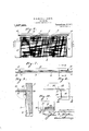
- Figure 1 is an Inside face view of the. upper end of our improved door or windowscreen.
- Fig. 2 is a horizontal section, taken on the line 2-2 of Fig. 1.
- Fig. 3 is a vertical section, with the parts y 7 open or closed 'posltion', weloosely mount Fig. 1 is an enlarged horizontal section,
- Fig. 5 is a view like'the last, butshowing the exit-door closed against. the entrance of bugs, as it should be at night.
- Fig. 6 is an outside face-view of the upper end of our improved door or window screen, with a modified form of exit-door.
- Fig. 7 is a horizontal section, taken through the same on the line 7-7 of Fig. 6.
- Fig. 8 is a vertical section, enlarged, taken on the line 8-8 of Fig. 7. i
- Fig. 9 is a detail plan-view, of a portion of the upper end of the screen, showing the same parts that appear in Fig. 8, and
- Fig. 10 is a detail section, taken on the line 1010, of Fig. 9.
- the numeral 1 designates the top horizontal bar of a door or Window screen, and 2 the upright bars of the same.
- the outer face of the said'top bar 1 is cut the exit of the flies, between the vertical partitions 4', to which latter the upper edge of the screen-wire 5 is attached by the usual tacks and clamping-strip 6.
- cams 11 will engage said staples and force said movable bar and its screen-wire inwardly, and open the exit-door.
- said handles 10 are moved in- 'wardly, toward each other, .to the position in which one of them is shown in F ig, 5, the said cams 11 will force said bar 7 outwardly, and securely close the said exitdooragainst :the entrance of. bugs and the like,
- Said brackets 18, as shown more clearly in Fig. 10, are adapted to hold said door 16 in an open position, by reason of cam locking'lugs 21 engaging a recess 22 in the end V of said door.
- the said door will stay closed reason of its weight holdingit in the closed position. (See Fig. 8).
- the inner lower corner of said door 16 is rounded ofl,.at 23, to permit said door to served, substantially the same as in the form previously described.
- An improved door or window screen having at its upper end inclined exit-passages with vertical-bars between them, screen-wire attached to said vertical-bars covering all but the upper edges of said exitpassages, a suitable movable exit-door arranged to control said passages and prevent the passage ofbugs and other insects into the room, at night, and cam-locks which hold the said dooraiter its adjustment,
Landscapes
- Engineering & Computer Science (AREA)
- Structural Engineering (AREA)
- Life Sciences & Earth Sciences (AREA)
- Insects & Arthropods (AREA)
- Pest Control & Pesticides (AREA)
- Architecture (AREA)
- Civil Engineering (AREA)
- Catching Or Destruction (AREA)
Description
W. H. BETTS & F. BOUGHT.
FLY SCREEN.
APPUCATION FILED JULY 13. 1916.
1917. 2 SHEETS-SHEET I.
Patented Aug. 21'
w. H. BETTS & F. YROUGHT.
FLY SCREEN.
APPLICATION FILED JULY 13. I916- 1,2f3'7,284. Patented Aug. 21, 1917.
v 2 SHEETS-SHEET 2- 1% 6- 15 1a 1 4 15 U E su WILLIAM II. BETTSAND FRANK nouenr, or sr. LOUIS, MISSOURIQ v ELY-SCREEN.
To all whom it may concern? Be it known that we, WILLIAM H. Burrs and FRANK BOUGHT, citizens of the United States, and residents of St. Louis, Missouri, have invented certain new and useful Improvements in Fly-Screens, of'which the following is a specification containing a full,
clear, and exact descriptiomreference being had to the accompanylng'drawlngs, forming a parthereof. I
The object of our invention is to provide 1 v I formed ison theinside of the screen-wire 5,
'and'extends parallel thereto, to form a passage-way for the flies in making their'exit an improved door and windowscreen', which wlll easlly permlt the'flles to escape from a inafter described, and specifically pointed. out in the appended claims.
In the drawings:
Figure 1 is an Inside face view of the. upper end of our improved door or windowscreen.
Fig. 2 is a horizontal section, taken on the line 2-2 of Fig. 1.
' Fig. 3 is a vertical section, with the parts y 7 open or closed 'posltion', weloosely mount Fig. 1 is an enlarged horizontal section,
ofthe parts at the left-hand of Fig. 2, and showing the exit-door in an open position Fig. 5 is a view like'the last, butshowing the exit-door closed against. the entrance of bugs, as it should be at night.
Fig. 6 is an outside face-view of the upper end of our improved door or window screen, with a modified form of exit-door.
Fig. 7 is a horizontal section, taken through the same on the line 7-7 of Fig. 6.
Fig. 8 is a vertical section, enlarged, taken on the line 8-8 of Fig. 7. i
Fig. 9 is a detail plan-view, of a portion of the upper end of the screen, showing the same parts that appear in Fig. 8, and
Fig. 10 is a detail section, taken on the line 1010, of Fig. 9.
The numeral 1 designates the top horizontal bar of a door or Window screen, and 2 the upright bars of the same.
The outer face of the said'top bar 1 is cut the exit of the flies, between the vertical partitions 4', to which latter the upper edge of the screen-wire 5 is attached by the usual tacks and clamping-strip 6.
v Specification of LettersPatent.
screen-wire 8 being attached to the said bar 'by means of suitable 'fasteningta'cks, and
extends up to the said top bar 1, and has'its upper edge secured to 'said' top bar-in any Patented Aug. 21, 1917. Application filed July 13,1916. seriaina-ioalea. I I
common manner, so that said section will act as a hinge for movably suspending said movable bar, as shown more clearly in Fig It "will be seen that'the exit-door thus through said chutes ,3. x
'lo close'the "exit-doonduringithe" night,
for preventing entrance of bugs and other insects, it will only'be necessary to move the said bar 7 outwardly, until its screen-wire comes in contact with the screen-wire 5 of the dooror window screen, thereby effectually closing thelower edge of the passageway between the two screen-wires, and preventing entrance to the room of all obnoxious bugs and the like.
To hold said movable bar 7 ineither an the form shown, with cams 1 1 and set astride of said bar 7, with the inner portions of said wires bent inwardly, to form a handle, and
with the outer ends of. said wires passed through suitable eyes or staples 12 driven into the top and'bottom of said bar, and
thence passed loosely into a guiding-socket 14, bored in said bars 12',so that when said handles are moved outwardly, to the position in which one is shownkin Fig. 1, the
' Referring now to the modification, illustrated in Figs. 6 to 10, the screen wire 50f the door or window is extended upon the frame in the, manner described in connection with Figs. 1 to 5 inclusive, butthe interior exit-door is done away with, and we locate an exit-door 16 on the exterior of the top horizontal bar 1, pivoted at 17 between opposite brackets-1S secured to said bar by suitable tacks or screws 19 and integral prongs 20, which latter are to prevent said brackets from turning.
Said brackets 18, as shown more clearly in Fig. 10, are adapted to hold said door 16 in an open position, by reason of cam locking'lugs 21 engaging a recess 22 in the end V of said door.
The said door will stay closed reason of its weight holdingit in the closed position. (See Fig. 8).
The inner lower corner of said door 16 is rounded ofl,.at 23, to permit said door to served, substantially the same as in the form previously described.
lVe claim:
1. An improved door or window screen, having at its upper end inclined exit-passages with vertical-bars between them, screen-wire attached to said vertical-bars covering all but the upper edges of said exitpassages, a suitable movable exit-door arranged to control said passages and prevent the passage ofbugs and other insects into the room, at night, and cam-locks which hold the said dooraiter its adjustment,
2. An improved door or window screen,
having exits for flies at its upper end, a
door hinged to open or close said exits, and cam-locks which hold the said door after its adjustment. I I.
In testimony whereof, we have signed our names to this specification in the presence of two' subscribing witnesses.
WILLIAM H. BETTS.
, FRANK BOUGHT,
lVitnesses Y HENRY L. HIGDON, JOHN C. HIeDoN.
Copies ofthis'patent may be obtained for five cents each, by addressing the Commissioner of Patents,
Washington, D. C. i
Priority Applications (1)
| Application Number | Priority Date | Filing Date | Title |
|---|---|---|---|
| US10916716A US1237284A (en) | 1916-07-13 | 1916-07-13 | Fly-screen. |
Applications Claiming Priority (1)
| Application Number | Priority Date | Filing Date | Title |
|---|---|---|---|
| US10916716A US1237284A (en) | 1916-07-13 | 1916-07-13 | Fly-screen. |
Publications (1)
| Publication Number | Publication Date |
|---|---|
| US1237284A true US1237284A (en) | 1917-08-21 |
Family
ID=3305103
Family Applications (1)
| Application Number | Title | Priority Date | Filing Date |
|---|---|---|---|
| US10916716A Expired - Lifetime US1237284A (en) | 1916-07-13 | 1916-07-13 | Fly-screen. |
Country Status (1)
| Country | Link |
|---|---|
| US (1) | US1237284A (en) |
-
1916
- 1916-07-13 US US10916716A patent/US1237284A/en not_active Expired - Lifetime
Similar Documents
| Publication | Publication Date | Title |
|---|---|---|
| US2305445A (en) | Ventilating window unit | |
| US1237284A (en) | Fly-screen. | |
| US1152899A (en) | Window-conservatory. | |
| US32365A (en) | Blind-fastening | |
| US751668A (en) | Combined screen | |
| US59553A (en) | Improvement in doors and shutters | |
| US1482059A (en) | Curtain | |
| US148105A (en) | Improvement in awnings | |
| US1025721A (en) | Window-screen. | |
| US1470606A (en) | Ventilating attachment for windows | |
| US317798A (en) | Inside blind | |
| US1007737A (en) | Draft-preventer. | |
| US538538A (en) | Albert schreiner | |
| US70155A (en) | Thegrapkio co | |
| US328900A (en) | Jonah w | |
| US715815A (en) | Fireproof door or blind. | |
| US920605A (en) | Hinge. | |
| US139138A (en) | Improvement in window-screens | |
| US671414A (en) | Window-shade for sliding doors. | |
| US869315A (en) | Screen. | |
| US1256838A (en) | Window-screen. | |
| US1104399A (en) | Weather-strip. | |
| US1933916A (en) | Window construction | |
| US743324A (en) | Window-screen. | |
| US1140665A (en) | Combined transom and door curtain. |