US1237254A - Bench-lathe grinding-machine. - Google Patents
Bench-lathe grinding-machine. Download PDFInfo
- Publication number
- US1237254A US1237254A US13441016A US13441016A US1237254A US 1237254 A US1237254 A US 1237254A US 13441016 A US13441016 A US 13441016A US 13441016 A US13441016 A US 13441016A US 1237254 A US1237254 A US 1237254A
- Authority
- US
- United States
- Prior art keywords
- bench
- nut
- grinding
- casing
- spindle
- Prior art date
- Legal status (The legal status is an assumption and is not a legal conclusion. Google has not performed a legal analysis and makes no representation as to the accuracy of the status listed.)
- Expired - Lifetime
Links
Images
Classifications
-
- B—PERFORMING OPERATIONS; TRANSPORTING
- B24—GRINDING; POLISHING
- B24B—MACHINES, DEVICES, OR PROCESSES FOR GRINDING OR POLISHING; DRESSING OR CONDITIONING OF ABRADING SURFACES; FEEDING OF GRINDING, POLISHING, OR LAPPING AGENTS
- B24B27/00—Other grinding machines or devices
Definitions
- My invention relates to grinding machines, adapted more particularly for use in connection with bench-lathes, and has for its objects, first, to provide certain impro-vements in the construction of the mechanism for attaching the device to a bench-lathe and for adjusting the grinding-wheel; and, secondly, to provide certain improvements in the mounting of the spindle of the grinding-wheel.
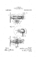
- Figure 1 is a central horizontal sectional view of my improved device, the grindingwheel spindle being shown in elevation.
- Fig, 2 is a sectional view taken on the line II-II vof Fig. 1. j
- Fig. 3 is a vertical sectional view taken on the line III-III of Fig. 1.
- the reference numeral 1 denotes the grinding-wheel carrying spindle, the same being formed toward that end nearest the' grinding-wheel 2 into slightly conical shape, as indicated at 3, and having a conical collar 4 formed thereon, as shown.
- said spindle Near its other end said spindle is threaded at 5, and at its reduced outerV end receives a grooved driving pulley 6, which is locked on said spindle by means of a setscrew 7.
- Mounted on the spindle 1 at the pulley end is an inside cone-bearing 8, upon the exterior o-f which is mounted a bushing 9.
- a bushing 10 adapted to lit the coned portion 3 and conical collar 4, as shown, said parts being retained in position vby the dust-cap 11.
- the cone-'bearing 8 and its bushing 9 are retained in position by a nut 12, in screwthreaded engagement with the screwthreaded portion 5 of the spindle, said nut being locked in position by means o f the setscrew 13, and the parts at this end being SGHAGHAT,”
- the vgrindlng-wheel 2 is iiXed in position in the spindle 3 by the frictional engagement therein of the shank 15 of the grinding-j The spindle 3 and itswheell carrier 16.
- the casing 17 is provided withan integral offset portion 18 at one side, which is best seen in detail in Fig. 3, and which is centrally apertured to recelve freely movable therein thehub 19 of an adjusting'nut 20, the latter being apertured and internally screw-threaded to re-
- the T-head 24 is inserted linto the toolv l post slot, and is clamped in position by screwing down the adjusting nut 22 ina manner readily understood.
Landscapes
- Engineering & Computer Science (AREA)
- Mechanical Engineering (AREA)
- Constituent Portions Of Griding Lathes, Driving, Sensing And Control (AREA)
Description
A. SCHAICHAT.
BENCH LATHE GmNDlNG MACHINE APPLICATION 'FILED DEC. I` 1916.
aum/Mug l Patented Aug. 14, 1917.
sTAnsfrATENT- OFFICE ABRAHAM SCHACHAT, BROOKLYN, NEW `YORK, A SSIG-NO'R TOY SLOCUM, AVRAIVI 32: SLOCUM, LABORATORIES, INC., OF NEW YORK, N.v Y., A'CORPORATIONIOF 'NEW YORK.
minorr-Ln'rn1: GRINnine-liraGrunn. I
To all whom t may concern.'
Be it known that I, ABRAHAM y a citizen of the United States, residing at Brooklyn, in the county of Kings and State y of New York, have invented certain new and useful Improvements Grinding-Machines, of which the following is a specification.
My invention relates to grinding machines, adapted more particularly for use in connection with bench-lathes, and has for its objects, first, to provide certain impro-vements in the construction of the mechanism for attaching the device to a bench-lathe and for adjusting the grinding-wheel; and, secondly, to provide certain improvements in the mounting of the spindle of the grinding-wheel.
These objects I accomplish in the manner. and by the means hereinafter described and claimed, reference being had to the accompanying drawing, in which Figure 1 is a central horizontal sectional view of my improved device, the grindingwheel spindle being shown in elevation.
Fig, 2 is a sectional view taken on the line II-II vof Fig. 1. j
Fig. 3 is a vertical sectional view taken on the line III-III of Fig. 1.
Similar numerals of reference denote corresponding parts in the several views.
-In the said drawing, the reference numeral 1 denotes the grinding-wheel carrying spindle, the same being formed toward that end nearest the' grinding-wheel 2 into slightly conical shape, as indicated at 3, and having a conical collar 4 formed thereon, as shown. Near its other end said spindle is threaded at 5, and at its reduced outerV end receives a grooved driving pulley 6, which is locked on said spindle by means of a setscrew 7. Mounted on the spindle 1 at the pulley end is an inside cone-bearing 8, upon the exterior o-f which is mounted a bushing 9. At the grinding-wheel end of said spindle ismounted a bushing 10, adapted to lit the coned portion 3 and conical collar 4, as shown, said parts being retained in position vby the dust-cap 11. At the other end the cone-'bearing 8 and its bushing 9 are retained in position by a nut 12, in screwthreaded engagement with the screwthreaded portion 5 of the spindle, said nut being locked in position by means o f the setscrew 13, and the parts at this end being SGHAGHAT,"
in Bench -Lathe Specicaton of Letter-s Patent., Patented ug,I ,14,191.7 Application filled December 1, yS/erial111:9, f i ly i covered'by aremovable vdustcap 14 similar y,
to the `dustcap 11art the opposite end. The vgrindlng-wheel 2 is iiXed in position in the spindle 3 by the frictional engagement therein of the shank 15 of the grinding-j The spindle 3 and itswheell carrier 16.
cone-bearings and other parts are all inclosed in a casing. 17, upon the reduced end portions of which thedust- caps 11 and 14 are fitted, as shown. A
In order tor pro-vide for attaching the device to a bench-lathe, the casing 17 is provided withan integral offset portion 18 at one side, which is best seen in detail in Fig. 3, and which is centrally apertured to recelve freely movable therein thehub 19 of an adjusting'nut 20, the latter being apertured and internally screw-threaded to re- The T-head 24 is inserted linto the toolv l post slot, and is clamped in position by screwing down the adjusting nut 22 ina manner readily understood. In order to adjust the casing 17 vertically, and thereby adjust the grinding-wheel 2 to the work, the upper nut 25 will be loosened, and the lower nut 20v adjusted upon the nut 22 vertically to bring the casing 17 to the desired Vposition, whereupon the parts may be clamped by screwing down the upper nut 25, as readily will be' understood i Having thus described my invention, what I claim as new and desire to secure by Letters Patent, is
,1. In a grinding machine, the combination with the casing thereof, of a-common means carried by said casing for clamping it to a bench lathe and for adjusting saidcasing toward and from its point of support in said and a common means operatingin connection 'with said nut and hub' for clamping said casing to a bench latheand for adjustjing said casing toward and from its point of support on said bench lathe.
3. In a grinding machine7 the combination with the casing thereof, of an adj ustng nut having a hub engaging said casing, a clamping .nut in screw-threaded engagement with the interior of said adjusting nut', a screw bolt passing freely through -sad clamping nut and headed at its lower end,
and a lock nut in soreW-threaded engage- Gopes of this patent may 'be obtained for ment with said screw bolt at its upper end and operating in conjunction with said adjusting nut to clamp vthe casing therebetween7 said clamping nut operating in conjunction with the headed end of said screw bolt to clamp r4Lhe device to a bench lathe.
In testimony whereof, I hereunto Set my handthis day 29th of November, 1916.
ABRAHAM SCHACHAT.
five cents each, by addressing the Commissioner of Patents, Washington, D. C.
Priority Applications (1)
| Application Number | Priority Date | Filing Date | Title |
|---|---|---|---|
| US13441016A US1237254A (en) | 1916-12-01 | 1916-12-01 | Bench-lathe grinding-machine. |
Applications Claiming Priority (1)
| Application Number | Priority Date | Filing Date | Title |
|---|---|---|---|
| US13441016A US1237254A (en) | 1916-12-01 | 1916-12-01 | Bench-lathe grinding-machine. |
Publications (1)
| Publication Number | Publication Date |
|---|---|
| US1237254A true US1237254A (en) | 1917-08-14 |
Family
ID=3305073
Family Applications (1)
| Application Number | Title | Priority Date | Filing Date |
|---|---|---|---|
| US13441016A Expired - Lifetime US1237254A (en) | 1916-12-01 | 1916-12-01 | Bench-lathe grinding-machine. |
Country Status (1)
| Country | Link |
|---|---|
| US (1) | US1237254A (en) |
-
1916
- 1916-12-01 US US13441016A patent/US1237254A/en not_active Expired - Lifetime
Similar Documents
| Publication | Publication Date | Title |
|---|---|---|
| US1237254A (en) | Bench-lathe grinding-machine. | |
| US526571A (en) | Henry j | |
| US1483748A (en) | Grinding machine | |
| US983993A (en) | Machine for sharpening taps and dies. | |
| US925016A (en) | Gem cutting and polishing machine. | |
| US1260080A (en) | Cylinder-grinder. | |
| US1240528A (en) | Device for truing wheels. | |
| US112838A (en) | Improvement in machines for grinding saw-teeth | |
| US1275208A (en) | Tool-support for grinders. | |
| US978851A (en) | Twist-drill-grinding jig. | |
| US720912A (en) | Flat-surface grinding-machine. | |
| US299433A (en) | Ca-aijcx | |
| US632666A (en) | Commutator-grinding rig. | |
| US1463033A (en) | Truing device for grinding disks | |
| US763642A (en) | Machine for facing valves or other like purposes. | |
| US1877546A (en) | Grinding machine | |
| US1018525A (en) | Tool-holding means. | |
| US647578A (en) | Operating mechanism for grindstones. | |
| US687533A (en) | Chuck or work-holder. | |
| US1256185A (en) | Valve-grinding machine. | |
| US1236604A (en) | Grinding-machine. | |
| US387874A (en) | Grinding machine | |
| US355829A (en) | lindstrom | |
| US1293048A (en) | Grinding-machine. | |
| US721400A (en) | Grinding-machine. |