US1237219A - Fluid-translating device. - Google Patents
Fluid-translating device. Download PDFInfo
- Publication number
- US1237219A US1237219A US86163714A US1914861637A US1237219A US 1237219 A US1237219 A US 1237219A US 86163714 A US86163714 A US 86163714A US 1914861637 A US1914861637 A US 1914861637A US 1237219 A US1237219 A US 1237219A
- Authority
- US
- United States
- Prior art keywords
- fluid
- chamber
- stationary
- motive
- nozzles
- Prior art date
- Legal status (The legal status is an assumption and is not a legal conclusion. Google has not performed a legal analysis and makes no representation as to the accuracy of the status listed.)
- Expired - Lifetime
Links
Images
Classifications
-
- F—MECHANICAL ENGINEERING; LIGHTING; HEATING; WEAPONS; BLASTING
- F04—POSITIVE - DISPLACEMENT MACHINES FOR LIQUIDS; PUMPS FOR LIQUIDS OR ELASTIC FLUIDS
- F04F—PUMPING OF FLUID BY DIRECT CONTACT OF ANOTHER FLUID OR BY USING INERTIA OF FLUID TO BE PUMPED; SIPHONS
- F04F5/00—Jet pumps, i.e. devices in which flow is induced by pressure drop caused by velocity of another fluid flow
- F04F5/42—Jet pumps, i.e. devices in which flow is induced by pressure drop caused by velocity of another fluid flow characterised by the input flow of inducing fluid medium being radial or tangential to output flow
Definitions
- This invention relates to fluid translating devices, and particularly to devices employing the kineticor velocity energy of the motive fluid in. exhausting'fluid from a receptacle to be evacuated, or in compressing fluid from a region of lower to a region of higher pressure.
- An object of the invention is to produce a fluid translating device, of the kinetic type, in which means are employed for maintaining the operation of the device substantially constant for practically all varying conditions.
- a furtherobject of the invention is to produce a fluid'translating device, of the kinetic type, in which a more stable and more eiiicient means than a diffuser tube is employed for converting the kinetic energy of the impelling fluid into potential energy;
- a further object is to produce a fluidv translating or ejecting device of greater capacity for a given size and weight than ejectors or similar devices now in use or known tome.
- Fig. 2 is a diagrammatic transverse sectional view of the apparatus shown in Fig. 1:
- Fig. 3 is a diagrammatic view em loyed in connection with a mathematical Cllemom stration, which is included in the applica tion.
- the apparatusfillustrated as an embodiment of my invention includes means for" discharging impelling fluid at a high ve Specification of Letters Iatent, Application filed September 14, 1914. Serial No. 861,637. 7
- annular series of nozzles 4 which discharge fluid in substan tially tangential streams into a velocity conversion or vortex chamber 5, in which the pressure of the fluid is and from which the fluid is discharged at a pressure above that at which it' enters the chamber.
- the mixture of impelling and impelled fluid or medium in traversing the chamber 5 moves, by reason of the rotary motion imparted to'it by the cooperating nozzles 4, in a spiral path and is gradually compressed by the centrifugal force occasioned by the rotary motion and.
- all the parts employed are stationary parts; they do not require adjustment for varying rates of flow orfor varying conditions of discharge or inlet pressure, and the apparatus I is capable of maintainin constant work of compression so long as t evelocity of entrance into the vortex remains constant.
- the apparatus illustrated includes a casing 7, provided with a port 8 adapted to communicate with a chamber to be exhausted or evacuated, and a port 9 through which impelling or motive fluid under pressure is delivered to the tangentially arranged nozzles 4.
- the nozzles 4 are arranged intwo groups and are located on opposite sides of the inlet to the vortex chamber 5, which is included within the casing 7 and which communicates at its inlet end with a space 11 in open communi-
- Each group of nozzles 4: is inclined inwardly so that one group cooperates with the other in discharging an annular or disk-shape stream of motive fluid through the inlet of, and into the vortex chamber 5.
- the nozzles 4 are divergent and are preferably so proportioned as to expand the motive fluid delivered to them to substantially the pressure existing at the port 8.
- the vortex is preferably, althoughnot necessarily concentric; that is, the inner peripheries of its wallsare concentric with the outer periph-
- a bypass 13 which places both sides of the chamber 11 in direct communication with the port 8. While this is not essential,
- the apparatus also includes a group of azcelerating nozzles 14; which, like the nozzles at, are tangentially disposed with relation to each other and are adapted to receive. fluid under pressure I through a port 15 and to expand the fluid to substantially the pressure normally existin in the chamber 11.
- These nozzles are located in alinement with the chamber 5 and are adapted .to discharge the motive fluid issuing from them into the chamber 5 after it has passed through a combining chamber located between the two groups of nozzles 4.
- the operation of the apparatus is as folt lows: Motive fluid delivered to the nozzles 14 is expanded in traversing these nozzles to substantially the pressure existing in the chamber 11-, .and is discharged at a high velocity into and through a portion of the chamber 11 or into an annular combining passage surrounding the nozzles 14 and 10- c1. 1d between the two groups of nozzles 4.
- the motive fluid so discharged entrains fluid to be expelled from the chamber 11 and partly compressing this fluid delivers it to the vortex chamber 5.
- fluid issuing from the nozzles 14 may occasion more or less preliminary compression of the entrained fluid, but the arrangement will preferably be such that the motive fluid discharged from the nozzles is hi hly effective as an entraining agent for the uid to be expelled and. delivers the fluid to be expelled partially comtpr'essed, but at a relatively high velocity, to the expelling nozzles 4.
- the nozzles 14: and the combining passage, shown in the draw'mgs as surrounding the nozzles 14 and located between the two groups of nozzles 4, may be so designed that the combined motive fluid and the entrained fluid medium are practically brought to rest during the process of preliminary compression and are delivered to the nozzles 4 with practically no velocity.
- the nozzles 4 expand the motive fluid traversing them to substantially the pressure existing at the inlet to the vortex ChZIIQiFZeI 5, and deliver I of the fluid medium contained within the, chamber 11, as it passes through the annular combining passage located between the two groups of-nozzles, the velocity energy oi the fluid discharged from the nozzles 14 preferably such as to assist the pressure conversion whlch takes place within the chamher 5.
- An apparatus of the character described comprising a chamber communicating with a source of medium to be compressed, stationary means for delivering a jet of impelling medium through a portion of the chamber, and stationary means for effecting a centrifugal compression of the combined media issuing from said chamber.
- An apparatus of the character described comprising a chamber having a port for delivering medium to be compressed and communicating Withan outlet through which compressed medium is discharged, stationary means for delivering a whirling jet ofimpelling mediumthrough a portion of said chamber, and a stationary free expansion chamber between said first-mentioned chamber and said outlet, through which the combined media from the first chamber pass.
- a chamber fromwhich medium is to be expelled stationary means for delivering a stream of fluid having rotary motion, in combination with.
- stationary means for delivering a stream of fluid having rotary motion in combination with.
- a chamber from which fluid is to be expelled stationary nozzles for discharging a substantially disk-shaped jet of whirling fluid-through a portion of said chamber, in combination with a substantially concentric stationary combining chamber, a stationary concentric vortex chamber, and a concentric 6.
- a chamber communicating with a source of fluid medium to be expelled, stationary fluid delivery means for expanding motive fluid to substantially the pressure existing in said chamber and for delivering thefluid so expanded into and through said chamber in a disk shaped jet,- stationary means communicating with said chamber receiving the disk-shaped jet of motive fluid and the fluid medium entrained thereby for effecting a conversion of the kinetic energy of the fluid media. passing therethrough into potential energy as represented by an increase in pressure, a collecting chamber communicating with the outlet said last mentioned means, and means for delivering expansive motive fluid to said fluid delivery means.
- An apparatus of the character described comprlsing' a chamber, communicating with a source of medium to be compressed, stationar means'for delivering a disk-shaped jet 0 expansive impelli-ng fluid through aportionof the chamber, and sta tionary means for eflecting a centrifugal compression of the combined media and issuing from said chamber.
- Appatusi of the character de scribed comprising a chamber having an inlet port for delivering medium to be compressed to the chamber, means for expand. ing motive fluid and for delivering it in a disk-shaped jet to and through a portion of naenaie chamber for expanding motive fluid and for,
- An air ejector comprising a chamber having an air inlet port, a conduit for delivermg steam to said ejector, stationary means within the chamber and communicating with'said conduit for expanding steam issuing from the conduit and for delivering. it at a high velocity and in the form of a disk-shaped jet into and through a portion of said chamber, and stationary means for efl'ecting a centrifugal compression of the steam and entrain (1 air issuing from. the chamber.
- An ejector comprising a receiving chamber communicatingwith a source of fluid medium to be ejected, motive fluid delivery means located withinjthe receiv ng chamber and gradually increasingin area from the throat to the outlet thereof for expanding motive fluid to substantially the pressure of the fluid medium within said,
- An ejector comprising a receiving Y chamber, having an inlet port for fluid to be ejected, an annular free expansion chamber communicating with saidereceiving cham ber, stationary means for delivering a substantially disk-shaped jetof expansive motive fluid into and through said free-expansion chamber, and means for delivering an auxiliary jet of motive fluid through said receiving chamber and into said free expansion, chamber,
- An ejector comprising a receiving chamber, having an inlet port for fluid to be ejected, an annular free expansion chamber communicating therewith, a, volute chamber'communicating with said free expansion chamber, means for delivering a disk shaped jetof expansive motive fluid into and through said free expansion cham her, and means for delivering an auxiliary disk-shaped jet of expansive motive fluid through said receiving chamber and into and through said free expansion chamber.
- An ejector comprising a receiving chamber, having an inlet port for fluid to be ejected, an annular vortex chamber communicating with the receiving chamber, a volute chamber communicating with the I vortex chamber, expansion nozzles for delivering a main and an auxiliary diskshaped jet of motive fluid into and through said vortex chamber.
- An ejector comprising a receiving chamber communicating with a source of fluid to be exhausted, an annular series of stationary nozzles for expanding motive fluid to substantially the pressure existing in said chamberand for delivering the fluid nun.
- expansive motive fluid-into andthroughsaid chamber for expanding motive fluid to substationary volute chamber communicating with said means and having a discharge port formed therein and means for deliver-v mg expansive motive fluid .to said nozzles.
- An ejector comprising a chamber from which expansive fluid is to beejected, an
- An ejector comprising a chamber trally within said chamber for discharging a disk-shaped jet of impelling fluid throughsaid chamber and into and through said from which fluid is to be ejected, an annular passage communicating with.
- ejector comprising. chamber from which fluid is to be. expelled, an annular passage in open and free commun cation with said chamber, a collecting chamand free communication with said passage,
- 1- expansionno zzles located ono ppos1tesides of saidpassage at the chamber side thereof j for delivering a whirlingdisk-shapedjetof Y fluid tosaid nozzle and to delivery means' assage, and an annular series of nozzles ocated within said chamber for delivering a whirling jet of expansive motive fluid through said chamber and into and through said passage.
- An e ector comprising a receiving chamber adapted; to communicate with a.
- An ejector comprisinga chaniber have ing an inlet port through which fluid to be ejected is deliveredv .to the chamber, stationary means located within the chamber tionary' means communicating with said chamber for receiving said jet and for ef- 23:1n an apparatus offluid delivery nozzle for expanding motive .fluid and for delivering the fluid so exfluid medium issuing. from said combining passage" to further compression, comprising stationary motive fluid dellvery means for expanding motive fluid and for delivering the fluid so expandedat a'high velocity and fecting a conversion of the klnetic energy of the fluid into" potential energy as represented by an increase in ressure, and a stationary collecting chain r communicating with said receiving means.
- means'for effecting a preliminary compression of fluid medium to be expelled comprising a combining passage in open communication with a source of. fluid "mediumto be expelled,. and at least one motive in the form of a disk-shaped jet, stationary means surrounding said fluid-delivery means and 'in open communication with saldpassage for receiving the dlsk-shaped jet of motive fluid and the fluid entrained v thereby and for eflectinga conversion of the Velocity energy .of the combined fluid passing therethrough into potential energy as represented by an increase in pressure,
- means for effecting a preliminary compression offluid medium-to be expelled comprising a combining passage in open said passage, in combination with means for compressing the mixture of fluid medium and motive fluid ssuing from said passage,
- stationary motive fluid delivery means gradually increasing in area from the communication with a source of fluid me throat to the outlet thereof for expanding motive fluid and for delivering the fluid so expanded at a high velocity and in the form of a dislnshaped jet
- annular passage having stationary walls receiving the diskshaped' jet of motive fluid and the fluid entrained thereby for eflecting a velocity conversion ofthe fluid passing therethrough
- annular collecting chamber having a discharge port, communicating with the outiet of said annular passage and receiving the fluid discharged therefrom, and means for delivering expansive motive fluid to said nozzle and to said motive fluid delivery means.
- stationary means in open and free communication with said chamber for receiving the disk shaped jet of fluid and fluid entrained thereby and :tor effecting a conversion of velocity energy of the fluid mixture into potential energy as represented by an increase in pressure, and a collecting chamber surrounding and communicating with said last mentioned means and having an exhaust port formed therein; in combination with a series of divergent motive flu1d delivery nozzles v for sub ecting the fluid to be expelled to the entraining action of motive fluid before it is subjected to the entraining actionoif the motive fluid delivered from said first mentioned means.
- a chamber from which. fluid is to be expelled, a'series of motive fluid delivery nozzles for expanding motive fluid and for delivering it at a high velocity into said chamber, in combination with stationary means for expanding motive fluid to sub stantially the pressure oi the mixture oi entralned fluid and fluid lssumg from said nozzles and for deliverlng the fluid so expand ed in a substantially disk shaped whirling jet, stationary means for receiving the whirling jet-and the fluid entrained thereby and for effecting a centrifugal conversion of the fluid passing therethrough and a stationary collecting chamber surrounding and communicating with said last mentioned means, and having an exhaust port.
- a chamber from which fluid is to be ejected stationary means located within said chamber for .expandingmotive fluid to substantially the pressure existing within said chamber and for delivering it in-a substantially dish shaped jet, stationary means in open and :tree communication with said chamber for receiving the disk shaped jet of fluid and fluid entrained thereby and for effecting a conversion of velocity energy of the fluid into potential energy as represented by an increase in pressure, and a collecting chamber surrounding and communicating with said last mentioned'means and provided with an exhaust port; in combination with fluid is to be ejected, a stationary annular.
- a chamber from which fluid is to be ejected an annular passage communicating with said chamber, a volute chamber surrounding and communicating with said passage, a set of motive fluid de- 'livery nozzles located on'each side of the a a a u I.
- means for finally compressing the fluid medium entrained by the, motive fluid compression offluid medium to be expelled comprising a combining passage in open communication with a source of fluid medium to be expelled, motive fluid deliverymeans gradually increasing in area from the throat to the outlet thereof for expanding motive fluid to substantially the pressure of the fluid medium at the'inlet to said passage and. for discharging the fluid so expanded in combinadelivered from said first mentioned means,
- panding motive fluid to substantially the pressure existing atthe outlet of said comand for discharging the fluid at a high velocity and in .the form of a disk-shaped jet, stationary means surrounding said last mentioned fluid delivery.
- I 35 means and in open andfree communication With said'combining passage for receiving the disk-shaped jet of motive fluid" and ⁇ fluid medium entrained thereby and for subscribed my name this 21st day of August, f 1914;
Landscapes
- Engineering & Computer Science (AREA)
- Physics & Mathematics (AREA)
- Fluid Mechanics (AREA)
- Mechanical Engineering (AREA)
- General Engineering & Computer Science (AREA)
- Jet Pumps And Other Pumps (AREA)
Description
H. F. SC HMIDT.
FLUID TRANSLATING DEVICE.
APPLICATION FILED SEPT-14, 1914.
1,287,219, Patented Aug. 14, 1917.
IN VEN TOR.
HIS ATTORNEY IN FACT I snares raa nnr m re.
Hanna r. SCHMIDT, or rrrrsnunen, rnnnsvnvanm; assrenon TO THE wrist-rinsrouse nnnc'rrac &YIVIANUFAGTURING COMPANY, A oonronnrron or PENNSYL- VANIA.
To all whom it may concern L Be it a citizen of the United States, and a resident of Pittsburgh, in the county 'of Allegheny and State of Pennsylvania, have made a new and useful Invention in Fluid- Translating Devices, of which the follow- ,v
ing is a specification. f
This invention relates to fluid translating devices, and particularly to devices employing the kineticor velocity energy of the motive fluid in. exhausting'fluid from a receptacle to be evacuated, or in compressing fluid from a region of lower to a region of higher pressure.
An object of the invention is to produce a fluid translating device, of the kinetic type, in which means are employed for maintaining the operation of the device substantially constant for practically all varying conditions.
A furtherobject of the invention is to produce a fluid'translating device, of the kinetic type, in which a more stable and more eiiicient means than a diffuser tube is employed for converting the kinetic energy of the impelling fluid into potential energy;
A further object is to produce a fluidv translating or ejecting device of greater capacity for a given size and weight than ejectors or similar devices now in use or known tome.
These and other objects are attained by apparatus embodying the features herein described and illustrated in the drawing accompanying and forming 'a part of this] application.
In the drawing:
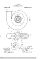
Figure 1 is a diagrammatic vertical sec-= tional view of a device embodying my invention: v U
Fig. 2 is a diagrammatic transverse sectional view of the apparatus shown in Fig. 1: and
Fig. 3 is a diagrammatic view em loyed in connection with a mathematical Cllemom stration, which is included in the applica tion.
The apparatusfillustrated as an embodiment of my invention includes means for" discharging impelling fluid at a high ve Specification of Letters Iatent, Application filed September 14, 1914. Serial No. 861,637. 7
version chamber,
,ener
- Patented Aug. 1d, 1191?.
nca ana a a. the tannin diskknown'that I, HENRY F. SCHMIDT,
crease in pressure. This velocity' conversion 1SY3JCCQI11Pl1Sh8d, 1I1 fl1e specific form of apparatus illustrated, by means of the centrifugal force'occasioned by. the rotary motionof the fluid. i
In theillustrated embodiment of themvention an annular series of nozzles 4 is provided, which discharge fluid in substan tially tangential streams into a velocity conversion or vortex chamber 5, in which the pressure of the fluid is and from which the fluid is discharged at a pressure above that at which it' enters the chamber. The annular nozzles l'discharge.
fluid, employed as the impelling medium in ejecting or compressing a fluid from aregion of lower to a region of higher pressure, and this fluid consequently entrains and imparts velocity to the fluid to be ejected or compressed. The mixture of impelling and impelled fluid or medium in traversing the chamber 5 moves, by reason of the rotary motion imparted to'it by the cooperating nozzles 4, in a spiral path and is gradually compressed by the centrifugal force occasioned by the rotary motion and. finally,
. shaped jet into andljthrough a velocitycon- I in which the velocity or kinetic energy oflthe fluid is converted into potential ,energyas represented by an in gradually built up overcoming the external pressure, leaves the chamber 5 practically devoid, of kinetic With an'apparatus operating in this manner there is no tendency towardupsetting, by which I mean a breaking .down of the pressure at the discharge or. outlet of the vortex to that at the inlet, or-fiuctuations of pressure within the vortex, due to causes other than changes in the rate of fluid or medium delivered. In addition to this, all the parts employed are stationary parts; they do not require adjustment for varying rates of flow orfor varying conditions of discharge or inlet pressure, and the apparatus I is capable of maintainin constant work of compression so long as t evelocity of entrance into the vortex remains constant.
The following mathematical demonstration. setsi orth the action which takes place sion in foot-pounds will be where a, is the velocity of entrance to the vortex. Substituting the value of p.
. 2 p (M 1) "9 1 I and integrating between the limits 7), and
p and 1'=R,, andr= c which shows that for a 100 per cent conversion efliciency the vortex must be of infinite diameter. For any given radius of vortex R the work done by the velocity-conver- 2 R1 -W= |:1-( r 2g R orthe velocity conversion efliciency is my (R;
Now the reason for the statement that the pressure remains constant in an ejector having a free vortex will be evident from the preceding mathematical demonstration, since itcfollows that as the pressure created inthe vortex is due to the centrifugal force acting on the fluid in the vortex, neglecting friction and eddies, the pressure created must be independent of the volume delivered.- This must be true for the further reason that the volume delivered does not enter into the mathematical analysis as a function of the work done, whereas, in the mathematicaldeduction of the equation of flow (or work done) in a diffusion tube, the volume enters the equation in the expression (V V As previously stated, neglecting friction, the energy transformation taking place in a free vortex remains constant regardless of .the volume delivered, even though the delivery is reduced to zero, and likewise the efficiency is for the same reasons constant, independent of the volume delivered. This explains the much higher efficiency, which may be obtained in the free vortex ejector cation with the port 8.
' cries of its walls.
at partial rating than is obtained in an ejector fitted with a difi'usion tube. Further, when the element of friction is considered, the free vortex ejector has a considerable ad vantage over the difiusion'tube ejectorbecause the surface exposed to friction is very much smaller in proportion to the capacity.
Referring now to the drawing:
The apparatus illustrated .includes a casing 7, provided with a port 8 adapted to communicate with a chamber to be exhausted or evacuated, and a port 9 through which impelling or motive fluid under pressure is delivered to the tangentially arranged nozzles 4. The nozzles 4:, as shown, are arranged intwo groups and are located on opposite sides of the inlet to the vortex chamber 5, which is included within the casing 7 and which communicates at its inlet end with a space 11 in open communi- Each group of nozzles 4: is inclined inwardly so that one group cooperates with the other in discharging an annular or disk-shape stream of motive fluid through the inlet of, and into the vortex chamber 5. The nozzles 4 are divergent and are preferably so proportioned as to expand the motive fluid delivered to them to substantially the pressure existing at the port 8. The vortex is preferably, althoughnot necessarily concentric; that is, the inner peripheries of its wallsare concentric with the outer periph- A pressure chamber 12, which is shown in the drawing as a volute chamber, communicates with the. outlet of the vortex and is provided with a delivery or discharge port 13. In the drawing I have shown a bypass 13 which places both sides of the chamber 11 in direct communication with the port 8. While this is not essential,
it' improves the operation of the apparatus by rendering the two groups of nozzles 4 equally eifective. The apparatus also includes a group of azcelerating nozzles 14; which, like the nozzles at, are tangentially disposed with relation to each other and are adapted to receive. fluid under pressure I through a port 15 and to expand the fluid to substantially the pressure normally existin in the chamber 11. These nozzles are located in alinement with the chamber 5 and are adapted .to discharge the motive fluid issuing from them into the chamber 5 after it has passed through a combining chamber located between the two groups of nozzles 4.
The operation of the apparatus is as folt lows: Motive fluid delivered to the nozzles 14 is expanded in traversing these nozzles to substantially the pressure existing in the chamber 11-, .and is discharged at a high velocity into and through a portion of the chamber 11 or into an annular combining passage surrounding the nozzles 14 and 10- c1. 1d between the two groups of nozzles 4.
The motive fluid so discharged entrains fluid to be expelled from the chamber 11 and partly compressing this fluid delivers it to the vortex chamber 5. Depending upon the design of the nozzles 14 and of the annular combining passage surrounding them, fluid issuing from the nozzles 14 may occasion more or less preliminary compression of the entrained fluid, but the arrangement will preferably be such that the motive fluid discharged from the nozzles is hi hly effective as an entraining agent for the uid to be expelled and. delivers the fluid to be expelled partially comtpr'essed, but at a relatively high velocity, to the expelling nozzles 4. It will be understood by those skilled in the art that the nozzles 14: and the combining passage, shown in the draw'mgs as surrounding the nozzles 14 and located between the two groups of nozzles 4, may be so designed that the combined motive fluid and the entrained fluid medium are practically brought to rest during the process of preliminary compression and are delivered to the nozzles 4 with practically no velocity. The nozzles 4 expand the motive fluid traversing them to substantially the pressure existing at the inlet to the vortex ChZIIQiFZeI 5, and deliver I of the fluid medium contained within the, chamber 11, as it passes through the annular combining passage located between the two groups of-nozzles, the velocity energy oi the fluid discharged from the nozzles 14 preferably such as to assist the pressure conversion whlch takes place within the chamher 5.
While I have illustrated but one embodiment of my invention, it will be apparent to those skilled in the art, that the drawings are merely illustrative, and that various changes, substitutions, additions and omissions may be made in the apparatus illustrated without departing from the spirit and scope f the invention as set forth by the appended claims.
- What I claim is: I
1. In an apparatus of the character described, the combination of a chamber communicating with a source of medium to be compressed, a vortex communicating with the chamber, and stationary means for decollecting chamber.
livering a whirling jet of impelling fluid through said chamber and said vortex for entraining medium in passing through said chamber.
2. An apparatus of the character described, comprising a chamber communicating with a source of medium to be compressed, stationary means for delivering a jet of impelling medium through a portion of the chamber, and stationary means for effecting a centrifugal compression of the combined media issuing from said chamber.
3. An apparatus of the character described, comprising a chamber having a port for delivering medium to be compressed and communicating Withan outlet through which compressed medium is discharged, stationary means for delivering a whirling jet ofimpelling mediumthrough a portion of said chamber, and a stationary free expansion chamber between said first-mentioned chamber and said outlet, through which the combined media from the first chamber pass. I
4. In an apparatus of the character described, a chamber fromwhich medium is to be expelled, stationary means for delivering a stream of fluid having rotary motion, in combination with. a substantially concentric stationary combining chamber, a vortex chamber, and a collecting chamber. i
5. In an apparatus of the characterdescribed, a chamber from which fluid is to be expelled, stationary nozzles for discharging a substantially disk-shaped jet of whirling fluid-through a portion of said chamber, in combination with a substantially concentric stationary combining chamber, a stationary concentric vortex chamber, and a concentric 6. In combination in an apparatus of the character described, a chamber communicating with a source of fluid medium to be expelled, stationary fluid delivery means for expanding motive fluid to substantially the pressure existing in said chamber and for delivering thefluid so expanded into and through said chamber in a disk shaped jet,- stationary means communicating with said chamber receiving the disk-shaped jet of motive fluid and the fluid medium entrained thereby for effecting a conversion of the kinetic energy of the fluid media. passing therethrough into potential energy as represented by an increase in pressure, a collecting chamber communicating with the outlet said last mentioned means, and means for delivering expansive motive fluid to said fluid delivery means.
i. in combination in an apparatus of the ob ,racter described, a c amber co'mnninicating with a. source of fluid medium to be expolled, stationary means located within 1-,. chamber for expanding motive fluid to sub- I increase in pressure, a collecting chamber surrounding said jet receiving means, and means for delivering expansive motive fluld to said fluid expanding and discharging means;
8. An apparatus of the character described, comprlsing' a chamber, communicating with a source of medium to be compressed, stationar means'for delivering a disk-shaped jet 0 expansive impelli-ng fluid through aportionof the chamber, and sta tionary means for eflecting a centrifugal compression of the combined media and issuing from said chamber.
.flarhn "apparatusi of the character de scribed; comprising a chamber having an inlet port for delivering medium to be compressed to the chamber, means for expand. ing motive fluid and for delivering it in a disk-shaped jet to and through a portion of naenaie chamber for expanding motive fluid and for,
delivering the fluid so expanded in the form of a whirling disk shaped jet through a free space within said chamber, stationary said chamber, stationary means communieating with said chamber and receiving the fluidand the entrained medium discharged therefrom for effecting a centrifugal'compression of the fluid and mediumissuingfrom the chamber. j i
10. An air ejector, comprising a chamber having an air inlet port, a conduit for delivermg steam to said ejector, stationary means within the chamber and communicating with'said conduit for expanding steam issuing from the conduit and for delivering. it at a high velocity and in the form of a disk-shaped jet into and through a portion of said chamber, and stationary means for efl'ecting a centrifugal compression of the steam and entrain (1 air issuing from. the chamber.
'11. An ejector comprising a receiving chamber communicatingwith a source of fluid medium to be ejected, motive fluid delivery means located withinjthe receiv ng chamber and gradually increasingin area from the throat to the outlet thereof for expanding motive fluid to substantially the pressure of the fluid medium within said,
chamber and for discharging the fluid so expanded at ahigh velocity and in the form of an annular jet through a portion of said chamber, a stationary annular passage surrounding said fluid delivery means and re ceiving the annular jet of motive fluid and the fluid medium entrained thereby for effecting a conversion of the velocity energy of the combined fluid passing therethrough into potential energy as represented by an increase in pressure, a stationary collecting means communicating with the free space of said. chamber for receiving the whirling jet and the fluid entrained thereby footing a centrifugal compression of the motive and entrained fluid [passing therethrough, and a stationary volute chamber surrounding and communicating with said last mentioned means.
and for er"- 13. An ejector comprising a receiving Y chamber, having an inlet port for fluid to be ejected, an annular free expansion chamber communicating with saidereceiving cham ber, stationary means for delivering a substantially disk-shaped jetof expansive motive fluid into and through said free-expansion chamber, and means for delivering an auxiliary jet of motive fluid through said receiving chamber and into said free expansion, chamber,
1-4:; An ejector comprising a receiving chamber, having an inlet port for fluid to be ejected, an annular free expansion chamber communicating therewith, a, volute chamber'communicating with said free expansion chamber, means for delivering a disk shaped jetof expansive motive fluid into and through said free expansion cham her, and means for delivering an auxiliary disk-shaped jet of expansive motive fluid through said receiving chamber and into and through said free expansion chamber.
15. An ejector comprising a receiving chamber, having an inlet port for fluid to be ejected, an annular vortex chamber communicating with the receiving chamber, a volute chamber communicating with the I vortex chamber, expansion nozzles for delivering a main and an auxiliary diskshaped jet of motive fluid into and through said vortex chamber.
16. An ejector comprising a receiving chamber communicating with a source of fluid to be exhausted, an annular series of stationary nozzles for expanding motive fluid to substantially the pressure existing in said chamberand for delivering the fluid nun.
- centrally within saldchamber' for del1verber surroundlng ,said passage and-1n .open
expansive motive fluid-into andthroughsaid chamber for expanding motive fluid to substationary volute chamber communicating with said means and having a discharge port formed therein and means for deliver-v mg expansive motive fluid .to said nozzles.
17. An ejector comprising a chamber from which expansive fluid is to beejected, an
motive fluid into and through said passage,
1 and an annular series-of nozzles located cenpassage. '18. An ejector comprising a chamber trally within said chamber for discharging a disk-shaped jet of impelling fluid throughsaid chamber and into and through said from which fluid is to be ejected, an annular passage communicating with. said chamber,- a collecting chamber surrounding and com-- mumcating with the annular outlet port "of said passage, nozzles 'for expanding impel ling fluid andfor delivering; it in the, form of a diskshaped'jet into andthrough said passage, and meansi-locatedsubstantially ing an auxiliary disk-shaped jet of motive within saidfirst mentioned chamber for'dis-I' charging a'whirling disk-shaped jetof. expansive motive fluid into and through said fluid. into and through said passage.
"; .19. An ejectorf comprismg a chamber from which-fluid ,t'o-be ejected is expelled, v
a an annular passage communicating through- "outits length with.saidchamber,"1a collecting 'ichamber in openand-free vcom'munication' with said passagefexpansion"nozzles,
" -,motive fluid into andthroughsaid passage,
for delivering a. whirling disk-shaped jet of and means located substantially centrally passage. Y
20.7An'. ejector, comprising. chamber from which fluid is to be. expelled, an annular passage in open and free commun cation with said chamber, a collecting chamand free communication with said passage,
1- expansionno zzles located ono ppos1tesides of saidpassage at the chamber side thereof j for delivering a whirlingdisk-shapedjetof Y fluid tosaid nozzle and to delivery means' assage, and an annular series of nozzles ocated within said chamber for delivering a whirling jet of expansive motive fluid through said chamber and into and through said passage.
f '1.- An e ector comprising a receiving chamber adapted; to communicate with a.
source of fluid to be ejected, in combination with stationary means located wlthin the stan tially the normal pressure existing within the chamber and for deliverlngthe for expanding motive fluid and for deliver- 1ng 1t in a whirling diskv shaped jet, staincrease in pressure,.' and. a stationary; 001
lecting chamber communicatingwith said last mentioned means.
22.}An ejector comprisinga chaniber have ing an inlet port through which fluid to be ejected is deliveredv .to the chamber, stationary means located within the chamber tionary' means communicating with said chamber for receiving said jet and for ef- 23:1n an apparatus offluid delivery nozzle for expanding motive .fluid and for delivering the fluid so exfluid medium issuing. from said combining passage" to further compression, comprising stationary motive fluid dellvery means for expanding motive fluid and for delivering the fluid so expandedat a'high velocity and fecting a conversion of the klnetic energy of the fluid into" potential energy as represented by an increase in ressure, and a stationary collecting chain r communicating with said receiving means. j he character-de- Yscribe d, means'for effecting a preliminary compression of fluid medium to be expelled, comprising a combining passage in open communication with a source of. fluid "mediumto be expelled,. and at least one motive in the form of a disk-shaped jet, stationary means surrounding said fluid-delivery means and 'in open communication with saldpassage for receiving the dlsk-shaped jet of motive fluid and the fluid entrained v thereby and for eflectinga conversion of the Velocity energy .of the combined fluid passing therethrough into potential energy as represented by an increase in pressure,
and means for delivering expansive'motive a" stationary collecting chamber surround.- i .ing the last mentioned stationary means and .receiving the fluid discharged therefrom,
said motive fluid 24. In an apparatus of the character described, means for effecting a preliminary compression offluid medium-to be expelled, comprising a combining passage in open said passage, in combination with means for compressing the mixture of fluid medium and motive fluid ssuing from said passage,
comprising stationary motive fluid delivery means gradually increasing in area from the communication with a source of fluid me throat to the outlet thereof for expanding motive fluid and for delivering the fluid so expanded at a high velocity and in the form of a dislnshaped jet, an annular passage having stationary walls receiving the diskshaped' jet of motive fluid and the fluid entrained thereby for eflecting a velocity conversion ofthe fluid passing therethrough, and an annular collecting chamber, having a discharge port, communicating with the outiet of said annular passage and receiving the fluid discharged therefrom, and means for delivering expansive motive fluid to said nozzle and to said motive fluid delivery means.
25. in an. apparatus of the'character described, means for effecting a preliminary f compression of fluid medium to be expelled,
comprising an annular combining passage, a
series of nozzles for expanding motive fluid and for delivering it at a high velocity and in the form of 'a whirling jet into and through said" passage, in combination with means for further compressing the fluid medium entrained by said jet and the fluid of said jet, said last mentioned means comprising a stationary means for expanding motive fluid and for delivering it in the form of a whirling jet, means in open communication with said combining passage for receiving the last mentioned whirling jet and the fluid entrained therebyand for effecting a centrifugal compression of the fluid passing therethrough,and a collecting chamber receiving the fluid mixture discharged from said last mentioned means -26. In an apparatus of the character at scribed, a chamber from which fluid is to be ejected, stationary means for expanding motive fluid to substantially the pressure existin in said chamber and for delivering the uidsc expanded in a disk shaped jet,
stationary means in open and free communication with said chamber for receiving the disk shaped jet of fluid and fluid entrained thereby and :tor effecting a conversion of velocity energy of the fluid mixture into potential energy as represented by an increase in pressure, and a collecting chamber surrounding and communicating with said last mentioned means and having an exhaust port formed therein; in combination with a series of divergent motive flu1d delivery nozzles v for sub ecting the fluid to be expelled to the entraining action of motive fluid before it is subjected to the entraining actionoif the motive fluid delivered from said first mentioned means.
27. In an apparatus of the character described, a chamber from which. fluid is to be expelled, a'series of motive fluid delivery nozzles for expanding motive fluid and for delivering it at a high velocity into said chamber, in combination with stationary means for expanding motive fluid to sub stantially the pressure oi the mixture oi entralned fluid and fluid lssumg from said nozzles and for deliverlng the fluid so expand ed in a substantially disk shaped whirling jet, stationary means for receiving the whirling jet-and the fluid entrained thereby and for effecting a centrifugal conversion of the fluid passing therethrough and a stationary collecting chamber surrounding and communicating with said last mentioned means, and having an exhaust port.
28. in an apparatus of the character de scribed, a chamber from which fluid is to be ejected, stationary means located within said chamber for .expandingmotive fluid to substantially the pressure existing within said chamber and for delivering it in-a substantially dish shaped jet, stationary means in open and :tree communication with said chamber for receiving the disk shaped jet of fluid and fluid entrained thereby and for effecting a conversion of velocity energy of the fluid into potential energy as represented by an increase in pressure, and a collecting chamber surrounding and communicating with said last mentioned'means and provided with an exhaust port; in combination with fluid is to be ejected, a stationary annular.
passage communicating with said'chamber ice and radially disposed with relation to said chamber, stationary motive fluid delivery nozzles located on opposite sides of the inlet to said, annular passage and adapted to expand motive fluid and to discharge the motive fluid so expanded in the form of adisk shaped jet into and through said annular passage, a set of auxiliary nozzles lo cated within said chamber for expanding motive fluid and for delivering the expand ed fluid in a disk shapedjet between the mentioned nozzles and into said annular passage, and a collecting chamber surlet of said passage. l I
30. In combination in an apparatus of the character described, a chamber from which fluid is to be ejected, an annular passage communicating with said chamber, a volute chamber surrounding and communicating with said passage, a set of motive fluid de- 'livery nozzles located on'each side of the a a a u I. rounding and 'communlcatlng with the outj inlet to said passage and adapted to expand v into and through said passage, I tion With means for finally compressing the fluid medium entrained by the, motive fluid compression offluid medium to be expelled, comprising a combining passage in open communication with a source of fluid medium to be expelled, motive fluid deliverymeans gradually increasing in area from the throat to the outlet thereof for expanding motive fluid to substantially the pressure of the fluid medium at the'inlet to said passage and. for discharging the fluid so expanded in combinadelivered from said first mentioned means,
. and comprising stationary motive fluid delivery means gradually increasingin area I from the throat to the outlet thereof for exbining passage,
panding motive fluid to substantially the pressure existing atthe outlet of said comand for discharging the fluid at a high velocity and in .the form of a disk-shaped jet, stationary means surrounding said last mentioned fluid delivery. I 35 means and in open andfree communication With said'combining passage for receiving the disk-shaped jet of motive fluid" and} fluid medium entrained thereby and for subscribed my name this 21st day of August, f 1914; I
effecting a conversion of the velocity energy of the combined fluid and fluid' medium. passing therethrough 'into I potential energy v as represented by an increase in pressure, a stationary collecting chamber surrounding the last mentioned stationary means and repassage, and means for delivering.
ceiving the fluid discharged therefrom, and means for delivering expansive motive fluid to both of said motive fluid delivery means.
32. In an apparatus of the character described,'means for efl'ecting a preliminary compression of fluid to be expelled, comprising a combining passage havingits inlet in a source of fluid open communication with medium to be expelled, at least one divergent nozzle expanding motive fluid to substantially the pressure normally existing at the. inlet to said combining passage .and fin discharging the fluid so expanded into and through said passage, in combination With means for finally compressing the motive fluid discharged from said nozzle and the fluid mediumentrained thereby, com
' prising stationary-means for expanding mo-. tive' fluidto substantially "the pressure ex:
isting at the outlet of said combining passage, and for discharging thefluid so ex-, panded at a high velocity and in the form of a disk -shaped jet, a'st'atioiiary annular I passage in open communication with the outlet of the, combining passage for receiv-. ing-the' disk-shaped jet of motive fluid-and the fluid medium entrained thereby and for effecting a pressure conversion of the velocity-energy of the combined fluid and fluid -medium passing therethrough into potential energy as represented by an increase in pressure, a stationary collecting T chamber surrounding the stationary fluid receiving means and receiving the fluid discharged therefrom, and means for delivering expansive motive fluid to saidnozzle and to said fluid discharging means.
In testimony whereof, I have hereunto HEN Y F. SCHMIDT. Witnesses: I
Priority Applications (1)
| Application Number | Priority Date | Filing Date | Title |
|---|---|---|---|
| US86163714A US1237219A (en) | 1914-09-14 | 1914-09-14 | Fluid-translating device. |
Applications Claiming Priority (1)
| Application Number | Priority Date | Filing Date | Title |
|---|---|---|---|
| US86163714A US1237219A (en) | 1914-09-14 | 1914-09-14 | Fluid-translating device. |
Publications (1)
| Publication Number | Publication Date |
|---|---|
| US1237219A true US1237219A (en) | 1917-08-14 |
Family
ID=3305037
Family Applications (1)
| Application Number | Title | Priority Date | Filing Date |
|---|---|---|---|
| US86163714A Expired - Lifetime US1237219A (en) | 1914-09-14 | 1914-09-14 | Fluid-translating device. |
Country Status (1)
| Country | Link |
|---|---|
| US (1) | US1237219A (en) |
-
1914
- 1914-09-14 US US86163714A patent/US1237219A/en not_active Expired - Lifetime
Similar Documents
| Publication | Publication Date | Title |
|---|---|---|
| US4673335A (en) | Gas compression with hydrokinetic amplifier | |
| US3694107A (en) | Ejector apparatus and method of utilizing same | |
| US3064878A (en) | Method and apparatus for high performance evacuation system | |
| US3545886A (en) | Ejector | |
| US2641442A (en) | Turbine | |
| US1421843A (en) | Fluid-translating device | |
| US1421844A (en) | Fluid-translating device | |
| US4388045A (en) | Apparatus and method for mixing and pumping fluids | |
| US1237219A (en) | Fluid-translating device. | |
| US1449504A (en) | Method of and apparatus for compressing elastic fluids | |
| US3748054A (en) | Reaction turbine | |
| US1228608A (en) | Fluid-operated ejector. | |
| US3982848A (en) | Side channel ring compressor including a channel break decompression nozzle | |
| US20020119051A1 (en) | High efficiency steam ejector for desalination applications | |
| US1549353A (en) | Fluid-compressing apparatus | |
| US1168297A (en) | Fluid-handling mechanism. | |
| US1324236A (en) | Inghquse electric | |
| US1421842A (en) | Fluid-translating device | |
| US3031977A (en) | Gas-drive jet pump | |
| US1203841A (en) | Centrifugal air-pump. | |
| US2790595A (en) | Steam jet apparatus | |
| US4003673A (en) | Fluid pressurizer | |
| US1614574A (en) | Fluid-translating device | |
| US1555030A (en) | Fluid-translating device | |
| US1215321A (en) | Ejector. |