US1237173A - Adjustable side curtain. - Google Patents
Adjustable side curtain. Download PDFInfo
- Publication number
- US1237173A US1237173A US61116911A US1911611169A US1237173A US 1237173 A US1237173 A US 1237173A US 61116911 A US61116911 A US 61116911A US 1911611169 A US1911611169 A US 1911611169A US 1237173 A US1237173 A US 1237173A
- Authority
- US
- United States
- Prior art keywords
- curtain
- curtains
- secured
- adjustable side
- side curtain
- Prior art date
- Legal status (The legal status is an assumption and is not a legal conclusion. Google has not performed a legal analysis and makes no representation as to the accuracy of the status listed.)
- Expired - Lifetime
Links
- 238000010276 construction Methods 0.000 description 5
- 239000000463 material Substances 0.000 description 3
- 241001125879 Gobio Species 0.000 description 2
- 239000002184 metal Substances 0.000 description 2
- 230000002452 interceptive effect Effects 0.000 description 1
- QCOXCILKVHKOGO-UHFFFAOYSA-N n-(2-nitramidoethyl)nitramide Chemical compound [O-][N+](=O)NCCN[N+]([O-])=O QCOXCILKVHKOGO-UHFFFAOYSA-N 0.000 description 1
- 210000003813 thumb Anatomy 0.000 description 1
Images


Classifications
-
- B—PERFORMING OPERATIONS; TRANSPORTING
- B60—VEHICLES IN GENERAL
- B60J—WINDOWS, WINDSCREENS, NON-FIXED ROOFS, DOORS, OR SIMILAR DEVICES FOR VEHICLES; REMOVABLE EXTERNAL PROTECTIVE COVERINGS SPECIALLY ADAPTED FOR VEHICLES
- B60J1/00—Windows; Windscreens; Accessories therefor
- B60J1/08—Windows; Windscreens; Accessories therefor arranged at vehicle sides
- B60J1/085—Windows; Windscreens; Accessories therefor arranged at vehicle sides removably mounted
Definitions
- the objectof this invention is to provide in connection withreither a collapsible top or a permanent stationary top of any kind, quickly adjustable curtains adapted to close the space beneaththeatop and applied'to the sides or to the sides and ends, as preferred.
- the invention for convenience, is shown embodied in connection with a cape top of an automobile, although adaptable for use in connection with any kind of a top or canopy and for any sort of a device or ve hicle.
- Figure 1 is a view in side elevation of an automobile equipped with curtains nembodying my invention.
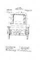
- Fig. 2 is a rear end elevation thereof.
- FIG. 3 is'a side elevation of the receptacle for the curtain, showing the same broken away.
- Fig. 4 is a broken section on line 4.-4 of Fig. 3.
- Fig. 5 is a fragmentary transverse section to illustrate the guides for the curtain, as shown installed in Fig. 1.-
- - Fig. 6 is-a transverse section of the receptacle and"curtain, showing the curtain re tracted therein.
- Fig. 7 is a fragmentary side view illusof the curtain in adjusted position.
- Figs. 9 and 10 illustrate respectively fragmentary front and side elevations of ourtains applied to the wind shields.
- the vehicle or device to which the curtain is applied indicates the vehicle or device to which the curtain is applied, in this instance (but for convenience only) shown as an automobile.
- 2. indicates the top or canopy, in this instance (though not necessarily so) shown as the ordinary cape top of an automobile securcd as usual to the body of the automobile and projecting forwardly over the front wind shield 3.
- the rear brace bow 4. for the top is connected in any suitable manner with the canvas or other covering of the top, and also with the rear end walls or strips 5. which extend around the bend of the bow and downwardly and "are secured around the back of the rear seat or to any corresponding portion of the body to which the top is attached.
- the .top is, of course, supported in upright position by means of any suitable forwardly led straps or lines 7. suitably attached to the body. in.
- casings 8 which are shown as cylindric and comprising a shell of any suitable material having alongitudinal slot in one side thereof, as shown in Fig. 6.
- the lower end of the casing, as shown, may be rounded or otherwise suitably shaped to fit in a suitable socket at the end of the top.
- Threaded or otherwise secured on the upper end of the casing is a cap 9, shaped to fit beneath the end of the top.
- An angular axle seat is provided in said cap to receive the angular end of a gudgeon 10, rotatably engaged on which is a spring impelled curtain roller 11, of a familiar or any suitable type.
- a foot-.piece 12 having a cylindric seat therein to receive the cylindric gudgeon 13, secured on the lower end of the curtain rod or pole 1-1.
- straps of metal 14 are provided on each side of said casing near the lower end thereof and provided with apertures therethrough, which are reduced or narrowed at their upper edges to engage over the heads of suitable bolts or attaching means secured in the back of the body and whereby the curtain casing is bracingly supported in upright position.
- corresponding parallel straps 15 may be secured at the upper end of the casing at any convenient point to be engaged positively on the brace bow, 4,for the top, or, if used in connection with a canopy, upon any stationary or rigid part of the construction.
- a drop curtain 16 is provided at the rear end of the top to close the space at the end' of the top between the curtain casings.
- the curtains 17, secured on the curtain rollers in the respective casings may be of any suitable'material and secured in place in any suitable manner.
- Each is of a width to extend from the top of the body 1, upwardly above the lower margin of the top, as shown in Fig. 5, and a band or strip 18, of any suitable material is secured around the top, as shown in Fig. 5, to afford between the same and the lower edge of a top a recess or groove to receive the upper edge of the curtain.
- the forward or outer end of each curtain is rigidly secured to a suitable rod 19, or to any suitable means to prevent the end of the curtain being retracted into the casing when the curtain is wound up. 1
- the rod 19 is tubular and slidably engagedtherein on each side the center are rods, each provided with a thumb piece 23, on its inner end projecting through a slot inthe tubular rod 19.
- a lining strip 25 is shown in the space between the top cover 2, and the outer facing strip 18, and openings are shown through the lining strip corresponding in position with the sockets. in the rail.
- Studs or buttons 20, of any kind also, may be secured in the bows for the top, some of which are arranged closely adjacent to the lower margin'of the top, while others are arranged but a short distance above the top of the body.
- the curtain for each side of thepar may be provided with corresponding apertures to receive the studs therein.
- the studs or buttons are arranged an equal distance apart on each of the bows and on the shield 3, thereby permitting the curtain to be adjusted to close the entire side of the car or to close merely the rear end of the bow 21, or to close the entire space to the front bow 22, as preferred.
- the upper edge of the body may be grooved, as shown in Fig. 5, if desired, to assist in holding the lower edge of the curtain inplace. This,
- the curtain may be drawn on the inner side of the bows where installed, as shown in Fig. 1, or on the inner side of the supporting columns or stanchions for a canopy top. Where so arranged, the curtains may be readily adjusted from within the car or vehicle without necessitating stopping and without interfering with the.
- top curtain casings will depend upon the structure to which the same is'to be applied.
- the construction permits'of many different arrangements, one of which is illustrated in Figs. 9 and 10, in which the wind shield 25*, is hingedly connected at the top of the dash at the rear of the hood.
- the side frame members of saidshield are tubular metal curtain casings'26, the curtains 27, of which may be drawn rearwardly and attached to any suitable part of the body of the car or to the bows by means of buttons 28, or any other suitable attaching means.
- These curtains maybe of any suitabie size or shape and may, if desired, ex-
- msmte tend down to, or below the top of the body or frontdoors, and afiord a Wind guard for the operator (or those occupying the front seats) from all lateral Winds.
Landscapes
- Engineering & Computer Science (AREA)
- Mechanical Engineering (AREA)
- Curtains And Furnishings For Windows Or Doors (AREA)
Description
v A. E. 000K. ADJU$TABLE SIDE CURTAIN.
ILED FEB. 27'
" Patented Aug. 14, 1917.
4 sh ssssssss ET].
- vqifia I A, E. 000 -ADJUSTABLE SIDE CURTAIN.
- APPLICATION FILED FEB. 2% 1911- 7 1,237,173. v PatentedA 4 .SHEE
HEET. 2-
11g. 14,1917. Ts-s A E COOK ADJUSTABLE sios' cum/am. APPLICATION FILED FEB-27. I9H- 1 ,237, 1 73 Patented Aug. 14, 1917.
4 SHEETS-SHE ET 3.
A. E. COOK. ADJUSTABLE SIDE CURTAIN.
' APPLICATION FILED FEB- 27, 1 91!- 1,237,173.
Patented Aug. 14, 19 17.
- {SHEETS-SHEET, 4.
ALBERT E. COOK, OF ODEBOLT, IOWA.
ADJUSTABLE SIDE CURTAIN.
Specification of Letters Patent.
Patented Amiga-14, 1917.
Application filed February 27, 1911. l Serial No. 611,169.
' To all whom it may concern:
' scription of the same, reference being had to the accompanying drawings, and to the numbers of reference marked thereon, which forrna part ofthis specification.
Much vinconvenience and delay is occasioned in putting on and taking off the side curtainsof automobiles equipped with cape tops, and this is-true-also of horse drawn vehicles and of, launches and other boats equipped either with a cape top or a canopy top of any kind, whether: adjustable or stationary, and with which side curtains are.-
used. This inconvenience arises in part from the fact that usually no convenient and quickly accessible place of carriage for the side curtains is provided on such vehicles orboats. In consequence, delay is occasioned in obtaining the side curtains for use 'or in stowing'the same after use, and, inasmuch as side curtains are 'usually'constructed of a number of pieces, considerable time is required in attaching the-same to' the car andv in detaching-the'saine from the car. This, in any event, occasions exasperating delay, andv in many instances, delay in attaching the side curtains eryposes the occupants. and the operator to the storm to an extent to occasion great discomfort or endanger health.
The objectof this invention is to provide in connection withreither a collapsible top or a permanent stationary top of any kind, quickly adjustable curtains adapted to close the space beneaththeatop and applied'to the sides or to the sides and ends, as preferred.
It is also an important object of the in-' vention to afford a receptacle for each cur-- tain when not in use, into which the curtain is automatically retracted and in which it p is yieldingly held until required for use.
It is also an object of'the invention to afford a construction in which the curtains may be quickly removed as a wholc,-if desired, by simply lifting the receptacle therefor from place.
The invention for convenience, is shown embodied in connection with a cape top of an automobile, although adaptable for use in connection with any kind of a top or canopy and for any sort of a device or ve hicle.
The invention embraces many novel features and consists in the matters hereinafter described and more fully pointed out and defined in the appended claim.
In the drawings:
Figure 1 is a view in side elevation of an automobile equipped with curtains nembodying my invention.
Fig. 2 is a rear end elevation thereof.
'Fig. 3 is'a side elevation of the receptacle for the curtain, showing the same broken away.
Fig. 4 is a broken section on line 4.-4 of Fig. 3.
Fig. 5 is a fragmentary transverse section to illustrate the guides for the curtain, as shown installed in Fig. 1.-
- Fig. 6 is-a transverse section of the receptacle and"curtain, showing the curtain re tracted therein.
Fig. 7 is a fragmentary side view illusof the curtain in adjusted position.
a0 v tratingthe means for engagingthe free end I Fig. ,8 is a fragmentary detail of the en-- I gaging" means shown in Fig. 7. p
Figs. 9 and 10 illustrate respectively fragmentary front and side elevations of ourtains applied to the wind shields.
As shown in the drawings:
1, indicates the vehicle or device to which the curtain is applied, in this instance (but for convenience only) shown as an automobile. 2. indicates the top or canopy, in this instance (though not necessarily so) shown as the ordinary cape top of an automobile securcd as usual to the body of the automobile and projecting forwardly over the front wind shield 3. In the cape top construction shown. the rear brace bow 4. for the top, is connected in any suitable manner with the canvas or other covering of the top, and also with the rear end walls or strips 5. which extend around the bend of the bow and downwardly and "are secured around the back of the rear seat or to any corresponding portion of the body to which the top is attached. The .top is, of course, supported in upright position by means of any suitable forwardly led straps or lines 7. suitably attached to the body. in.
ncath the rear end of the top, and on each.
side of the center are casings 8, which are shown as cylindric and comprising a shell of any suitable material having alongitudinal slot in one side thereof, as shown in Fig. 6. The lower end of the casing, as shown, may be rounded or otherwise suitably shaped to fit in a suitable socket at the end of the top.
Threaded or otherwise secured on the upper end of the casing, is a cap 9, shaped to fit beneath the end of the top. An angular axle seat is provided in said cap to receive the angular end of a gudgeon 10, rotatably engaged on which is a spring impelled curtain roller 11, of a familiar or any suitable type. In the lower end of the casing is secured a foot-.piece 12, having a cylindric seat therein to receive the cylindric gudgeon 13, secured on the lower end of the curtain rod or pole 1-1.
As shown, straps of metal 14, are provided on each side of said casing near the lower end thereof and provided with apertures therethrough, which are reduced or narrowed at their upper edges to engage over the heads of suitable bolts or attaching means secured in the back of the body and whereby the curtain casing is bracingly supported in upright position. If desired, corresponding parallel straps 15, may be secured at the upper end of the casing at any convenient point to be engaged positively on the brace bow, 4,for the top, or, if used in connection with a canopy, upon any stationary or rigid part of the construction. As shown, a drop curtain 16, is provided at the rear end of the top to close the space at the end' of the top between the curtain casings.
The curtains 17, secured on the curtain rollers in the respective casings, may be of any suitable'material and secured in place in any suitable manner. Each is of a width to extend from the top of the body 1, upwardly above the lower margin of the top, as shown in Fig. 5, and a band or strip 18, of any suitable material is secured around the top, as shown in Fig. 5, to afford between the same and the lower edge of a top a recess or groove to receive the upper edge of the curtain. The forward or outer end of each curtain is rigidly secured to a suitable rod 19, or to any suitable means to prevent the end of the curtain being retracted into the casing when the curtain is wound up. 1
As shown, the rod 19, is tubular and slidably engagedtherein on each side the center are rods, each provided with a thumb piece 23, on its inner end projecting through a slot inthe tubular rod 19. A spring 24,
- bears against the adjacent end of said rods in said tube and acts to hold the rods extended with their oppositely directed ends projected beyond the ends of the tubular asagna rod 19, and in position to engage in sockets in the rail of the body and also in recesses in the guide groove in the top of, canopy.- In the drawings, a lining strip 25, is shown in the space between the top cover 2, and the outer facing strip 18, and openings are shown through the lining strip corresponding in position with the sockets. in the rail.
Studs or buttons 20, of any kind also, may be secured in the bows for the top, some of which are arranged closely adjacent to the lower margin'of the top, while others are arranged but a short distance above the top of the body.
The curtain for each side of thepar may be provided with corresponding apertures to receive the studs therein. The studs or buttons are arranged an equal distance apart on each of the bows and on the shield 3, thereby permitting the curtain to be adjusted to close the entire side of the car or to close merely the rear end of the bow 21, or to close the entire space to the front bow 22, as preferred. Of course, the upper edge of the body may be grooved, as shown in Fig. 5, if desired, to assist in holding the lower edge of the curtain inplace. This,
however, is not essential. Of course, if preferred, the curtain may be drawn on the inner side of the bows where installed, as shown in Fig. 1, or on the inner side of the supporting columns or stanchions for a canopy top. Where so arranged, the curtains may be readily adjusted from within the car or vehicle without necessitating stopping and without interfering with the.
convenience of the operator or passengers. While I have shown the device installed in'connection with a cape top, it is to be understood. that the particlar type of top curtain casings will depend upon the structure to which the same is'to be applied. The construction permits'of many different arrangements, one of which is illustrated in Figs. 9 and 10, in which the wind shield 25*, is hingedly connected at the top of the dash at the rear of the hood. The side frame members of saidshield are tubular metal curtain casings'26, the curtains 27, of which may be drawn rearwardly and attached to any suitable part of the body of the car or to the bows by means of buttons 28, or any other suitable attaching means. These curtains maybe of any suitabie size or shape and may, if desired, ex-
msmte tend down to, or below the top of the body or frontdoors, and afiord a Wind guard for the operator (or those occupying the front seats) from all lateral Winds.
Of course, details of construction and application may vary, and I do not purpose limiting the patent to be grante. on this application otherwise than necessitated by the prior art.
I claim as my invention The combination of a top on a vehicle and roller side curtains associated therewith of a Windshield, the end members thereof tusubscribing Witnesses,
r) huiar, and spring shield curtain rolls can sealed therein anti adapted t0 be extended ts meet the extended side curtains, said top wind shield, and respective si ie curtains acting to inciose the space over the interior of the vehicie.
In testimony whereof I have hereunte I. SAYRE, EDNA M. HANSEN.
Priority Applications (1)
| Application Number | Priority Date | Filing Date | Title |
|---|---|---|---|
| US61116911A US1237173A (en) | 1911-02-27 | 1911-02-27 | Adjustable side curtain. |
Applications Claiming Priority (1)
| Application Number | Priority Date | Filing Date | Title |
|---|---|---|---|
| US61116911A US1237173A (en) | 1911-02-27 | 1911-02-27 | Adjustable side curtain. |
Publications (1)
| Publication Number | Publication Date |
|---|---|
| US1237173A true US1237173A (en) | 1917-08-14 |
Family
ID=3304991
Family Applications (1)
| Application Number | Title | Priority Date | Filing Date |
|---|---|---|---|
| US61116911A Expired - Lifetime US1237173A (en) | 1911-02-27 | 1911-02-27 | Adjustable side curtain. |
Country Status (1)
| Country | Link |
|---|---|
| US (1) | US1237173A (en) |
-
1911
- 1911-02-27 US US61116911A patent/US1237173A/en not_active Expired - Lifetime
Similar Documents
| Publication | Publication Date | Title |
|---|---|---|
| US3992053A (en) | Sun shield for automobiles | |
| NO119213B (en) | ||
| US2950749A (en) | Quick attachable and detachable covering for the open seating compartment of convertible automobiles | |
| US3148913A (en) | Manually operable device for operating a sliding roof | |
| US5213387A (en) | Cross body motor vehicle security shade | |
| CN206953954U (en) | Vehicle sun visor component, bearing system and vehicle for vehicle sun visor | |
| US1237173A (en) | Adjustable side curtain. | |
| KR101896337B1 (en) | Device for rain visor of vehicles | |
| US2023699A (en) | Vehicle ventilating means | |
| US2462667A (en) | Ever-ready rigid top for convertible automotive vehicles | |
| US1905973A (en) | Automobile cover | |
| US595228A (en) | Vehicle top | |
| US2643040A (en) | Luggage carrier for automobile tops | |
| CN204895047U (en) | Pull -up or last pushing -type automobile windshield sunshade screen | |
| US1707121A (en) | Rumble-seat inclosure | |
| US1157115A (en) | Automobile-cover. | |
| US1998387A (en) | Windshield water supply | |
| RU224845U1 (en) | DEVICE FOR PROTECTING THE DRIVER AND PASSENGERS FROM DIRT AND DUST FROM THE VEHICLE THRESHOLD | |
| US1400567A (en) | Curtain attachment for windshields | |
| US1469356A (en) | Curtain construction | |
| US1467766A (en) | Shade for windshields of automobiles | |
| US1482458A (en) | Automobile curtain | |
| US1483763A (en) | Glare eliminator | |
| US2405348A (en) | Automobile sunshade | |
| DE102021121414B3 (en) | bicycle transport system |