US1237164A - Safety combination powder and fuse can. - Google Patents
Safety combination powder and fuse can. Download PDFInfo
- Publication number
- US1237164A US1237164A US10710516A US10710516A US1237164A US 1237164 A US1237164 A US 1237164A US 10710516 A US10710516 A US 10710516A US 10710516 A US10710516 A US 10710516A US 1237164 A US1237164 A US 1237164A
- Authority
- US
- United States
- Prior art keywords
- spout
- powder
- fuse
- compartment
- chamber
- Prior art date
- Legal status (The legal status is an assumption and is not a legal conclusion. Google has not performed a legal analysis and makes no representation as to the accuracy of the status listed.)
- Expired - Lifetime
Links
Images

Classifications
-
- A—HUMAN NECESSITIES
- A24—TOBACCO; CIGARS; CIGARETTES; SIMULATED SMOKING DEVICES; SMOKERS' REQUISITES
- A24F—SMOKERS' REQUISITES; MATCH BOXES; SIMULATED SMOKING DEVICES
- A24F19/00—Ash-trays
- A24F19/06—Ash-trays with tiltable bowl or false floor
-
- F—MECHANICAL ENGINEERING; LIGHTING; HEATING; WEAPONS; BLASTING
- F17—STORING OR DISTRIBUTING GASES OR LIQUIDS
- F17C—VESSELS FOR CONTAINING OR STORING COMPRESSED, LIQUEFIED OR SOLIDIFIED GASES; FIXED-CAPACITY GAS-HOLDERS; FILLING VESSELS WITH, OR DISCHARGING FROM VESSELS, COMPRESSED, LIQUEFIED, OR SOLIDIFIED GASES
- F17C2201/00—Vessel construction, in particular geometry, arrangement or size
- F17C2201/01—Shape
- F17C2201/0147—Shape complex
- F17C2201/0152—Lobes
Definitions
- My present invention has for 1ts primary objects to provide a safety combinat on powder and fuse can or receptacle whlch 15 so constructed and operative that the explosive powder which is contained in one compartment is at all times protected from sparks or other sources of ignition; which is so constructed and operative that the handling of the can or receptacle in filling with powder and in pouring or wlthdrawing powder therefrom for blasting or other purposes is greatly facilitated; and whlch s provided with a fuse compartment wherein thefuse is'efiectively' protected from 1gI11 tion and from which compartment pieces of fuse may be readily taken when needed
- a further object of the invention is to provide a combination can or receptacle of this character which can be manufactured inexpensively and yet possess the advantages hereinbefore set forth. 7
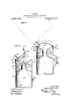
- FIG. 1 is a perspective view of a safety combination powder and fuse can or receptacle constructed in accordance with the present invention.
- Fig. 2 represents a'section taken vertically through the can or receptacle shown in Fig.
- Fig. 3 is a view similar to Fig. 2 showing a slightly modified construction of the can or receptacle.
- Figs 4 represents a transverse sectlon throu h the can 'or receptacle on the' line.
- the present invention is applicable par: ticularly to containers for powder or other explosives and fuses, it providing a combination powder and fuse .can orreceptacle which is especially adapted for use by,
- the can or receptacle is preferablymade of sheet metal, it comprising, as shown in Figs. 1 and 2, a cylindrical wall lhaving aclosed bottom .2 and a par-,
- tition 3 forming a chamberor compartment 4. to contain a supply of powder or other explosive.
- the partition 3 may be secured within the cylindrical wall 1 in any suitable way such, for example, as by fitting its periphery into a groove 5'formed by beading the wall 1. vided with a spout 6 which is preferably tapered slightly, as shown, and acap or other closure 7 is provided for this spout,
- Thispartition 8 is also pro-' the cap or closure shown in the present instance being adapted to fit into the mouth of the spout 6.
- the wall 1 of the can or? receptacle extends for a suitable distance abovethe partition 3 and it forms withjthe partition 3 and the spout 6 anannular chamber or compartment 8 which provides a space to contain'a supply. of fuse.
- the fuse is contained in the compart ment 8 in the form of a coil surrounding the spout 6.
- it is preferably formed with suitable corrugations 9, as shown.
- the top of the fusecompartment 8 is adapted-to be closedby a'cover whichperforms the function of protecting the fuse in the compartment 8 from ignition or from moisture, and this cover also provides a chamber through which the powder flows whenthe canis being filled with powder the wall 1 of the can.
- the cover is composed of sheet metal and comprises a top 10, which is advantageously made in the form of a truncated cone, and a hopperll, which is advantageously constructed in the form of an inverted truncated cone, or, in other words, the hopper 11 slopes downwardly in a direction from its periphery toward its center.
- the peripheries of the top 10 and the hopper 11 are united in any suitable way such, for example, as by the beads 12, andan annular flange 13 extends downwardly from the periphery of the cover so formed and is adapted to fit detachably over the upper end of Any suitable means may be provided for removably securing the cover upon the body of the can, bayonet joints 14 being provided for that purpose in the present instance.
- the top 10 and hopper 11 provide a chamber or compartment 15 between them and access may be had to such chamber through an opening provided by a lid 16.
- This lid may be mounted in different ways, it being shown hinged, at 17, to the top 10 and provided with a spring catch 18 which serves to normally retain the lid in closed position.
- the cap or closure 7 of the spout 6 may be provided with a handle 19 to facilitate its application and removal relatively to the spout 6, and suitable means such, for example, as a projection 20 may be provided to prevent the cap or closure 7 from entering too far into the spout 6.
- the hopper 11 is pro vided with a downwardly extending flange 21 which is adapted to fit upon the outside of the spout 6, it being preferably tapered slightly, as shown, to correspond with the taper of the spout 6.
- a pouring spout 22 is formed in the top 10, preferably adjacent to the periphery thereof.
- a stiffening rib 23 is formed across the top 10 adjacent to the hinge 17.
- Fig. 3 shows a can or receptacle constructed in accordance with the present invention when made up from a powder can similar to those as heretofore used.
- the powder can embodies a cylindrical side wall 1, a closed bottom 2 and a flaring top 3*, forming a powder chamber or compartment 4*, and the top 3 is formed with a filling spout 6
- the fuse compartment is formed by a cylindrical wall 1 which surrounds the spout 6 and has its lower'edge soldered or otherwise secured to the owder can aTong the upper edge thereof.
- he construction shown in Fig. 3 is otherwise the same as that shown in Figs. 1 and 2.
- a bail 24 may be provided to facilitate carrying of the can or receptacle, and inFigs. 1"and2, the can or receptacle is lid 16 is opened, the cap or closure 7 is re- 7 moved from the spout 6, the pouring spout 22 is inserted into the tap or opening in a keg containing powder, and the keg containing the powder is then tilted so as to cause the powder to run into the can through the spout 22, the chamber or compartment 15, and the spout 6, this being continued until the powder chamber 4 is filled. The powder keg is then removed from the spout 22 and the cap or closure 7 is introduced into the spout 6.
- the powder which enters the chamber or compartment 15 will all flow into the compartment 4, owing to the sloping sides of the hopper 11.
- this operation exposing the top of the fuse chamber 8, and the fuse may then be placed in this compartment, the fuse being preferably in the form of a coil encircling the spout 6.
- the lid 16 is opened and the cap or closure 7 is removed from the spout 6 as before, the lid 16 being thereafter closed, and the can is then tilted so that the powder runs from the spout 22.
- the can is returned to an upright position
- any powder remaining in the chamber or compartment 15 will return to the compartment 4, owing to the sloping form of the hopper 11, and the lid 16 may then be opened, the cap or closure 7 replaced in the spout 6, and the lid 16 may I then be closed.
- a combination powder and fuse can constructed in accordance with thepresent in vention possesses the advantage of insuring safety at all times for the powder and the fuse, and, also, the powder and fuse are always protected from moisture. when properly handled is so constructed that the powder in the compartment 4 cannot be reached by sparks or the like which would cause ignition of the powder, and the fuse is also inclosed in a mannerto protect it from ignition.
- a safety powder can comprising a powder compartment having a spout communicating therewith, a chamber with which said spout communicates, said chamber having a spout communicating therewith and also having a bottomsloping to- The can ward the spout of said compartment, and means for closing the spout of the powder compartment to interrupt communication between the latter and said chamber.
- a safety powder can comprising a powder compartment having a spout communieating therewith, a member having a chamber the bottom of which slopes toward said spout, said member having an opening therein, and a closure for said spout accessible through said opening for insertion and removal relatively to said spout.
- a safety powder can comprising a powder compartment having a spout communieating therewith, a member having a chamber adapted to communicate with said spout, said member having an opening therein at one side thereof and also having a spout communicating therewith at the side thereof opposite to said opening, and a closure for the spout of the powder compartment accessible through said opening for insertion and removal.
- a safety powder can comprising apowder compartment having a spout in the top thereof, a member forming a chamber above said spout and having a bottom wall sloping toward said spout and terminating in a plane flush with the upper end thereof, and a closure for said spout accessible for manipulation through said chamber.
- a safety combination powder and fuse comprising a powder compartment having a spout projecting upwardly from the top thereof, a fuse compartment surrounding said spout above the powder compartment, and a member capable of being fitted upon and removed from the to of the fuse compartment and the top of said spout as a closure for the fuse compartment and having a bottom sloping toward said spout and terminating in a plane flush with the upper end thereof.
- a safety combination powder and fuse comprising a powder compartment having a spout projecting upwardly from the top thereof, a fuse compartment surrounding said spout above the powder compartment, and a member capable of being fitted upon and removed from the top of the fuse compartment and the top of said spout as a closure for the fuse compartment, said member having a chamber therein, the bottom of said chamber sloping toward said spout and terminating in a plane flush with the upper end thereof.
- a safety combination powder and fuse comprising a powder compartment having a spout projecting upwardly from the top thereof, a fuse compartment surrounding said spout above the powder compartment, and a member capable of being upon and removed from the top of the fuse compartment and the top of said spout as a closure for the fuse compartment, said member having a chamber therein, the bottom of such chamber sloping toward the spout of the powder compartment and also having a spout communicating with the chamber therein.
Landscapes
- Closures For Containers (AREA)
Description
H. 0. BROOKS.
SAFETY COMBINATION POWDER AND FUSE CAN.
APPLICATION FILED JULY 1, I916.
- Patented Aug. 14,1917.
I v iii/67250" 70Zzes6 $3 I Jizgk dBnoo H. 0. BROOKS.
SAFETY COMBINATION POWDER AND FUSE CAN.
APPLICATION r1110 JULY 1, I916.
1 ,237, 1 64. Patented Au 14, 1917.
2 SHEETSSHEET 2.
4 can or receptacle.
U TED sa us PANT o TEE.
HUGH O. BROOKS, OF OTTUMWA, IOWA, ASSIG-NOR OF ONE-HALF TO JOHN L.
MCGLOTHLEN, OF OTTUMWA, IOWA.
SAFETY COMBINATION POWDER AND FUSE CAN.
7 Specification of Letters Patent. Patented Aug, 14;, 1917,
Application filed. July 1, 1916. Serial N 0. 107,105.
To all who 11bit may concern: 7
Be it known that I, HUGH O. BRooKs, a citizen of the United States, residing at Ottumwa, in the county of Wapello and State of Iowa, have invented new and useful Improvements in Safety C0mb1nat1on Powder and Fuse Cans, of which the following is a specification.
My present invention has for 1ts primary objects to provide a safety combinat on powder and fuse can or receptacle whlch 15 so constructed and operative that the explosive powder which is contained in one compartment is at all times protected from sparks or other sources of ignition; which is so constructed and operative that the handling of the can or receptacle in filling with powder and in pouring or wlthdrawing powder therefrom for blasting or other purposes is greatly facilitated; and whlch s provided with a fuse compartment wherein thefuse is'efiectively' protected from 1gI11 tion and from which compartment pieces of fuse may be readily taken when needed A further object of the invention is to provide a combination can or receptacle of this character which can be manufactured inexpensively and yet possess the advantages hereinbefore set forth. 7
To these and other ends, the invention consists in certain improvements, and co1nbinations and arrangements of parts, all as will be hereinafter more fully described the novel features being pointed out particularly in the claims at the end of the specification. 1'
In the accompanying draw ng Figure 1 is a perspective view of a safety combination powder and fuse can or receptacle constructed in accordance with the present invention.
Fig. 2 represents a'section taken vertically through the can or receptacle shown in Fig.
1, and it shows diagrammatically the mode of filling the can.
Fig. 3 is a view similar to Fig. 2 showing a slightly modified construction of the can or receptacle.
Figs 4 represents a transverse sectlon throu h the can 'or receptacle on the' line.
4-4 (If Fig. 2, and I Fig. 5 is a sectional perspect ve, partly broken away, of the upper portion of the Similar parts are designated by the same reference characters in the several views.
The present invention is applicable par: ticularly to containers for powder or other explosives and fuses, it providing a combination powder and fuse .can orreceptacle which is especially adapted for use by,
miners or others engaged in blasting and similar operations whereby the handling of the powder or explosive and the fuse is greatly facilitated and safety is insured. The preferred embodiments of the invention are shown in the accompanying draw-.
ing and will be hereinafter described in detail, but it is to be understood that the inventionis not restricted to the precise con-- struction shown, as equivalent constructions are contemplated and will be included,
within the scope of the claims. I
The can or receptacle, according to the present embodiments of the invention, is preferablymade of sheet metal, it comprising, as shown in Figs. 1 and 2, a cylindrical wall lhaving aclosed bottom .2 and a par-,
tition 3 forming a chamberor compartment 4. to contain a supply of powder or other explosive. The partition 3 may be secured within the cylindrical wall 1 in any suitable way such, for example, as by fitting its periphery into a groove 5'formed by beading the wall 1. vided with a spout 6 which is preferably tapered slightly, as shown, and acap or other closure 7 is provided for this spout,
The top of the fusecompartment 8 is adapted-to be closedby a'cover whichperforms the function of protecting the fuse in the compartment 8 from ignition or from moisture, and this cover also provides a chamber through which the powder flows whenthe canis being filled with powder the wall 1 of the can.
and also when powder is being poured from the can. Preferably, and as shown, the cover is composed of sheet metal and comprises a top 10, which is advantageously made in the form of a truncated cone, and a hopperll, which is advantageously constructed in the form of an inverted truncated cone, or, in other words, the hopper 11 slopes downwardly in a direction from its periphery toward its center. The peripheries of the top 10 and the hopper 11 are united in any suitable way such, for example, as by the beads 12, andan annular flange 13 extends downwardly from the periphery of the cover so formed and is adapted to fit detachably over the upper end of Any suitable means may be provided for removably securing the cover upon the body of the can, bayonet joints 14 being provided for that purpose in the present instance. The top 10 and hopper 11 provide a chamber or compartment 15 between them and access may be had to such chamber through an opening provided by a lid 16. This lid may be mounted in different ways, it being shown hinged, at 17, to the top 10 and provided with a spring catch 18 which serves to normally retain the lid in closed position. The cap or closure 7 of the spout 6 may be provided with a handle 19 to facilitate its application and removal relatively to the spout 6, and suitable means such, for example, as a projection 20 may be provided to prevent the cap or closure 7 from entering too far into the spout 6. The hopper 11 is pro vided with a downwardly extending flange 21 which is adapted to fit upon the outside of the spout 6, it being preferably tapered slightly, as shown, to correspond with the taper of the spout 6. A pouring spout 22 is formed in the top 10, preferably adjacent to the periphery thereof. Preferably, and as shown, a stiffening rib 23 is formed across the top 10 adjacent to the hinge 17.
The construction shown in Fig. 3 is similar to that shown in Figs. 1 and 2, but Fig. 3 shows a can or receptacle constructed in accordance with the present invention when made up from a powder can similar to those as heretofore used. In Fig. 8, the powder can embodies a cylindrical side wall 1, a closed bottom 2 and a flaring top 3*, forming a powder chamber or compartment 4*, and the top 3 is formed with a filling spout 6 The fuse compartment is formed by a cylindrical wall 1 which surrounds the spout 6 and has its lower'edge soldered or otherwise secured to the owder can aTong the upper edge thereof. he construction shown in Fig. 3 is otherwise the same as that shown in Figs. 1 and 2. In both instances, a bail 24 may be provided to facilitate carrying of the can or receptacle, and inFigs. 1"and2, the can or receptacle is lid 16 is opened, the cap or closure 7 is re- 7 moved from the spout 6, the pouring spout 22 is inserted into the tap or opening in a keg containing powder, and the keg containing the powder is then tilted so as to cause the powder to run into the can through the spout 22, the chamber or compartment 15, and the spout 6, this being continued until the powder chamber 4 is filled. The powder keg is then removed from the spout 22 and the cap or closure 7 is introduced into the spout 6. During this filling operation, the powder which enters the chamber or compartment 15 will all flow into the compartment 4, owing to the sloping sides of the hopper 11. In order to introduce the fuse into the fuse compartment 8, it is only necessary to detach the cover composed of the top 10 and hopper 11, this operation exposing the top of the fuse chamber 8, and the fuse may then be placed in this compartment, the fuse being preferably in the form of a coil encircling the spout 6. When it is desired to pour powder from the can, the lid 16 is opened and the cap or closure 7 is removed from the spout 6 as before, the lid 16 being thereafter closed, and the can is then tilted so that the powder runs from the spout 22. When the desired amount of powder has been poured from the can, the can is returned to an upright position,
whereupon any powder remaining in the chamber or compartment 15 will return to the compartment 4, owing to the sloping form of the hopper 11, and the lid 16 may then be opened, the cap or closure 7 replaced in the spout 6, and the lid 16 may I then be closed.
A combination powder and fuse can constructed in accordance with thepresent in vention possesses the advantage of insuring safety at all times for the powder and the fuse, and, also, the powder and fuse are always protected from moisture. when properly handled is so constructed that the powder in the compartment 4 cannot be reached by sparks or the like which would cause ignition of the powder, and the fuse is also inclosed in a mannerto protect it from ignition.
I claim as my invention A 1. A safety powder can comprising a powder compartment having a spout communicating therewith, a chamber with which said spout communicates, said chamber having a spout communicating therewith and also having a bottomsloping to- The can ward the spout of said compartment, and means for closing the spout of the powder compartment to interrupt communication between the latter and said chamber.
2. A safety powder can comprising a powder compartment having a spout communieating therewith, a member having a chamber the bottom of which slopes toward said spout, said member having an opening therein, and a closure for said spout accessible through said opening for insertion and removal relatively to said spout.
3. A safety powder can comprising a powder compartment having a spout communieating therewith, a member having a chamber adapted to communicate with said spout, said member having an opening therein at one side thereof and also having a spout communicating therewith at the side thereof opposite to said opening, and a closure for the spout of the powder compartment accessible through said opening for insertion and removal.
4. A safety powder can comprising apowder compartment having a spout in the top thereof, a member forming a chamber above said spout and having a bottom wall sloping toward said spout and terminating in a plane flush with the upper end thereof, and a closure for said spout accessible for manipulation through said chamber.
5. A safety combination powder and fuse can comprising a powder compartment having a spout projecting upwardly from the top thereof, a fuse compartment surrounding said spout above the powder compartment, and a member capable of being fitted upon and removed from the to of the fuse compartment and the top of said spout as a closure for the fuse compartment and having a bottom sloping toward said spout and terminating in a plane flush with the upper end thereof.
6. A safety combination powder and fuse can comprising a powder compartment having a spout projecting upwardly from the top thereof, a fuse compartment surrounding said spout above the powder compartment, and a member capable of being fitted upon and removed from the top of the fuse compartment and the top of said spout as a closure for the fuse compartment, said member having a chamber therein, the bottom of said chamber sloping toward said spout and terminating in a plane flush with the upper end thereof.
7. A safety combination powder and fuse can comprising a powder compartment having a spout projecting upwardly from the top thereof, a fuse compartment surrounding said spout above the powder compartment, and a member capable of being upon and removed from the top of the fuse compartment and the top of said spout as a closure for the fuse compartment, said member having a chamber therein, the bottom of such chamber sloping toward the spout of the powder compartment and also having a spout communicating with the chamber therein.
communicate with the spout of the powder,
compartment and also having a spout communicating with the chamber therein, and a lid through which access may be had to such chamber, and means for closing the spout of the powder compartment.
In testimony whereof I have hereunto set my hand in presence of two subscribing witnesses.
HUGH O. BROOKS.
Witnesses:
WM. GROOMS, G. E. PALMQUIST.
Copies of this patent may be obtained for five cents each, by addressing the Commissioner of Patents,
Washington, D. c.
tted
Priority Applications (1)
| Application Number | Priority Date | Filing Date | Title |
|---|---|---|---|
| US10710516A US1237164A (en) | 1916-07-01 | 1916-07-01 | Safety combination powder and fuse can. |
Applications Claiming Priority (1)
| Application Number | Priority Date | Filing Date | Title |
|---|---|---|---|
| US10710516A US1237164A (en) | 1916-07-01 | 1916-07-01 | Safety combination powder and fuse can. |
Publications (1)
| Publication Number | Publication Date |
|---|---|
| US1237164A true US1237164A (en) | 1917-08-14 |
Family
ID=3304983
Family Applications (1)
| Application Number | Title | Priority Date | Filing Date |
|---|---|---|---|
| US10710516A Expired - Lifetime US1237164A (en) | 1916-07-01 | 1916-07-01 | Safety combination powder and fuse can. |
Country Status (1)
| Country | Link |
|---|---|
| US (1) | US1237164A (en) |
Cited By (1)
| Publication number | Priority date | Publication date | Assignee | Title |
|---|---|---|---|---|
| US20040172782A1 (en) * | 2003-03-07 | 2004-09-09 | Smith James F. | Vacuum canister and mounting bracket for use therewith |
-
1916
- 1916-07-01 US US10710516A patent/US1237164A/en not_active Expired - Lifetime
Cited By (2)
| Publication number | Priority date | Publication date | Assignee | Title |
|---|---|---|---|---|
| US20040172782A1 (en) * | 2003-03-07 | 2004-09-09 | Smith James F. | Vacuum canister and mounting bracket for use therewith |
| US7080425B2 (en) * | 2003-03-07 | 2006-07-25 | H-P Products, Inc. | Vacuum canister and mounting bracket for use therewith |
Similar Documents
| Publication | Publication Date | Title |
|---|---|---|
| US917649A (en) | Safety cartridge-loader. | |
| US3687076A (en) | Field sensitized explosive package | |
| MX2008001994A (en) | Container closure assembly. | |
| US1237164A (en) | Safety combination powder and fuse can. | |
| US1471793A (en) | Carbide container | |
| US979072A (en) | Combined can container and perforator. | |
| US751157A (en) | Powder-can | |
| US470838A (en) | Ments | |
| US1952558A (en) | Nonrefillable liquid-dispensing can | |
| US1020413A (en) | Oil-can. | |
| US1808801A (en) | Volatile liquid container | |
| US1555591A (en) | Dispensing container | |
| US915560A (en) | Powder-container and measuring-can. | |
| US959012A (en) | Closing device for cans or the like. | |
| US640495A (en) | Non-explosive oil-can. | |
| US1941929A (en) | Nonrefillable container | |
| US442638A (en) | John a | |
| US800613A (en) | Powder-cartridge filler. | |
| US987583A (en) | Non-explosive oil-can. | |
| US981457A (en) | Cap for milk-bottles. | |
| US260364A (en) | Ash-barrel and coal-hod cover | |
| US986429A (en) | Safety-can for hydrocarbon liquids. | |
| US971055A (en) | Spout for powder-cans. | |
| US150820A (en) | Improvement in oil-cans | |
| US450465A (en) | Cartridge-filler |