US12355148B2 - Antenna apparatus having chassis portion - Google Patents
Antenna apparatus having chassis portion Download PDFInfo
- Publication number
- US12355148B2 US12355148B2 US16/892,239 US202016892239A US12355148B2 US 12355148 B2 US12355148 B2 US 12355148B2 US 202016892239 A US202016892239 A US 202016892239A US 12355148 B2 US12355148 B2 US 12355148B2
- Authority
- US
- United States
- Prior art keywords
- antenna
- radome
- chassis
- spacer
- housing
- Prior art date
- Legal status (The legal status is an assumption and is not a legal conclusion. Google has not performed a legal analysis and makes no representation as to the accuracy of the status listed.)
- Active
Links
Images


Classifications
-
- H—ELECTRICITY
- H01—ELECTRIC ELEMENTS
- H01Q—ANTENNAS, i.e. RADIO AERIALS
- H01Q1/00—Details of, or arrangements associated with, antennas
- H01Q1/42—Housings not intimately mechanically associated with radiating elements, e.g. radome
- H01Q1/428—Collapsible radomes; rotatable, tiltable radomes
-
- H—ELECTRICITY
- H01—ELECTRIC ELEMENTS
- H01Q—ANTENNAS, i.e. RADIO AERIALS
- H01Q1/00—Details of, or arrangements associated with, antennas
- H01Q1/02—Arrangements for de-icing; Arrangements for drying-out ; Arrangements for cooling; Arrangements for preventing corrosion
-
- H—ELECTRICITY
- H01—ELECTRIC ELEMENTS
- H01Q—ANTENNAS, i.e. RADIO AERIALS
- H01Q1/00—Details of, or arrangements associated with, antennas
- H01Q1/12—Supports; Mounting means
- H01Q1/1207—Supports; Mounting means for fastening a rigid aerial element
-
- H—ELECTRICITY
- H01—ELECTRIC ELEMENTS
- H01Q—ANTENNAS, i.e. RADIO AERIALS
- H01Q1/00—Details of, or arrangements associated with, antennas
- H01Q1/12—Supports; Mounting means
- H01Q1/1207—Supports; Mounting means for fastening a rigid aerial element
- H01Q1/1228—Supports; Mounting means for fastening a rigid aerial element on a boom
-
- H—ELECTRICITY
- H01—ELECTRIC ELEMENTS
- H01Q—ANTENNAS, i.e. RADIO AERIALS
- H01Q1/00—Details of, or arrangements associated with, antennas
- H01Q1/12—Supports; Mounting means
- H01Q1/125—Means for positioning
-
- H—ELECTRICITY
- H01—ELECTRIC ELEMENTS
- H01Q—ANTENNAS, i.e. RADIO AERIALS
- H01Q1/00—Details of, or arrangements associated with, antennas
- H01Q1/12—Supports; Mounting means
- H01Q1/22—Supports; Mounting means by structural association with other equipment or articles
- H01Q1/2283—Supports; Mounting means by structural association with other equipment or articles mounted in or on the surface of a semiconductor substrate as a chip-type antenna or integrated with other components into an IC package
-
- H—ELECTRICITY
- H01—ELECTRIC ELEMENTS
- H01Q—ANTENNAS, i.e. RADIO AERIALS
- H01Q1/00—Details of, or arrangements associated with, antennas
- H01Q1/36—Structural form of radiating elements, e.g. cone, spiral, umbrella; Particular materials used therewith
- H01Q1/38—Structural form of radiating elements, e.g. cone, spiral, umbrella; Particular materials used therewith formed by a conductive layer on an insulating support
-
- H—ELECTRICITY
- H01—ELECTRIC ELEMENTS
- H01Q—ANTENNAS, i.e. RADIO AERIALS
- H01Q1/00—Details of, or arrangements associated with, antennas
- H01Q1/42—Housings not intimately mechanically associated with radiating elements, e.g. radome
-
- H—ELECTRICITY
- H01—ELECTRIC ELEMENTS
- H01Q—ANTENNAS, i.e. RADIO AERIALS
- H01Q1/00—Details of, or arrangements associated with, antennas
- H01Q1/42—Housings not intimately mechanically associated with radiating elements, e.g. radome
- H01Q1/422—Housings not intimately mechanically associated with radiating elements, e.g. radome comprising two or more layers of dielectric material
-
- H—ELECTRICITY
- H01—ELECTRIC ELEMENTS
- H01Q—ANTENNAS, i.e. RADIO AERIALS
- H01Q15/00—Devices for reflection, refraction, diffraction or polarisation of waves radiated from an antenna, e.g. quasi-optical devices
- H01Q15/14—Reflecting surfaces; Equivalent structures
- H01Q15/141—Apparatus or processes specially adapted for manufacturing reflecting surfaces
- H01Q15/142—Apparatus or processes specially adapted for manufacturing reflecting surfaces using insulating material for supporting the reflecting surface
- H01Q15/144—Apparatus or processes specially adapted for manufacturing reflecting surfaces using insulating material for supporting the reflecting surface with a honeycomb, cellular or foamed sandwich structure
-
- H—ELECTRICITY
- H01—ELECTRIC ELEMENTS
- H01Q—ANTENNAS, i.e. RADIO AERIALS
- H01Q21/00—Antenna arrays or systems
-
- H—ELECTRICITY
- H01—ELECTRIC ELEMENTS
- H01Q—ANTENNAS, i.e. RADIO AERIALS
- H01Q21/00—Antenna arrays or systems
- H01Q21/06—Arrays of individually energised antenna units similarly polarised and spaced apart
- H01Q21/061—Two dimensional planar arrays
- H01Q21/065—Patch antenna array
-
- H—ELECTRICITY
- H01—ELECTRIC ELEMENTS
- H01Q—ANTENNAS, i.e. RADIO AERIALS
- H01Q21/00—Antenna arrays or systems
- H01Q21/06—Arrays of individually energised antenna units similarly polarised and spaced apart
- H01Q21/08—Arrays of individually energised antenna units similarly polarised and spaced apart the units being spaced along or adjacent to a rectilinear path
- H01Q21/10—Collinear arrangements of substantially straight elongated conductive units
-
- H—ELECTRICITY
- H01—ELECTRIC ELEMENTS
- H01Q—ANTENNAS, i.e. RADIO AERIALS
- H01Q23/00—Antennas with active circuits or circuit elements integrated within them or attached to them
-
- H—ELECTRICITY
- H01—ELECTRIC ELEMENTS
- H01Q—ANTENNAS, i.e. RADIO AERIALS
- H01Q3/00—Arrangements for changing or varying the orientation or the shape of the directional pattern of the waves radiated from an antenna or antenna system
- H01Q3/02—Arrangements for changing or varying the orientation or the shape of the directional pattern of the waves radiated from an antenna or antenna system using mechanical movement of antenna or antenna system as a whole
- H01Q3/04—Arrangements for changing or varying the orientation or the shape of the directional pattern of the waves radiated from an antenna or antenna system using mechanical movement of antenna or antenna system as a whole for varying one co-ordinate of the orientation
-
- H—ELECTRICITY
- H01—ELECTRIC ELEMENTS
- H01Q—ANTENNAS, i.e. RADIO AERIALS
- H01Q9/00—Electrically-short antennas having dimensions not more than twice the operating wavelength and consisting of conductive active radiating elements
- H01Q9/04—Resonant antennas
- H01Q9/0407—Substantially flat resonant element parallel to ground plane, e.g. patch antenna
- H01Q9/0414—Substantially flat resonant element parallel to ground plane, e.g. patch antenna in a stacked or folded configuration
-
- H—ELECTRICITY
- H01—ELECTRIC ELEMENTS
- H01Q—ANTENNAS, i.e. RADIO AERIALS
- H01Q1/00—Details of, or arrangements associated with, antennas
- H01Q1/12—Supports; Mounting means
- H01Q1/22—Supports; Mounting means by structural association with other equipment or articles
- H01Q1/2291—Supports; Mounting means by structural association with other equipment or articles used in Bluetooth® or Wi-Fi® devices of Wireless Local Area Networks [WLAN]
Definitions
- the present disclosure pertains to antenna apparatuses for satellite communication systems.
- Satellite communication systems generally involve Earth-based antennas in communication with a constellation of satellites in orbit.
- Earth-based antennas are, of consequence, exposed to weather and other environmental conditions. Therefore, described herein are antenna apparatuses and their housing assemblies designed with sufficient durability to protect internal antenna components while enabling radio frequency communications with a satellite communication system, such as a constellation of satellites.
- a housing for an antenna system having a plurality of antenna elements defining an antenna aperture includes: a chassis portion having an internal support portion for internal components for the plurality of antenna elements including a bonding portion for bonding an antenna stack assembly to the chassis portion; and a radome portion configured for coupling to the chassis portion to define an inner chassis chamber.
- a housing for an antenna system having a plurality of antenna elements defining an antenna aperture includes: a chassis portion having an internal support portion for internal components for the plurality of antenna elements including a bonding portion for bonding an antenna stack assembly to the chassis portion; and a radome portion configured for coupling to the chassis portion to define an inner chassis chamber.
- the bonding portion may include a plurality of bonding bars.
- the bonding portion may include adhesive between the plurality of bonding bars and the antenna stack assembly.
- the plurality of bonding bars may be oriented with adjacent bonding bars in a parallel configuration.
- the housing may further include a heat sink extending from an external surface of the chassis portion.
- the heat sink may include a plurality of fins.
- the plurality of fins may be arranged in a parallel configuration.
- the plurality of fins may be oriented in an orientation perpendicular to the orientation of the bonding portion including a plurality of bonding bars.
- the housing may further include thermal interface material coupled between the chassis portion and the antenna stack assembly.
- the chassis portion may be an in-plane heat spreader.
- the chassis portion may be made from a thermally conductive material.
- the chassis portion may be made from metal.
- FIG. 2 B is an isometric bottom view depicting exemplary antenna apparatus of FIG. 2 A , showing a housing secured to a leg, wherein the leg is shown mounted to a surface according to one embodiment of the present disclosure;
- FIG. 3 A is an isometric exploded view depicting an exemplary antenna apparatus including the housing and the antenna stack assembly according to one embodiment of the present disclosure
- FIGS. 3 B and 3 C are cross-sectional views of the housing assembly of the antenna assembly of FIGS. 2 A and 2 B ;
- FIG. 4 is a cross-sectional view of the antenna stack assembly of the antenna apparatus of FIG. 3 ;
- FIG. 5 A is a top view of an upper patch antenna layer of the antenna stack assembly of the antenna apparatus of FIG. 3 ;
- FIG. 5 E is a top view of the lower patch antenna layer of the antenna stack assembly of the antenna apparatus of FIG. 3 ;
- FIGS. 6 A and 6 B are isometric views of a single antenna element in an antenna element array in the antenna stack assembly of the antenna apparatus of FIG. 3 ;
- FIG. 7 A is a partial cross-sectional view of the antenna apparatus of FIG. 3 showing the antenna stack assembly inside the housing;
- FIG. 7 B is a close-up partial cross-sectional view of the antenna apparatus of FIG. 3 showing the fastening system
- FIG. 7 C is an isometric partial cut-away view of the antenna apparatus of FIG. 3 ;
- FIGS. 8 A, 8 B, and 8 C are top views of adhesive patterns on the various layers of the antenna stack assembly in accordance with embodiments of the present disclosure
- FIGS. 9 A and 9 B are isometric exploded views depicting an exemplary antenna apparatus including a dielectric spacer according to another embodiment of the present disclosure
- FIG. 10 is a top view of a chassis of the antenna apparatus of FIG. 3 ;
- FIGS. 11 A and 11 B are isometric partial cut-away view showing a disengaged and engaged fastener system for the antenna assembly of FIGS. 2 A and 2 B in accordance with embodiments of the present disclosure
- FIG. 12 is an exploded view of the housing assembly components of the antenna assembly of FIGS. 2 A and 2 B in accordance with embodiments of the present disclosure
- FIG. 13 is a close-up partial cross-sectional view of the antenna assembly of FIGS. 2 A and 2 B showing heat transfer pathways in accordance with embodiments of the present disclosure
- FIGS. 14 and 15 are data schematics showing heat transfer effects of the antenna assembly of FIGS. 2 A and 2 B in operation in accordance with embodiments of the present disclosure
- FIGS. 16 and 17 are isometric views of an antenna apparatus with a housing portion in different configurations relative to a mounting system in accordance with embodiments of the present disclosure
- FIGS. 18 and 19 are exploded views of the antenna apparatus of FIGS. 16 and 17 from respective top and bottom perspectives;
- FIG. 20 is a side exploded view of the antenna apparatus of FIGS. 16 and 17 ;
- FIGS. 21 and 22 are respective exploded and partial cross-sectional views of a radome portion of the antenna apparatus of FIGS. 16 and 17 ;
- FIGS. 23 and 24 are respective isometric and top views of a chassis portion of the antenna apparatus of FIGS. 16 and 17 ;
- FIG. 25 is an up-close isometric view of a portion of the chassis portion of the antenna apparatus of FIGS. 16 and 17 ;
- FIGS. 26 and 27 are respective isometric and bottom views of chassis portion of the antenna apparatus of FIGS. 16 and 17 showing a heat sink;
- FIGS. 28 , 29 , and 30 are exploded views of the mounting system of the antenna apparatus of FIGS. 16 and 17 ;
- FIGS. 33 A, 33 B, and 33 C are side views of the antenna apparatus of FIGS. 16 and 17 showing the antenna apparatus in various different tilt positions.
- references in the specification to “one embodiment,” “an embodiment,” “an illustrative embodiment,” etc., indicate that the embodiment described may include a particular feature, structure, or characteristic, but every embodiment may or may not necessarily include that particular feature, structure, or characteristic. Moreover, such phrases are not necessarily referring to the same embodiment. Further, when a particular feature, structure, or characteristic is described in connection with an embodiment, it is submitted that it is within the knowledge of one skilled in the art to affect such feature, structure, or characteristic in connection with other embodiments whether or not explicitly described.
- Embodiments of the present disclosure are directed to antenna apparatuses including antenna systems designed for sending and/or receiving radio frequency signals to and/or from a satellite or a constellation of satellites.
- the antenna systems of the present disclosure may be employed in communication systems providing high-bandwidth, low-latency network communication via a constellation of satellites.
- Such constellation of satellites may be in a non-geosynchronous Earth orbit (GEO), such as a low Earth orbit (LEO).
- GEO non-geosynchronous Earth orbit
- LEO low Earth orbit
- FIG. 1 illustrates a not-to-scale embodiment of an antenna and satellite communication system 100 in which embodiments of the present disclosure may be implemented.
- an Earth-based endpoint or user terminal 102 is installed at a location directly or indirectly on the Earth's surface such as house or other a building, tower, a vehicle, or another location where it is desired to obtain communication access via a network of satellites.
- An Earth-based endpoint terminal 102 may be in Earth's troposphere, such as within about 10 kilometers (about 6.2 miles) of the Earth's surface, and/or within the Earth's stratosphere, such as within about 50 kilometers (about 31 miles) of the Earth's surface, for example on a geographical stationary or substantially stationary object, such as a platform or a balloon.
- a communication path may be established between the endpoint terminal 102 and a satellite 104 .
- the first satellite 104 in turn, establishes a communication path with a gateway terminal 106 .
- the satellite 104 may establish a communication path with another satellite prior to communication with a gateway terminal 106 .
- the gateway terminal 106 may be physically connected via fiber optic, Ethernet, or another physical connection to a ground network 108 .
- the ground network 108 may be any type of network, including the Internet. While one satellite 104 is illustrated, communication may be with and between a constellation of satellites.
- the endpoint or user terminal 102 may include an antenna apparatus 200 , for example, as illustrated in FIGS. 2 A and 2 B .
- the antenna apparatus may include a housing assembly 202 , which includes a radome portion 206 and a lower enclosure 204 that couples to the radome portion 206 .
- the housing assembly 202 may also include a chassis portion 345 (see FIG. 3 ) in addition to or in lieu of a lower enclosure.
- An antenna system and other electronic components, as described below, are disposed within the housing assembly 202 .
- the antenna apparatus 200 and its housing 202 may include materials for durability and reliability in an outdoor environment as well as facilitating the sending and/or receiving radio frequency signals to and/or from a satellite or a constellation of satellites with the satellites 104 .
- FIG. 2 B illustrates a perspective view of an underside of the antenna apparatus 200 .
- the antenna apparatus 200 may include a lower enclosure 204 that couples to the radome portion 206 to define the housing 202 .
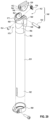
- the mounting system 210 includes a leg 216 and a base 218 .
- the base 218 may be securable to a surface S and configured to receive a bottom portion of the leg 216 .
- the leg 216 shown as a single mounting leg, may be defined by a generally hollow cylindrical or tubular body, although other shapes may be suitably employed. With a hollow configuration, any necessary wiring or electrical connections 220 may extend into and within the interior of the leg 204 up into the housing 202 of the antenna apparatus 200 .
- a tilting mechanism 240 (details not shown) disposed within the lower enclosure 204 permits a degree of tilting to point the face of the radome portion 206 at a variety of angles for optimized communication and for rain and snow run-off (see FIGS. 33 A, 33 B, 33 C ). Such tilting may be automatic or manual.
- FIGS. 16 - 33 C an alternate embodiment of an antenna apparatus is provided in FIGS. 16 - 33 C , including differences regarding the radome portion, the chassis, the leg, and the base.
- the antenna apparatus 200 is configured to be mounted on a mounting surface S for an unimpeded view of the sky.
- the antenna apparatus 200 may be mounted at an Earth-based fixed position, for example, the roof or wall of a building, a tower, a natural structure, a ground surface, an atmospheric platform or balloon, or on a moving vehicle, such as a land vehicle, airplane, or boat, or to any other appropriate mounting surface having an unimpeded view of with the sky for satellite communication.
- the antenna apparatus 200 includes an antenna system designed for sending and/or receiving radio frequency signals to and/or from a satellite or a constellation of satellites.
- the antenna system as described below, is disposed in the housing assembly 202 and may include an antenna aperture 208 (see FIGS. 2 A and 5 A ) defining an area for transmitting and receiving signals, such as a phased array antenna system or another antenna system.
- the antenna apparatus 200 may include other electronic components within the housing assembly 202 , for example, which may include, but are not limited to beamformers, a modem, a Wifi card and/or Wifi antennas, a GPS antenna, as well as other components.
- the antenna stack assembly 300 includes a plurality of antenna components, which may include a printed circuit board (PCB) assembly 380 configured to couple to other electrical components that are disposed within the housing assembly 202 .
- the antenna stack assembly 300 includes a phased array antenna assembly made up from a plurality of individual antenna elements (see FIGS. 6 A and 6 B ) configured in an array (see FIGS. 5 A and 5 B ).
- the components of the phased array antenna assembly may be mechanically and electrically supported by a printed circuit board (PCB) assembly 380 .
- PCB printed circuit board
- the radome portion 206 is a structural surface or enclosure that protects the antenna stack assembly 300 , providing an environmental barrier and impact resistance. As described in detail below, the radome portion 206 may incorporate features for snow, rain, and other dirt and moisture mitigation.
- radome portions in accordance with embodiments of the present disclosure are designed to mitigate the accumulation of snow, rain, and other moisture.
- radome portions described herein may be constructed from material that minimally attenuates the radio frequency signals transmitted or received by the antenna system of the antenna apparatus 200 .
- the radome portion 206 has a planar top surface 220 extending from a first end 222 to a second end 224 .
- the radome portion 206 has a circular planar top surface 220 .
- the radome portion 206 may have another shape for the planar portion of the top surface, such as square, ovoid, rectangular, polygonal, or another other suitable shape.
- the first end 222 is on the first outer edge 226 of the radome portion 206 and the second end 224 is on the second outer edge 228 of the radome portion 206 .
- the planar top surface 220 need not extend from the first outer edge 226 to the second outer edge 228 of the radome portion 206 . Instead, the planar top surface 220 may only extend for a portion of the distance from the first outer edge to the second outer edge of the radome portion 206 .
- the planar top surface 220 of the radome portion 206 may have a raised planar top surface between outer edges. While illustrated as having a top planar surface, in other embodiments, a suitable radome may have curvature across its surface rather than being planar.
- the radome portion 206 is designed and configured to have a uniform thickness from the first end 222 to the second end 224 of the planar top surface 220 .
- individual antenna elements 304 that make up the antenna array 308 defining the antenna aperture 208 of the illustrated embodiment are configured to be equally distanced from the planar top surface 220 of the radome portion 206 .
- a bottom planar surface of the radome portion 206 (see FIG. 4 ) is designed to be adjacent and/or equally distanced from a top surface of a patch antenna assembly 334 , as described in greater detail below.
- a planar top surface 220 for the radome portion 206 allows for minimal tuning of specific antenna elements 212 in an antenna array to account for differences in radome thickness and/or differences in spacing between the radome portion 206 and each of the individual antenna elements 304 in the antenna array 308 .
- all of the individual antenna elements 304 in the antenna array 308 can be tuned the same to account for attenuation of the electromagnetic signal by the radome portion 206 and also for impedance matching between the antenna elements 304 and the radome portion 206 .
- the radome portion 206 of the illustrated embodiment includes a plurality of layers 305 and 310 .
- the plurality of layers includes a radome layer (or radome) 305 and a radome spacer layer (or radome spacer) 310 for providing mechanical and environmental protection to the antenna aperture 208 and other electrical components associated with the housing assembly 202 of the antenna apparatus 200 .
- the radome 305 and radome spacer 310 may together be referred to as the radome portion or radome assembly 206 .
- the radome 305 is designed to be an outer layer, which is exposed to the outdoor environment and has mechanical properties of good strength to weight ratios, a high modulus of elasticity for stiffness and resistance to deformation, and a low coefficient of thermal expansion (CTE). So as not to impede RF signals, the radome 305 has electrical properties of a low dielectric constant, a low loss tangent, and a low coefficient of thermal expansion (CTE). In addition, in some embodiments, the radome 305 has chemical properties of bondability for bonding with adhesive and low or near zero water absorption. Without such bondability, the radome lay-up can buckle in extreme weather conditions.
- the radome 305 is designed to maintain high mechanical values and electrical insulating qualities in both dry and humid conditions over thermal cycles between ⁇ 40° C. and 85° C.
- the radome 305 has high yield strength and a high enough modulus to spread load on the radome 305 to the radome spacer 310 .
- the radome 305 has a dielectric constant of less than 4.
- the radome 305 has a loss tangent of less than 0.001.
- the radome 305 may be constructed of a fiberglass base for mechanical strength.
- the fiberglass may be laminated with a polymer or copolymer of polyethylene, which may be functionalized with fluorine and/or chlorine.
- the laminate may be a fluorinated polymer (fluoro polymer), such as polytetrafluoroethylene (PTFE) or a copolymer of ethylene and chlorotrifluoethylene, such as ethylene chlorotrifluoroethylene (ECTFE).
- PTFE polytetrafluoroethylene
- ECTFE ethylene chlorotrifluoroethylene
- the radome 232 may be fiberglass-reinforced epoxy laminate material, such as FR-4 or NEMA grade FR-4.
- the radome 305 may be a lay-up made from a first layer made from fibrous material, such as fiberglass or Kevlar fibers, preimpregnated with a resin, such as an epoxy or polyethylene terephthalate (PET) resin.
- the radome 305 may include one or more additional layers that include UV protection and/or water mitigation.
- a second layer may be made from a fluorinated polymer (fluoropolymer), such as polytetrafluoroethylene (PTFE) to aid in hydrophobic properties resulting in beading of water droplets on the surface of the radome 305 .
- the second layer may include titanium dioxide doping at up to 10% for UV protection.
- LLDPE may be employed, and may have a melt index of from about 10 to about 30 g/min, or alternatively from about 15 to about 25 g/min, or alternatively about 20 g/min at 190° C./2.16 kg.
- a commercially available suitable LLDPE includes the Bapolene family of LLDPEs.
- Radome spacers 310 made from plastic may be formed by injection molding or any other suitable method of manufacture.
- radome spacers 310 may include UV additives to protect the radome spacer 310 from any UV light that passes through the radome 305 .
- the radome spacer 310 may be a plurality of spacer elements defining the space between the radome portion 305 and the top layer of the patch antenna assembly 334 .
- each of the plurality of apertures 315 may include a vertical pathway to align with each upper patch element 330 a of each individual antenna elements 304 in the antenna array 308 .
- the radome spacer 310 may be designed such that there is a low volume of solid material, with air making up a significant portion of the volume of the structure. The presence of air (which may also be considered the omission of solid material) in the radome spacer 310 reduces interference with the signal communication of the antenna elements 304 .
- the presence of solid material making up the cell walls of the radome spacer 310 provides structure to the antenna stack assembly 300 and allows for dissipation and flow of heat from the electrical components of the antenna stack assembly 300 through its conductive cell walls 316 .
- the radome spacer 310 includes an interior portion 327 defining a plurality of honeycomb cell walls 316 defining a plurality of honeycomb apertures 315 , and an exterior portion 328 extending around the outer perimeter of the interior portion 327 . Therefore, the interior portion 327 defining honeycomb cell walls may make up only a portion of the radome spacer 310 .
- the interior portion 327 may be present in greater than 75%, greater than 85%, or greater than 90%, greater than 95%, and in some embodiments 100% of the surface area of the radome spacer 310 .
- the exterior portion 328 of the radome spacer 310 may be of different construction than the interior portion 327 , for example, a solid or non-honeycomb construction, to provide integrity to the radome spacer 310 and the radome assembly 206 along its outer perimeter 339 .
- the cell walls 316 of the interior portion 327 radome spacer 310 may provide a greater proportion of air to mitigate any RF interference with antenna signals from the antenna array 308 .
- the volumetric ratio of air to solid surface area or the body of the radome spacer 310 is greater than about 50:50, or alternatively greater than about 65:45, or alternatively greater than about 75:25, or alternatively greater than about 80:20, or alternatively greater than about 85:15, or alternatively greater than about 90:10.
- the radome 305 and the radome spacer 310 may be joined to each other using suitable joining methods, as described in detail below.
- the radome portion 206 may be joined with a lower enclosure 204 to form the housing 202 of the antenna apparatus 200 , as described in greater detail below.
- the radome spacer 310 may include a plurality of projecting fasteners (see FIGS. 11 A and 11 B ) radially arranged around its perimeter for coupling with the lower enclosure 204 to define an inner chamber of the housing 202 (as described in greater detail below).
- the radome portion 206 may be joined to a chassis in lieu of a lower enclosure, as described in greater detail below (see FIG. 18 ).
- RF signal attenuation due to gain degradation can be significant as a result of rain or moisture accumulation on the planar top surface 220 of the radome portion 206 .
- water has a significant relative permittivity which can introduce a non-trivial interface for an antenna aperture causing RF reflection. Such RF reflection results in gain degradation in the RF signal.
- the planar top surface 220 of the radome 232 may include a top hydrophobic layer (not shown) having low surface energy to cause water to bead up and not spread out.
- a top hydrophobic layer may include a layer having hydrophobic paint or a polytetrafluoroethylene (PTFE) coating.
- the radome 232 may include additives, such as platicizers, within the radome 232 to cause the radome 232 have hydrophobic properties.
- the radome reduces gain degradation due to water accumulation. With no radome and water accumulation on the antenna aperture, gain degradation was found to be up to 3 dB. With a radome composed of about 3.0 mm foam in accordance with embodiments of the present disclosure, gain degradation was reduced to about 1 dB.
- the chassis portion 345 supports the electronic features of the antenna apparatus 200 , including any of the radome portion 206 , the antenna array 308 , the PCB assembly 380 , and any other electrical components contained in the housing assembly 202 , such as beamformers, the modem, GPS, Wi-Fi card, Wi-Fi antennas, etc.
- the chassis portion 345 may be a heat spreader designed and configured to conductively spread heat generated by the various electrical components to the outside environment.
- FIG. 5 A shows a schematic layout or lattice 308 of individual antenna elements 304 of a two-dimensional phased array antenna.
- the illustrated phased array antenna layout 308 includes antenna elements 304 that are arranged in a 2D array of M columns by N rows.
- the phased array antenna layout 308 has a generally circular or polygonal arrangement of the antenna elements 304 .
- the phased array antenna may have another arrangement of antenna elements, for example, a square arrangement, rectangular arrangement, or other polygonal arrangement of the antenna elements.
- the antenna elements 304 are arranged in multiple rows and columns and can be phase offset such that the phased array antenna emits a waveform in a preferred direction. When the phase offsets to individual antenna elements are properly applied, the combined wave front has a desired directivity of the main lobe.
- the antenna stack assembly 300 is designed to meet various goals of antenna performance, heat transfer, and manufacturability.
- antenna performance is most optimal if the upper and lower antenna patches 330 a and 370 a are spaced from each other by spacers that approximate air with a space above the upper patch 330 a that approximates air, while also being thermally conductive.
- Through-plane heat transfer vertically through the radome spacer 310 and the antenna spacer 335 requires the presence of thermally conductive material (for example, defining the cell walls) in the near vicinity of the upper and lower antenna patches 330 a and 370 a .
- the manufacturability of the radome spacer 310 and antenna spacer 335 is improved by a minimum wall thickness in the cell structure.
- a suitable plastic for the antenna spacer 335 may be thermally conductive and capable of dissipating heat through its structure, while also have a low dielectric constant.
- the antenna spacer 335 may be made from the same or similar materials as the radome spacer 310 and may have a dielectric constant of less than 3.0, and a thermal conductivity value of greater than 0.35 W/m-K or greater than 0.45 W/m-K.
- the radome spacer 310 may have similar dimensions, properties, and adhesive properties. However, the radome spacer 310 may have a different height than the antenna spacer 335 , for example, in the range of 2 mm to 3 mm.
- FIGS. 3 and 4 illustrate an exemplary antenna stack assembly 300 in the form of a plurality or stack of layers.
- the illustrated plurality of layers includes alternating layers of spacers bonded to other layers including antenna layers or layers including antenna elements or components, which may be for instance electronic layers, such as printed circuit board (PCB) layers.
- Adjacent layers may be bonded together using an adhesive (not shown in FIG. 3 , but shown in FIG. 4 ).
- the adhesive may be applied using a stenciling process and a pressing process as further described in FIGS. 8 A- 8 C below.
- the patterns employed facilitate bonding as well as providing bonding for the plurality of layers and support for the antenna stack assembly 300 without attenuating signal.
- the layers in the antenna stack assembly 300 layup include a radome assembly 206 , a patch antenna assembly 334 , a dielectric layer 375 , and a printed circuit board (PCB) assembly 380 .
- PCB printed circuit board
- an outer top layer of the antenna stack assembly 300 includes a radome portion 206 .
- the radome portion 206 is a radome assembly including a radome 305 and a radome spacer 310 .
- the spacing components are made from injection molded plastics having purposeful air gaps, which would be damaged under typical PCB lamination process.
- the adhesive may be curable over time, using UV curing techniques, and/or additives may be added for crosslinking the adhesive.
- the adhesive may have a dielectric constant of less than 3.0 and a thermal conductivity in the range of 0.1 to 0.5 W/m-K.
- a suitable adhesive may be an epoxy adhesive.
- Epoxy may be any adhesive composition formed from epoxy resins, epoxides, or compounds including epoxide functional groups.
- the epoxy adhesive may be a one-part self-curing epoxy or a two-part epoxy, either of which may include cross linkers or reactants such as amines, acids, acid derivatives such as anhydrides, thiols, or other functional groups which assist in hardening and cross-linking.
- the adhesive layer stack 390 which is a stack of adhesively coupled layers in the electronic assembly 300 includes the following structural layers: radome 305 , radome spacer 310 , upper patch antenna layer 330 , antenna spacer 335 , lower patch antenna layer 370 , and dielectric spacer 375 .
- the layers may be pressed by a heat press to aid in curing the adhesive to form a bonded adhesive layer stack 390 .
- the PCB assembly may also be adhered by adhesive bonding and heat pressed with the adhesive layer stack 390 as shown by arrow 398 in FIG. 4 .
- the lower antenna stack 340 may be adhered by heat press separately or together with the other layers in the adhesive layer stack 390 .
- the stack 390 and PCB assembly 380 may be disposed on chassis 345 as illustrated by arrows 395 , and enclosed in chamber 355 of the housing assembly 202 of the antenna apparatus 200 as illustrated by arrows 397 .
- the coupling of the housing assembly 202 may be achieved by mechanical coupling between radome portion 206 and the lower enclosure 208 (see arrows 397 ), as described in greater detail below.
- FIG. 4 illustrates a side sectional view of the layers of the adhesive layer stack 390 along with the PCB assembly 380 shown in FIG. 3 .
- the adhesive layer stack 390 includes an adhesive layer (numbered in the 400 series) between each of the structural layers making up adhesive layer stack 390 (radome 305 , radome spacer 310 , upper patch antenna layer 330 , antenna spacer 335 , lower patch antenna layer 370 , and dielectric spacer 375 ).
- adhesive layer 402 couples the radome 305 with the radome spacer 310 ; adhesive layer 404 couples the radome spacer 310 with the upper patch antenna layer 330 ; adhesive layer 406 couples the upper patch antenna layer with the antenna spacer 335 ; adhesive layer 408 couples the antenna spacer 335 with the lower patch antenna layer 370 ; and adhesive layer 410 couples the lower patch antenna layer 370 to the dielectric spacer 375 .
- an adhesive layer 412 couples the bottom portion of the adhesive layer stack 390 (e.g., the dielectric spacer 375 ) with the PCB assembly 380 .
- Arrow 398 indicates the coupling between the PCB assembly 380 and adhesive layer stack 390 .
- the adhesive layer stack 390 may be coupled together first, and then separately coupled with the PCB assembly 380 , or the adhesive layer stack 390 and PCB assembly 380 may be coupled simultaneously. In each instance, a heat press may be used, as further described below.
- the radome portion 206 (including the radome 305 and radome spacer 310 ) has been described above.
- FIG. 5 A illustrates a top view of the upper patch layer 330 and FIG. 5 B illustrated a portion of the upper patch layer 330 overlaid with the radome spacer 310 .
- the upper surface of the upper patch antenna layer 330 includes an interior portion 327 having a plurality of individual upper antenna patch elements 330 a that make up the upper patches of individual antenna elements 304 defining the antenna array 308 .
- the upper antenna patch elements 330 a may be a plurality of discrete individual dots, circles, modified circles, or other polygonal shapes made up of a conductive metal such as copper.
- the upper antenna patch elements 330 a may be separated from each other on the upper patch layer 330 by non-conductive portions of the upper patch antenna layer 330 between the upper antenna patch elements 330 a.
- gap section Between the exterior portion 328 and the interior portion 327 of the upper patch layer 330 is a gap section which may contain no conductive features.
- the gap section and the thieving section isolate the thermally constructive rim from the antenna elements.
- a GPS antenna portion 306 may be provided on the upper patch antenna layer 330 to facilitate GPS use in the electronic assembly 300 .
- the heat can also be dissipated by the heat dissipation features of the exterior portion 328 of the upper patch antenna layer 330 .
- the upper patch antenna layer 330 is a PCB substrate having a plurality of upper antenna patch elements 330 a .
- the features of the upper patch antenna layer 330 may be formed by suitable semiconductor processing to obtain the desired feature patterns and shapes.
- the housing assembly 202 is formed with the radome portion 206 (radome 305 and radome spacer 310 ) at the top and the lower enclosure 204 at the bottom to support with the components of the antenna apparatus therein. Further, all of the components, including the radome 305 , radome spacer 310 , the chassis 345 , and the lower enclosure 204 may all share a common central axis 562 represented by the dashed line 352 in FIG. 3 .
- the lower antenna stack 340 (made up of the antenna spacer 335 , the lower patch antenna layer 370 , dielectric layer 375 , and PCB assembly 375 ) has a different profile than the radome 305 , radome spacer 310 , and upper patch antenna layer 330 , such that these layers substantially align with each other when stacked.
- FIG. 7 A such alignment is illustrated in a cross-sectional side view of a portion of the housing assembly 202 .
- the radome 305 is coupled to the radome spacer 310 .
- the radome 305 resting inside a recessed area 323 on the radome spacer 310 defined by a lip 324 near the outer edge of the radome spacer 310 .
- the antenna stack assembly 300 including the upper patch antenna layer 330 and the lower antenna stack 340 may generate heat in operation. Further, other electrical components (not shown) associated with the antenna system within the inner chamber 355 may generate heat, such as a modem, Wi-Fi card and Wi-Fi antennas, GPS antenna, or other circuitry or PCB's. The heat generated by the antenna components or other electrical components may cause many of the components making up the housing assembly 202 and the antenna stack assembly 300 to expand and contract (grow and shrink). Further, weather conditions external the housing assembly 202 may involve changes in temperature, which also may impact the expansion and contraction of components making up housing assembly 202 .
- the lower enclosure 204 may be made up of a material, which may be different than the material of the radome spacer.
- the lower enclosure 204 may be made from metal or from a plastic have good stiffness and that does not creep at temperature.
- a drawback of a metal lower enclosure 204 is that it is more difficult to form the shape of such a metal component.
- a suitable plastic material for the lower enclosure may be a thermoplastic material, such as a polycarbonate or a polycarbonate and acrylic-styrene-acrylate terpolymer (ASA) blend that offers good resistance to both UV and moisture.
- ASA acrylic-styrene-acrylate terpolymer
- Other suitable materials may include thermoplastics, such as polypropylene (PP) or polyphenylene ether (PPE).
- the various components making up the housing assembly 202 may have different CTEs. As a result, the various components expand and contract by different degrees and therefore move relative to one another. Consequently, the different degrees of expansion and contraction can cause instability or threaten the structural integrity of the housing. Accordingly, the fasteners as disclosed herein permit the relative movement and sliding of the components relative to one another to accommodate the changes in size as expansion and contraction occurs.
- the coefficient of thermal expansion (CTE) of the lower enclosure 204 may be different than the CTE of the radome spacer 310 . Accordingly, the lower enclosure 204 may expand and contract a different degree and/or rate than the radome spacer 310 . Furthermore, the components bonded to the radome spacer 310 (such as the radome 305 , the upper patch antenna layer 330 , and the lower antenna stack 340 ) may also have different CTEs, and therefore, may expand and contract differently than the lower enclosure 204 .
- the radome spacer 310 and the antenna spacer 335 may be made from a conductive plastic material having a very high CTE, for example, more than 100 ppm/° C. In one non-limiting example, for LLDPE, the CTE of the radome spacer 310 is 150 ppm/° C. However, because the radome spacer 310 is disposed within and adhesively coupled to the adhesive layer stack 390 , the combined CTE changes to a much lower value.
- radome 305 , upper patch antenna layer 330 , lower patch antenna layer 370 , dielectric spacer 375 , and PCB assembly 380 may be PCBs or other non-plastic materials made from fiberglass, copper and other substrate materials, and may have a CTE of less than about 45 ppm/° C., alternatively equal to or less than about 30 ppm/° C., alternatively equal to or less than about 20 ppm/° C.
- the PCB components in the adhesive stack assembly 390 may have a CTE of about 14 ppm/° C.
- the combined CTE of the radome spacer 310 and the adhesive stack assembly 390 also becomes much lower, such as equal to or less than about 45 ppm/° C., alternatively equal to or less than about 30 ppm/° C., alternatively equal to or less than about 20 ppm/° C.
- the combined CTE of the radome spacer 310 and the adhesive stack assembly 390 is 17 ppm/° C.
- the plastic components are typically manufactured in temperature controlled environments. With temperature-controlled manufacturing, parts are manufactured to be within tolerances during assembly (which also may be in a temperature-controlled environment).
- the differences in CTE of the radome spacer 310 and the lower enclosure 350 , as well as in the other components of the antenna stack assembly 300 may cause the radome spacer 310 and the lower enclosure 350 to shift relative to one another as the components expand and contract. Accordingly, the plurality of projecting fasteners 520 and the plurality of receiving fasteners 560 are design to accommodate such shifting.
- the detents 346 around its perimeter of the chassis 345 , and the ports 332 in the upper patch antenna layer 330 through which the engaged projecting fasteners 520 and receiving fasteners 560 may pass are also designed and configured to allow a mismatch in expansion and contraction of the radome space 310 and the lower enclosure 204 .
- each one of the plurality of receiving fastener portions 360 are slidingly engaged with one of the plurality of projecting fastener portions 320 .
- a plurality of portals 322 are provided in the radome spacer 310 near the projecting fastener portion 320 for plastic manufacturing and for flexibility in the material as the projecting fastener portions 320 of the radome spacer 310 engage the receiving fastener portions 360 of the lower enclosure 204 .
- the projecting fastener portions 320 of the radome spacer 310 engage the receiving fastener portions 360 of the lower enclosure 204 are oriented relative to the housing assembly 202 such that, when engage, the projecting fastener 320 may slide relative to the receiving fastener 360 in both radially inward and radially outward directions from the center of the housing assembly 202 .
- annular seal 325 (see FIG. 3 ) between the radome spacer 310 and the lower enclosure 204 along the outer perimeter of the housing assembly 202 is designed to provide a seal between the two components regardless of any shift of the components resulting from the contraction and expansion.
- FIG. 11 A illustrates a projecting fastener 320 and receiving fastener 360 in a disengaged configuration.
- FIG. 11 BA illustrates an engaged configuration.
- the projecting fastener 320 extends downward from the radome spacer 310 toward the lower enclosure 204 .
- the projecting fastener 320 may have a central projection 502 having a head 505 , which in the illustrated embodiment has a truncated triangular shape.
- the head 505 has sides that expand in width as they extend toward the radome spacer 310 , thus defining outwardly extencing shoulder portions 520 A and 520 B.
- the receiving fastener 360 includes dual walls 510 A and 510 B separated by an aperture 515 which is a longitudinal passageway aligned with a radial axis extending from the radome spacer 310 and/or lower enclosure 204 .
- the aperture 515 is open to a radial axis, however in other embodiments it can be enclosed. However, in each case, the aperture 515 provides a passageway aligned with a radial axis extending from the central axis 352 (see FIG. 3 ) such that movement of a projecting fastener 320 therein may move radially inward or radially outward with respect to the receiving fastener 360 .
- the central projection 502 may have a corresponding rectangular shape to fit within the longitudinal shape of aperture 515 and facilitate movement in the radially inward or outward.
- the dual walls 510 A and 510 B including overhanging flanges 525 A and 525 B configured to engage shoulders 520 A and 520 B of the projecting fastener 320 .
- the head 505 contacts and urges the dual walls 510 A and 510 B from their original position to deform laterally.
- the walls 510 A and 510 B deform until the shoulders 520 A and 520 B passes by the overhanging flanges 525 A and 525 B.
- the dual walls 510 A and 510 B snap back to their original position and the overhanging flanges 525 A and 525 B engage the shoulders 520 A and 520 B interlocking with one another.
- radial axis 570 is aligned with the aperture 515 of receiving fastener 360 .
- the radial axis 570 is shown for representative purposes only; each of the plurality of apertures 515 of each receiving fastener 360 are aligned with a corresponding radial axis extending from the center point 560 of the lower enclosure 204 .
- the aperture 515 forms a longitudinal passageway aligned with a radial axis 570 extending from the center point 560 , which permits sliding engagement of the projecting fasteners 320 extending downwardly from the radome spacer 310 and the aperture 515 of the receiving fasteners 360 on the lower enclosure 204 relative to each other in the radial direction.
- Such radial movement may be inward and outward relative to the respective center points 550 and 560 of the radome spacer 310 and lower enclosure 204 , as the parts expand and contract and shift and move with respect to one another during normal operation of the antenna apparatus 200 .
- heat may be generated by the PCB and other various components in the antenna stack assembly 300 .
- Heat transmitted to the radome portion 206 may be transmitted in a pattern to the radome 305 via the cell walls 316 of the radome spacer 310 or via the chassis 345 to the outer rim of the upper patch layer 330 then to the outer rim of the radome portion 206 .
- the heat dissipated through the radome 305 and the outer rim of the upper patch layer 330 may be sufficient to melt snow and/or ice that may be present on the radome 305 .
- the heat dissipated may be sufficient to prevent or inhibit the buildup of such snow and/or ice.
- heat may be dissipated via a heat sink or heat spreader, which may extend from a bottom region of the housing assembly on the chassis or lower enclosure.
- a suitable heat sink may include fins along the length of the external surface of the lower enclosure (see FIG. 26 ).
- the radome spacer 310 may act as a heat transfer layer that is configured to facilitate the flow of heat generated by the antenna, electronic components or other components to the outer surfaces of the antenna apparatus 200 , for example, through the top surface of the radome portion 206 , through the outer perimeter of the antenna apparatus 200 , or through the lower enclosure 204 . Heat dissipated through the through the top surface of the radome portion 206 or through the outer perimeter of the antenna apparatus 200 can be used for snow and moisture mitigation.
- the radome spacer 310 provides a heat dissipation function
- the radome spacer 310 includes a large amount of air in the apertures 315 defined by the cell walls 316 .
- This air spacing is designed to align with the antenna elements 304 so as not to impede communication of the antenna array 308 . Therefore, the apertures 315 within the cell walls 316 of the honeycomb structure provide a proportion of air, such that the ratio of air to solid surface area or the body of the radome spacer 310 .
- a consistent pattern, such as a honeycomb pattern, in the cell walls 315 radome spacer 310 reduces a potential temperature gradient across the body of the radome spacer 310 .
- the exterior portion 328 may include an intermediate portion 331 , which may include gridline features extending in toward the interior portion 327 , so as to provide thieving effects to increase the in-plane stiffness of the upper patch layer and better balance the laminate outside of the PCB.
- the grid features makes the structure less visible to the antenna, while still greatly increasing the stiffness. While the grid features do not have high in-plane thermal conductivity, the solid copper features near the outer perimeter have high in-plane thermal conductivity for heat transfer effects.
- the antenna array 308 may be offset from a center point of the antenna apparatus 200 (see central axis 352 in FIG. 3 A ) to accommodate a GPS antenna 306 or for balancing heat generating components.
- the perimeter portion 328 of the upper patch layer 330 may be interrupted by ports 332 through which projecting fasteners 320 of the fastener system 318 may be configured to pass to couple the radome portion 206 (for example, the radome spacer 310 ) to the lower enclosure 204 .
- the perimeter portion 328 may be a continuous portion without ports 332 or other apertures.
- the thermally conductive features on the exterior portion 329 of the upper patch layer 330 may include metal patterning or features on the upper surface of the upper patch antenna layer 330 .
- the metal of the metal features may be a single type of metal, or a mixture of metals, an alloy or a composite having a metal.
- the metal may be one or more of copper, aluminum, brass, steel, bronze, carbon, graphene, or other thermally conductive metals.
- the upper patch layer 330 may be a PCB layer and the thermally conductive exterior portion 329 of the upper patch layer 330 may be metal features formed on a PCB, such as copper layers on the upper and/or lower surface of the upper patch layer 330 .
- the copper, or other conductive metal may be patterned to form the discrete antenna elements, thieving elements, and the thermally conductive features.
- the thermally conductive features of the upper patch antenna layer 330 may have any thickness suitable for flowing or otherwise conducting heat.
- the thickness may be in the range about 0.5 mil to about 5.0 mil (about 0.0005 inches to about 0.0050 inches), or about 0.1 mil to about 3.0 mil (about 0.0010 inches to about 0.0030 inches), or about 1.2 mil to about 2.5 mil (about 0.0012 inches to about 0.0025 inches). In one embodiment, the thickness may be about 1.4 mil (about 0.0014 inches). While not being held to any particular thickness in view of differences in materials and conditions, there may be improved benefits in heat dissipation in other thicknesses.
- the upper patch layer 330 may accordingly be considered a patch antenna layer and a heat transfer layer or a thermally conductive layer that transfers heat to the radome spacer 310 for heat dissipation through the radome 305 .
- the antenna spacer 335 located below the upper patch antenna layer 330 is an antenna spacer 335 to which it may be adjacent and coupled.
- the antenna spacer 335 may be made up of the same or similar material as the radome spacer 310 , and may also have a honeycomb structure defined by a plurality of cells and apertures.
- the antenna spacer 335 together with other components make up the lower antenna stack 340 .
- the components of the lower antenna stack 340 may have the same or similar shape and fit within the inner wall 347 of the chassis 345 .
- the lower patch antenna layer 370 like the upper patch antenna layer may have a plurality of antenna patch elements made from conductive material, such as copper.
- the lower patch antenna layer 370 may also have other metal features between antenna patch elements designed for antenna signal tuning.
- a thermal interface material (TIM) 385 may be provided in contact with the undersurface 382 of the PCB assembly 380 for dissipating heat away from the PCB assembly 380 and other electrical components to the chassis 345 .
- the thermal interface material 385 is provided as a plurality of discrete elements (see FIG. 10 ), and may be coupled to antenna components provided on the undersurface of the PCB assembly 380 .
- the chassis 345 may act as a heat spreader to facilitate in-plane thermal flow across its body, including in a direction radially outward from the center axis 352 (see FIG. 3 ). The spreading of heat across the body of the chassis 345 assists in the dissipation of heat from the heat generating components coupled to the chassis 345 .
- the chassis 345 may extend radially to the same radius as the placement of the plurality of fasteners 320 extending from the radome spacer 330 in the fastener system 318 and may have a plurality of detents 346 around its outer perimeter through which the engaged projecting fasteners 320 and receiving fasteners 360 may pass.
- the detents 346 that connect with such fasteners 320 and 360 may further aid in heat dissipation from the chassis 345 to the other housing assembly 202 components, such as the radome spacer 330 and/or to the lower enclosure 204 (which also may be made from a conductive material, such as conductive plastic).
- the arrows 710 , 711 , and 712 illustrate the flow of heat from the PCB assembly 380 upwards and outward to the perimeter of the radome spacer 305 .
- the heat may flow through-plane, such as through the cell walls 316 in both the antenna spacer 335 and the radome spacer 310 , to the radome 305 , from which is dissipates to the surrounding environment.
- arrows 714 and 715 show the flow of heat from the PCB assembly 308 downward via the thermal interface material 385 to the chassis 345 .
- the chassis 345 may act as an in-plane heat spreader, and as indicated, heat flows radially along its body, toward the perimeter of the housing assembly 300 and radome 305 .
- the radome itself spreads heat along its body and/or surfaces, radially in both directions as indicated by flow arrows 712 . This heat spreading assists in reducing the temperature gradient across radome 305 so that there is a consistent temperature across its area. As described above, the heat transferred to the radome 305 may be sufficient to melt or inhibit the buildup of snow or ice.
- FIG. 13 On the left side of FIG. 13 is another expanded portion. As shown by the in-plane flow arrow 715 , the heat from the component 705 travels along the body of the chassis 345 toward the perimeter of the radome 305 . Toward the outer perimeter of the chassis 345 the heat may from then move upward toward the radome 305 as shown by flow arrow 717 . As shown the heat may travel radially outward as shown by flow arrows 720 and then upward 725 through the radome spacer 305 to the radome 305 . The heat will flow radially across the body of the radome 305 similarly as shown on the right side of the FIG. 13 .
- the radome spacer 310 is made from a conductive plastic having a thermal conductivity of about 0.5 W/mK. Because the radome spacer 310 has a short height (for example, about 2.35 mm) compared to a very long in-plane length, the radome spacer 310 generally moves heat along its shorter dimension (i.e., vertically) through the radome spacer 310 , but generally has poor in-plane conductivity. To complement the vertical heat dissipation effects of the radome spacer 310 , the chassis (or heat spreader) 345 may be made from aluminum, having a thermal conductivity of about 138 W/mK (for 5052 aluminum).
- the chassis 345 is largely responsible for the in-plane heat transfer through the antenna assembly 200 .
- the heat travels downward through the PCB assembly 380 and the TIM material 385 to the chassis 345 , then in-plane along the chassis 345 to the outer rim in upper patch layer 330 that is in contact with the chassis 345 , and then to the environment at the outer perimeter of the antenna assembly 200 .
- the outer rim of the upper patch layer 330 may include a copper feature, which has a thermal conductivity of about 385 W/mK.
- EXAMPLE 4 shows the benefit of a perimeter conductive feature on the upper patch layer 330 .
- EXAMPLE 5 shows the benefit of a perimeter conductive feature on the upper patch layer 330 .
- FIG. 15 illustrates four heat maps of antenna assemblies designed in accordance with embodiments of the antenna apparatus of the present disclosure, each having different copper thicknesses in the conductive features of upper patch layer: no copper; 1.4 mil (0.0014 in); 4.2 mil (0.0042 in); and 19.7 mil (0.0197 in).
- no copper 1.4 mil (0.0014 in); 4.2 mil (0.0042 in); and 19.7 mil (0.0197 in).
- Copper thickness appears to be optimized around 1.4 mil, with diminishing returns for thicker copper features. Hot spots are shown in place where certain hot components are located, such as the modem (not shown).
- FIGS. 16 - 33 C an alternate embodiment of an antenna apparatus will now be described.
- the embodiment of FIGS. 16 - 33 C is substantially similar to the embodiment of FIGS. 1 - 15 , except for differences relating to the radome portion and the chassis.
- the housing assembly 802 does not include a lower enclosure 804 , with the chassis serving the function of the lower enclosure (see FIG. 18 ).
- the radome portion 806 of the illustrated embodiment includes a plurality of layers 832 and 834 .
- the plurality of layers includes first and second radome layers 832 and 834 for providing mechanical and environmental protection to the antenna aperture 808 and other electrical components inside the housing 802 of the antenna apparatus 800 .
- the first radome layer 832 is designed to be an outer layer, which is exposed to the outdoor environment and has the properties of good strength to weight ratios and near zero water absorption. So as not to impede RF signals, the first radome layer 832 also has a low dielectric constant, a low loss tangent, and a low coefficient of thermal expansion (CTE). In addition, in some embodiments, the first radome layer 832 has bondability for bonding with adhesive. Without such bondability, the radome lay-up can buckle in extreme weather conditions.
- the first radome layer 832 is fiberglass-reinforced epoxy laminate material, such as FR-4 or NEMA grade FR-4.
- the first radome layer may be another type of high-pressure thermoset plastic laminate grade, or a composite, such as fiberglass composite, quartz glass composite, Kevlar composite, or a panel material, such as polycarbonate.
- a second radome layer 834 supports the first radome layer 832 in providing mechanical and environmental protection to the antenna aperture 808 and other electrical components inside the housing 802 of the antenna apparatus 800 .
- the second radome layer 834 also provides suitable spacing between the antenna elements of the antenna aperture 808 and the top surface 820 of the first radome layer 832 .
- bonding bars 856 Although shown as bonding bars 856 , other configurations of chassis bonding systems designed to mitigate buckling of a PCB are within the scope of the present disclosure. As a non-limiting example, the bonding system may include a grid of bonding posts instead of bonding bars.
- the power supply 882 has a first end 890 connected to an external power source and a second end 892 coupled to the internal electronic circuitry of the antenna apparatus 800 .
- the second pocket 880 is configured such that the first end 890 of the power supply 882 is positioned adjacent the mounting system 810 .
- the mounting system 810 is a center-mounted system (see FIG. 27 ). Therefore, the second pocket 880 is configured such that the first end 890 of the power supply 882 is positioned adjacent a center point of the chassis portion 804 (see FIG. 24 ).
- Such positioning of the second pocket 880 and the power supply 882 allows for a more compact design to reduce the profile of the chassis portion 804 and reduce power supply cable length.
- the mounting system 810 includes a single leg 930 for mounting the housing 802 .
- the mounting system 810 of the illustrated embodiment is attached to the chassis portion 804 at a center point of the chassis portion 804 .
- the center mount location allows for symmetry and balance in the mount.
- the mounting system 810 may be attached to the chassis portion 804 at an offset location depending on the configuration and weighting of the antenna apparatus 800 .
- the mounting system 810 is configured to allow for tilt-ability of the housing 802 relative to the mounting leg 930 .
- Such tilt-ability of the housing 802 allows for not only rain and snow removal and heat dissipation, but also for orientation of the antenna apparatus 800 with the sky for enhanced radio frequency communication with one or more satellites depending on the geolocation of the antenna apparatus 800 and the orbit of the satellite constellation.
- the tilting mechanism 932 of the mounting system 810 is designed and configured for achieving precision in the mounting angle and for a secure mount.
- the tilting mechanism 932 includes a hinge assembly 940 defining a knuckle 942 and having a pin 944 .
- the knuckle 942 includes a first knuckle portion 946 coupled to the chassis portion 806 and a second knuckle portion 948 coupled to the mounting leg 930 .
- the pin 944 is received within the first and second knuckle portions 946 and 948 to form the hinge assembly 940 .
- the first knuckle portion 946 includes a receiving hole 950 configured to receive the pin 944 of the hinge assembly 940 .
- the first knuckle portion 946 extends outwardly from the bottom surface 924 of the chassis portion 804 .
- the first knuckle portion 946 has a rounded configuration to allow for rotation of the chassis portion 804 and the housing 802 relative to the mounting system 810 over a pivot range (as illustrated in FIGS. 33 A- 33 C ).
- the second knuckle portion 248 includes a clevis portion defining first and second receiving holes 960 and 962 for aligning with the receiving hole 950 of the first knuckle portion 946 to receive pin 944 of the hinge assembly 940 .
- the first knuckle portion 946 , the second knuckle portion 948 , and the pin 944 form the hinge assembly 940 to allow for rotation of the chassis portion 804 and the housing 802 relative to the mounting system 810 over a pivot range (as illustrated in FIGS. 33 A- 33 C ).
- the pin 944 may be a roll pin (or a spring pin) to add resistance to the hinge assembly 940 , allowing for achieving precision in the mounting angle.
- the body of the first knuckle portion 946 includes a channel 952 along the rounded surface of the first knuckle portion 946 .
- the channel 952 includes a first portion 966 (see FIG. 29 ) for interfacing with a tilt locking mechanism 970 and a second portion 968 (see FIG. 30 ) which is designed and configured to receive the cabling 896 that extends to the first end 890 of the power supply 882 disposed in the second pocket 880 .
- the cabling 896 may be configured to extend through first and second holes 954 and 956 in mounting leg 930 (see FIG. 30 ) so as to be concealed within the mounting leg 930 , and then to run inside the second portion 968 of the channel 952 . In other embodiments, the cabling 896 may extend external to the mounting leg 930 .
- a mounting device 980 similar to a bicycle seat mounting device provides for a secure mount to a roof receiver (not shown).
- FIGS. 33 A- 33 C the limits of the tilt-about mounting system 800 will be described in greater detail.
- the housing 802 is tilted to full vertical relative to the mounting system 810 .
- the housing 802 is tilted such that the bottom surface of the heat sink 920 engages with stopping surface 972 .
- FIG. 33 B is a middle position. Other positions are within the scope of the present disclosure.
- the cabling can be connected to an outlet external to the building.
Landscapes
- Engineering & Computer Science (AREA)
- Manufacturing & Machinery (AREA)
- Physics & Mathematics (AREA)
- Electromagnetism (AREA)
- Microelectronics & Electronic Packaging (AREA)
- Details Of Aerials (AREA)
- Support Of Aerials (AREA)
Abstract
Description
Claims (18)
Priority Applications (1)
| Application Number | Priority Date | Filing Date | Title |
|---|---|---|---|
| US16/892,239 US12355148B2 (en) | 2019-06-03 | 2020-06-03 | Antenna apparatus having chassis portion |
Applications Claiming Priority (2)
| Application Number | Priority Date | Filing Date | Title |
|---|---|---|---|
| US201962856730P | 2019-06-03 | 2019-06-03 | |
| US16/892,239 US12355148B2 (en) | 2019-06-03 | 2020-06-03 | Antenna apparatus having chassis portion |
Publications (2)
| Publication Number | Publication Date |
|---|---|
| US20200381817A1 US20200381817A1 (en) | 2020-12-03 |
| US12355148B2 true US12355148B2 (en) | 2025-07-08 |
Family
ID=73549751
Family Applications (10)
| Application Number | Title | Priority Date | Filing Date |
|---|---|---|---|
| US16/892,231 Active 2040-06-04 US11322833B2 (en) | 2019-06-03 | 2020-06-03 | Antenna apparatus having fastener system |
| US16/892,237 Active US12237575B2 (en) | 2019-06-03 | 2020-06-03 | Antenna apparatus having radome spacing |
| US16/892,239 Active US12355148B2 (en) | 2019-06-03 | 2020-06-03 | Antenna apparatus having chassis portion |
| US16/892,235 Active US11509048B2 (en) | 2019-06-03 | 2020-06-03 | Antenna apparatus having antenna spacer |
| US16/892,246 Active US11600915B2 (en) | 2019-06-03 | 2020-06-03 | Antenna apparatus having heat dissipation features |
| US16/892,282 Active 2040-10-30 US11652286B2 (en) | 2019-06-03 | 2020-06-03 | Antenna apparatus having adhesive coupling |
| US16/893,317 Pending US20200381815A1 (en) | 2019-06-03 | 2020-06-04 | Antenna apparatus housing and components for same |
| US17/974,064 Active 2040-06-03 US11843168B2 (en) | 2019-06-03 | 2022-10-26 | Antenna apparatus having antenna spacer |
| US18/117,853 Active US12142826B2 (en) | 2019-06-03 | 2023-03-06 | Antenna apparatus having heat dissipation features |
| US18/943,760 Pending US20250070459A1 (en) | 2019-06-03 | 2024-11-11 | Antenna apparatus having heat dissipation features |
Family Applications Before (2)
| Application Number | Title | Priority Date | Filing Date |
|---|---|---|---|
| US16/892,231 Active 2040-06-04 US11322833B2 (en) | 2019-06-03 | 2020-06-03 | Antenna apparatus having fastener system |
| US16/892,237 Active US12237575B2 (en) | 2019-06-03 | 2020-06-03 | Antenna apparatus having radome spacing |
Family Applications After (7)
| Application Number | Title | Priority Date | Filing Date |
|---|---|---|---|
| US16/892,235 Active US11509048B2 (en) | 2019-06-03 | 2020-06-03 | Antenna apparatus having antenna spacer |
| US16/892,246 Active US11600915B2 (en) | 2019-06-03 | 2020-06-03 | Antenna apparatus having heat dissipation features |
| US16/892,282 Active 2040-10-30 US11652286B2 (en) | 2019-06-03 | 2020-06-03 | Antenna apparatus having adhesive coupling |
| US16/893,317 Pending US20200381815A1 (en) | 2019-06-03 | 2020-06-04 | Antenna apparatus housing and components for same |
| US17/974,064 Active 2040-06-03 US11843168B2 (en) | 2019-06-03 | 2022-10-26 | Antenna apparatus having antenna spacer |
| US18/117,853 Active US12142826B2 (en) | 2019-06-03 | 2023-03-06 | Antenna apparatus having heat dissipation features |
| US18/943,760 Pending US20250070459A1 (en) | 2019-06-03 | 2024-11-11 | Antenna apparatus having heat dissipation features |
Country Status (3)
| Country | Link |
|---|---|
| US (10) | US11322833B2 (en) |
| DE (1) | DE112020002719T5 (en) |
| WO (1) | WO2020247558A2 (en) |
Families Citing this family (39)
| Publication number | Priority date | Publication date | Assignee | Title |
|---|---|---|---|---|
| WO2019204863A1 (en) * | 2018-04-23 | 2019-10-31 | Netcomm Wireless Limited | Lightweight radome for housing an antenna |
| USD971900S1 (en) * | 2019-06-03 | 2022-12-06 | Space Exploration Technologies Corp. | Antenna apparatus |
| USD971192S1 (en) | 2019-06-03 | 2022-11-29 | Space Exploration Technologies Corp. | Antenna apparatus |
| US11322833B2 (en) * | 2019-06-03 | 2022-05-03 | Space Exploration Technologies Corp. | Antenna apparatus having fastener system |
| USD976242S1 (en) * | 2019-06-03 | 2023-01-24 | Space Exploration Technologies Corp. | Antenna apparatus |
| US12347927B2 (en) * | 2019-11-15 | 2025-07-01 | Hughes Network Systems, Llc | Low cost, low loss material for microwave or antenna printed circuit board |
| KR102829317B1 (en) * | 2019-12-16 | 2025-07-03 | 현대자동차주식회사 | Transmission moudle of electromagnetic wave of radar for vehicle |
| USD962906S1 (en) * | 2020-01-09 | 2022-09-06 | Space Exploration Technologies Corp. | Antenna apparatus |
| USD986228S1 (en) * | 2020-01-09 | 2023-05-16 | Space Exploration Technologies Corp. | Antenna apparatus |
| USD963623S1 (en) * | 2020-01-09 | 2022-09-13 | Space Exploration Technologies Corp. | Antenna apparatus |
| USD962206S1 (en) * | 2020-01-09 | 2022-08-30 | Space Exploration Technologies Corp. | Antenna apparatus |
| USD962907S1 (en) * | 2020-01-09 | 2022-09-06 | Space Exploration Technologies Corp. | Antenna apparatus |
| USD962908S1 (en) * | 2020-07-09 | 2022-09-06 | Space Exploration Technologies Corp. | Antenna apparatus |
| US11644222B2 (en) * | 2020-07-25 | 2023-05-09 | Choon Sae Lee | Electromagnetic cooling and heating |
| US12300882B1 (en) * | 2020-12-02 | 2025-05-13 | Space Exploration Technologies Corp. | Radome with melt-processable fluoropolymer |
| USD989750S1 (en) * | 2021-04-02 | 2023-06-20 | Space Exploration Technologies Corp. | Antenna apparatus |
| USD1024036S1 (en) * | 2021-04-02 | 2024-04-23 | Space Exploration Technologies Corp. | Antenna apparatus |
| USD1011324S1 (en) | 2021-04-02 | 2024-01-16 | Space Exploration Technologies Corp. | Antenna apparatus |
| USD1026878S1 (en) * | 2021-04-15 | 2024-05-14 | Shenzhen Global Electronic Technology Co., Ltd. | HDTV antenna |
| JP2024518488A (en) * | 2021-05-10 | 2024-05-01 | ロジャーズ・コーポレイション | Thermoplastic composites for antenna components and articles containing said composites |
| TWI784527B (en) * | 2021-05-19 | 2022-11-21 | 啟碁科技股份有限公司 | Antenna array device and antenna unit thereof |
| US20230170598A1 (en) * | 2021-08-24 | 2023-06-01 | Kymeta Corporation | Peripheral rf choke and z direction heat pipe |
| CN115810893A (en) | 2021-09-14 | 2023-03-17 | 合圣科技股份有限公司 | Subwavelength Booster Antenna Integration |
| US12266862B2 (en) * | 2021-10-01 | 2025-04-01 | The Boeing Company | Ultra-low-cost 1D-scanning antenna array |
| US12255407B2 (en) | 2021-10-01 | 2025-03-18 | The Boeing Company | Low cost electronically scanning antenna array architecture |
| US12456808B2 (en) | 2021-10-01 | 2025-10-28 | The Boeing Company | High isolation ring slot patch radiator for phased array antennas |
| US12176635B2 (en) * | 2021-10-01 | 2024-12-24 | The Boeing Company | Ring slot patch radiator unit cell for phased array antennas |
| US20230142216A1 (en) * | 2021-11-09 | 2023-05-11 | Space Exploration Technologies Corp. | Radome assembly having an outer layer |
| US20230141676A1 (en) * | 2021-11-09 | 2023-05-11 | Space Exploration Technologies Corp. | User terminal mounting system |
| EP4511908A4 (en) * | 2022-04-21 | 2026-04-01 | 3M Innovative Properties Company | Passive Radiation Cooling Film for Antennas |
| US12284025B2 (en) | 2022-05-11 | 2025-04-22 | Bao Tran | Mobile satellite communication system |
| CN115225114B (en) * | 2022-07-11 | 2024-03-22 | 北京航天科工世纪卫星科技有限公司 | Omnidirectional electric scanning radio frequency assembly of missile-borne frequency hopping communication system |
| EP4568013A4 (en) | 2022-08-10 | 2025-10-29 | Samsung Electronics Co Ltd | WIRELESS MODULE AND ELECTRONIC DEVICE WITH IT |
| USD1099084S1 (en) | 2023-05-03 | 2025-10-21 | Space Exploration Technologies Corp. | Antenna apparatus |
| USD1065161S1 (en) | 2023-05-03 | 2025-03-04 | Space Exploration Technologies Corp. | Antenna apparatus |
| CN117556947B (en) * | 2023-11-09 | 2025-12-26 | 西安理工大学 | Runoff forecasting methods and model interpretation methods based on machine learning models |
| US12476352B1 (en) * | 2023-11-13 | 2025-11-18 | Textron Innovations Inc. | System and method for providing integrated antenna |
| CN120637847A (en) * | 2024-03-11 | 2025-09-12 | 群迈通讯股份有限公司 | Heat dissipation module and antenna array device having the same |
| DE102024120508B3 (en) * | 2024-07-19 | 2025-07-03 | Bayerische Motoren Werke Aktiengesellschaft | Transmitting and/or receiving device for a vehicle and vehicle |
Citations (64)
| Publication number | Priority date | Publication date | Assignee | Title |
|---|---|---|---|---|
| US4851855A (en) | 1986-02-25 | 1989-07-25 | Matsushita Electric Works, Ltd. | Planar antenna |
| US4937585A (en) | 1987-09-09 | 1990-06-26 | Phasar Corporation | Microwave circuit module, such as an antenna, and method of making same |
| US5216435A (en) * | 1988-10-19 | 1993-06-01 | Toyo Communication Equipment Co., Ltd. | Array antenna power supply system having power supply lines secured in a cylinder by adhesive |
| US5270721A (en) | 1989-05-15 | 1993-12-14 | Matsushita Electric Works, Ltd. | Planar antenna |
| US5382959A (en) | 1991-04-05 | 1995-01-17 | Ball Corporation | Broadband circular polarization antenna |
| US5796367A (en) | 1995-09-29 | 1998-08-18 | Telefonaktiebolaget Lm Ericsson | Device for antenna units |
| US5844529A (en) | 1997-04-07 | 1998-12-01 | Electromagnetic Sciences, Inc. | Antenna enclosure with a stress-free connection along the length of the radome |
| US5952983A (en) * | 1997-05-14 | 1999-09-14 | Andrew Corporation | High isolation dual polarized antenna system using dipole radiating elements |
| US6107976A (en) | 1999-03-25 | 2000-08-22 | Bradley B. Teel | Hybrid core sandwich radome |
| WO2000062371A2 (en) | 1999-03-25 | 2000-10-19 | Teel Bradley B | Hybrid core sandwich radome |
| US6285323B1 (en) | 1997-10-14 | 2001-09-04 | Mti Technology & Engineering (1993) Ltd. | Flat plate antenna arrays |
| US20020169578A1 (en) | 2001-02-01 | 2002-11-14 | Chun Yang | Method and device for obtaining attitude under interference by a GPS receiver equipped with an array antenna |
| US6624787B2 (en) | 2001-10-01 | 2003-09-23 | Raytheon Company | Slot coupled, polarized, egg-crate radiator |
| US6759995B1 (en) | 2002-08-08 | 2004-07-06 | Lockheed Martin Corporation | Constant beamwidth high gain broadband antenna |
| US20040150561A1 (en) | 2003-01-31 | 2004-08-05 | Ems Technologies, Inc. | Low-cost antenna array |
| WO2006019290A1 (en) | 2004-08-20 | 2006-02-23 | Stichting Astron | A method for installing an antenna of a satellite receiver on a celestial body, satellite receiver and control unit for such a satellite receiver |
| US20080001841A1 (en) | 2006-06-28 | 2008-01-03 | Lockheed Martin Corporation | Breathable Radome |
| US20080252552A1 (en) * | 2004-05-28 | 2008-10-16 | Uhland Goebel | Antenna Housing and Antennas with Such Antenna Housings |
| WO2009037716A2 (en) | 2007-09-21 | 2009-03-26 | Indian Space Research Organisation | High-gain wideband planar microstrip antenna for space borne application |
| US20090096603A1 (en) | 2006-05-02 | 2009-04-16 | Langsweirdt Ronald L | Telecommunication enclosure monitoring system |
| US20090231186A1 (en) * | 2008-02-06 | 2009-09-17 | Raysat Broadcasting Corp. | Compact electronically-steerable mobile satellite antenna system |
| GB2458663A (en) | 2008-03-26 | 2009-09-30 | Thales Holdings Uk Plc | Radome for a radar pressurised horn antenna |
| US20090284436A1 (en) | 2008-05-15 | 2009-11-19 | Mccarthy Bradley L | Phased array antenna radiator assembly and method of forming same |
| EP2159878A1 (en) | 2008-08-28 | 2010-03-03 | ERA Technology Limited | Stacked patch antenna array |
| US20100177012A1 (en) | 2009-01-14 | 2010-07-15 | Laird Technologies, Inc. | Dual-polarized antenna modules |
| US20100225563A1 (en) | 2009-03-04 | 2010-09-09 | Industrial Technology Research Institute | Dual polarization antenna structure, radome and design method thereof |
| US20110171901A1 (en) | 2007-10-18 | 2011-07-14 | Gregory Thane Wyler | Multiple feed antenna and methods of using same |
| US20110221626A1 (en) * | 2010-03-09 | 2011-09-15 | Pti Industries, Inc. | Housing for aircraft mounted components |
| US20140118196A1 (en) | 2012-10-25 | 2014-05-01 | Pulse Finland Oy | Modular cell antenna apparatus and methods |
| US20140227985A1 (en) | 2013-02-08 | 2014-08-14 | John R. Sanford | Transmission and reception of high-speed wireless communication using a stacked array antenna |
| US20150015453A1 (en) | 2006-09-21 | 2015-01-15 | Raytheon Company | Transmit/Receive Daughter Card With Integral Circulator |
| US9116222B1 (en) | 2010-11-18 | 2015-08-25 | Raytheon Company | Modular architecture for scalable phased array radars |
| US20150250022A1 (en) * | 2012-11-16 | 2015-09-03 | Kmw Inc. | Small-sized base station device in mobile communication system |
| US20160079672A1 (en) | 2014-05-29 | 2016-03-17 | Jorgre Luis Salazar Cerreno | Dual-polarized radiating patch antenna |
| US20170093026A1 (en) | 2015-09-25 | 2017-03-30 | Taoglas Group Holdings | Fin-type antenna assemblies |
| CN106558761A (en) | 2015-09-28 | 2017-04-05 | 中国移动通信集团公司 | A kind of method of adjustment of antenna, device, earth station and low-orbit satellite |
| US20170105315A1 (en) | 2015-10-12 | 2017-04-13 | Sercomm Corporation | Heat conductive plastic radiator and communicaiton device |
| WO2017076750A1 (en) * | 2015-11-02 | 2017-05-11 | Taoglas Limited | A multi-network telematics device with multiple antennas |
| US20170187100A1 (en) | 2015-12-28 | 2017-06-29 | David Fotheringham | Device, system and method for providing a modular antenna assembly |
| US20170229768A1 (en) * | 2014-09-09 | 2017-08-10 | Hirschmann Car Communication Gmbh | Antenna module |
| US20170373387A1 (en) | 2015-02-26 | 2017-12-28 | Huawei Technologies Co., Ltd. | Antenna frame structure |
| US20180083365A1 (en) | 2013-03-06 | 2018-03-22 | Mimosa Networks, Inc. | Enclosure for Radio, Parabolic Dish Antenna, and Side Lobe Shields |
| US20180090851A1 (en) | 2016-09-27 | 2018-03-29 | Google Inc. | Suppression of Surface Waves in Printed Circuit Board-Based Phased-Array Antennas |
| US20180090852A1 (en) | 2016-09-27 | 2018-03-29 | Massachusetts Institute Of Technology | Stacked Patch Antenna Array With Castellated Substrate |
| US20180213176A1 (en) * | 2015-07-15 | 2018-07-26 | Samsung Electronics Co., Ltd. | Display device and control method therefor |
| EP3367124A1 (en) * | 2017-02-28 | 2018-08-29 | Honeywell International Inc. | Integrated radar and ads-b |
| US20180358710A1 (en) * | 2015-11-19 | 2018-12-13 | Nec Corporation | Wireless communication device |
| US20180366820A1 (en) | 2015-12-29 | 2018-12-20 | Blue Danube Systems, Inc. | Low thermal impedance structure in a phased array |
| US20190036225A1 (en) * | 2016-02-18 | 2019-01-31 | Nec Corporation | Frequency selective surface, antenna, wireless communication device, and radar device |
| CN109474324A (en) | 2018-10-26 | 2019-03-15 | 中国空间技术研究院 | A method for avoiding co-channel interference of polar orbit constellation by using phased array beam reconstruction |
| US20190181946A1 (en) | 2016-04-14 | 2019-06-13 | Telesat Canada | Dual leo satellite system and method for global coverage |
| US20190296428A1 (en) | 2018-03-20 | 2019-09-26 | Kabushiki Kaisha Toshiba | Antenna device |
| US20200137888A1 (en) | 2018-10-24 | 2020-04-30 | Avary Holding (Shenzhen) Co., Limited. | Printed circuit board and method for manufacturing the same |
| US10658758B2 (en) | 2014-04-17 | 2020-05-19 | The Boeing Company | Modular antenna assembly |
| US10694637B1 (en) | 2018-09-20 | 2020-06-23 | Rockwell Collins, Inc. | Modular antenna array system with thermal management |
| EP3712640A1 (en) | 2019-03-19 | 2020-09-23 | Silicon Radar GmbH | Radar sensor in transparent package |
| US20200321694A1 (en) * | 2019-04-02 | 2020-10-08 | Brose Fahrzeugteile Se & Co. Kommanditgesellschaft, Bamberg | Radar apparatus, method of manufacturing a radar apparatus and motor vehicle |
| EP3734322A1 (en) | 2019-04-30 | 2020-11-04 | Aptiv Technologies Limited | Radar unit with thermal transfer via radome |
| US20200365999A1 (en) | 2019-05-17 | 2020-11-19 | Avl Technologies, Inc. | Ka Band Printed Phased Array Antenna for Satellite Communications |
| US20210044008A1 (en) * | 2018-04-23 | 2021-02-11 | NetComm Wireless Pty Ltd | Lightweight radome for housing an antenna |
| US20210057796A1 (en) * | 2018-05-15 | 2021-02-25 | Commscope Technologies Llc | Base station antennas having fully embedded radios and housings with integrated heat sink structures |
| US11075456B1 (en) | 2017-08-31 | 2021-07-27 | Northrop Grumman Systems Corporation | Printed board antenna system |
| US20210293919A1 (en) * | 2016-10-13 | 2021-09-23 | HELLA GmbH & Co. KGaA | Radar device with a shield |
| US20210359400A1 (en) * | 2019-02-01 | 2021-11-18 | Kmw Inc. | Wireless communication device |
Family Cites Families (11)
| Publication number | Priority date | Publication date | Assignee | Title |
|---|---|---|---|---|
| AU2001234463A1 (en) * | 2000-01-14 | 2001-07-24 | Andrew Corporation | Repeaters for wireless communication systems |
| JP2003017924A (en) * | 2001-07-02 | 2003-01-17 | Toshiba Corp | Planar antenna device |
| IL197906A (en) * | 2009-04-05 | 2014-09-30 | Elta Systems Ltd | Phased array antennas and method for producing them |
| US8963789B2 (en) * | 2010-08-13 | 2015-02-24 | Raytheon Company | Conformal hybrid EO/RF aperture |
| US9383146B2 (en) | 2012-07-20 | 2016-07-05 | Tai-Her Yang | Heat dissipation device having lateral-spreading heat dissipating and shunting heat conductive structure |
| GB2548115B (en) * | 2016-03-08 | 2019-04-24 | Cambium Networks Ltd | Antenna array assembly with a T-shaped isolator bar |
| US10062965B2 (en) * | 2016-10-14 | 2018-08-28 | Movandi Corporation | Raised antenna patches with air dielectrics for use in large scale integration of phased array antenna panels |
| US10741901B2 (en) * | 2017-10-17 | 2020-08-11 | Raytheon Company | Low-profile stacked patch radiator with integrated heating circuit |
| CN111052504B (en) * | 2018-05-09 | 2022-07-22 | 华为技术有限公司 | Millimeter wave antenna array element, array antenna and communication product |
| US20190356058A1 (en) * | 2018-05-18 | 2019-11-21 | Raytheon Company | Antenna element having a segmentation cut plane |
| US11322833B2 (en) * | 2019-06-03 | 2022-05-03 | Space Exploration Technologies Corp. | Antenna apparatus having fastener system |
-
2020
- 2020-06-03 US US16/892,231 patent/US11322833B2/en active Active
- 2020-06-03 WO PCT/US2020/036015 patent/WO2020247558A2/en not_active Ceased
- 2020-06-03 DE DE112020002719.8T patent/DE112020002719T5/en active Pending
- 2020-06-03 US US16/892,237 patent/US12237575B2/en active Active
- 2020-06-03 US US16/892,239 patent/US12355148B2/en active Active
- 2020-06-03 US US16/892,235 patent/US11509048B2/en active Active
- 2020-06-03 US US16/892,246 patent/US11600915B2/en active Active
- 2020-06-03 US US16/892,282 patent/US11652286B2/en active Active
- 2020-06-04 US US16/893,317 patent/US20200381815A1/en active Pending
-
2022
- 2022-10-26 US US17/974,064 patent/US11843168B2/en active Active
-
2023
- 2023-03-06 US US18/117,853 patent/US12142826B2/en active Active
-
2024
- 2024-11-11 US US18/943,760 patent/US20250070459A1/en active Pending
Patent Citations (65)
| Publication number | Priority date | Publication date | Assignee | Title |
|---|---|---|---|---|
| US4851855A (en) | 1986-02-25 | 1989-07-25 | Matsushita Electric Works, Ltd. | Planar antenna |
| US4937585A (en) | 1987-09-09 | 1990-06-26 | Phasar Corporation | Microwave circuit module, such as an antenna, and method of making same |
| US5216435A (en) * | 1988-10-19 | 1993-06-01 | Toyo Communication Equipment Co., Ltd. | Array antenna power supply system having power supply lines secured in a cylinder by adhesive |
| US5270721A (en) | 1989-05-15 | 1993-12-14 | Matsushita Electric Works, Ltd. | Planar antenna |
| US5382959A (en) | 1991-04-05 | 1995-01-17 | Ball Corporation | Broadband circular polarization antenna |
| US5796367A (en) | 1995-09-29 | 1998-08-18 | Telefonaktiebolaget Lm Ericsson | Device for antenna units |
| US5844529A (en) | 1997-04-07 | 1998-12-01 | Electromagnetic Sciences, Inc. | Antenna enclosure with a stress-free connection along the length of the radome |
| US5952983A (en) * | 1997-05-14 | 1999-09-14 | Andrew Corporation | High isolation dual polarized antenna system using dipole radiating elements |
| US6285323B1 (en) | 1997-10-14 | 2001-09-04 | Mti Technology & Engineering (1993) Ltd. | Flat plate antenna arrays |
| US6107976A (en) | 1999-03-25 | 2000-08-22 | Bradley B. Teel | Hybrid core sandwich radome |
| WO2000062371A2 (en) | 1999-03-25 | 2000-10-19 | Teel Bradley B | Hybrid core sandwich radome |
| US20020169578A1 (en) | 2001-02-01 | 2002-11-14 | Chun Yang | Method and device for obtaining attitude under interference by a GPS receiver equipped with an array antenna |
| US6624787B2 (en) | 2001-10-01 | 2003-09-23 | Raytheon Company | Slot coupled, polarized, egg-crate radiator |
| US6759995B1 (en) | 2002-08-08 | 2004-07-06 | Lockheed Martin Corporation | Constant beamwidth high gain broadband antenna |
| US20040150561A1 (en) | 2003-01-31 | 2004-08-05 | Ems Technologies, Inc. | Low-cost antenna array |
| US20080252552A1 (en) * | 2004-05-28 | 2008-10-16 | Uhland Goebel | Antenna Housing and Antennas with Such Antenna Housings |
| WO2006019290A1 (en) | 2004-08-20 | 2006-02-23 | Stichting Astron | A method for installing an antenna of a satellite receiver on a celestial body, satellite receiver and control unit for such a satellite receiver |
| US20090096603A1 (en) | 2006-05-02 | 2009-04-16 | Langsweirdt Ronald L | Telecommunication enclosure monitoring system |
| US20080001841A1 (en) | 2006-06-28 | 2008-01-03 | Lockheed Martin Corporation | Breathable Radome |
| US20150015453A1 (en) | 2006-09-21 | 2015-01-15 | Raytheon Company | Transmit/Receive Daughter Card With Integral Circulator |
| WO2009037716A2 (en) | 2007-09-21 | 2009-03-26 | Indian Space Research Organisation | High-gain wideband planar microstrip antenna for space borne application |
| US20110171901A1 (en) | 2007-10-18 | 2011-07-14 | Gregory Thane Wyler | Multiple feed antenna and methods of using same |
| US20090231186A1 (en) * | 2008-02-06 | 2009-09-17 | Raysat Broadcasting Corp. | Compact electronically-steerable mobile satellite antenna system |
| GB2458663A (en) | 2008-03-26 | 2009-09-30 | Thales Holdings Uk Plc | Radome for a radar pressurised horn antenna |
| US20090284436A1 (en) | 2008-05-15 | 2009-11-19 | Mccarthy Bradley L | Phased array antenna radiator assembly and method of forming same |
| EP2159878A1 (en) | 2008-08-28 | 2010-03-03 | ERA Technology Limited | Stacked patch antenna array |
| US20100177012A1 (en) | 2009-01-14 | 2010-07-15 | Laird Technologies, Inc. | Dual-polarized antenna modules |
| US20100225563A1 (en) | 2009-03-04 | 2010-09-09 | Industrial Technology Research Institute | Dual polarization antenna structure, radome and design method thereof |
| US20110221626A1 (en) * | 2010-03-09 | 2011-09-15 | Pti Industries, Inc. | Housing for aircraft mounted components |
| US9116222B1 (en) | 2010-11-18 | 2015-08-25 | Raytheon Company | Modular architecture for scalable phased array radars |
| US20140118196A1 (en) | 2012-10-25 | 2014-05-01 | Pulse Finland Oy | Modular cell antenna apparatus and methods |
| US20150250022A1 (en) * | 2012-11-16 | 2015-09-03 | Kmw Inc. | Small-sized base station device in mobile communication system |
| EP2922307B1 (en) * | 2012-11-16 | 2020-12-23 | KMW Inc. | Small-sized base station device in mobile communication system |
| US20140227985A1 (en) | 2013-02-08 | 2014-08-14 | John R. Sanford | Transmission and reception of high-speed wireless communication using a stacked array antenna |
| US20180083365A1 (en) | 2013-03-06 | 2018-03-22 | Mimosa Networks, Inc. | Enclosure for Radio, Parabolic Dish Antenna, and Side Lobe Shields |
| US10658758B2 (en) | 2014-04-17 | 2020-05-19 | The Boeing Company | Modular antenna assembly |
| US20160079672A1 (en) | 2014-05-29 | 2016-03-17 | Jorgre Luis Salazar Cerreno | Dual-polarized radiating patch antenna |
| US20170229768A1 (en) * | 2014-09-09 | 2017-08-10 | Hirschmann Car Communication Gmbh | Antenna module |
| US20170373387A1 (en) | 2015-02-26 | 2017-12-28 | Huawei Technologies Co., Ltd. | Antenna frame structure |
| US20180213176A1 (en) * | 2015-07-15 | 2018-07-26 | Samsung Electronics Co., Ltd. | Display device and control method therefor |
| US20170093026A1 (en) | 2015-09-25 | 2017-03-30 | Taoglas Group Holdings | Fin-type antenna assemblies |
| CN106558761A (en) | 2015-09-28 | 2017-04-05 | 中国移动通信集团公司 | A kind of method of adjustment of antenna, device, earth station and low-orbit satellite |
| US20170105315A1 (en) | 2015-10-12 | 2017-04-13 | Sercomm Corporation | Heat conductive plastic radiator and communicaiton device |
| WO2017076750A1 (en) * | 2015-11-02 | 2017-05-11 | Taoglas Limited | A multi-network telematics device with multiple antennas |
| US20180358710A1 (en) * | 2015-11-19 | 2018-12-13 | Nec Corporation | Wireless communication device |
| US20170187100A1 (en) | 2015-12-28 | 2017-06-29 | David Fotheringham | Device, system and method for providing a modular antenna assembly |
| US20180366820A1 (en) | 2015-12-29 | 2018-12-20 | Blue Danube Systems, Inc. | Low thermal impedance structure in a phased array |
| US20190036225A1 (en) * | 2016-02-18 | 2019-01-31 | Nec Corporation | Frequency selective surface, antenna, wireless communication device, and radar device |
| US20190181946A1 (en) | 2016-04-14 | 2019-06-13 | Telesat Canada | Dual leo satellite system and method for global coverage |
| US20180090851A1 (en) | 2016-09-27 | 2018-03-29 | Google Inc. | Suppression of Surface Waves in Printed Circuit Board-Based Phased-Array Antennas |
| US20180090852A1 (en) | 2016-09-27 | 2018-03-29 | Massachusetts Institute Of Technology | Stacked Patch Antenna Array With Castellated Substrate |
| US20210293919A1 (en) * | 2016-10-13 | 2021-09-23 | HELLA GmbH & Co. KGaA | Radar device with a shield |
| EP3367124A1 (en) * | 2017-02-28 | 2018-08-29 | Honeywell International Inc. | Integrated radar and ads-b |
| US11075456B1 (en) | 2017-08-31 | 2021-07-27 | Northrop Grumman Systems Corporation | Printed board antenna system |
| US20190296428A1 (en) | 2018-03-20 | 2019-09-26 | Kabushiki Kaisha Toshiba | Antenna device |
| US20210044008A1 (en) * | 2018-04-23 | 2021-02-11 | NetComm Wireless Pty Ltd | Lightweight radome for housing an antenna |
| US20210057796A1 (en) * | 2018-05-15 | 2021-02-25 | Commscope Technologies Llc | Base station antennas having fully embedded radios and housings with integrated heat sink structures |
| US10694637B1 (en) | 2018-09-20 | 2020-06-23 | Rockwell Collins, Inc. | Modular antenna array system with thermal management |
| US20200137888A1 (en) | 2018-10-24 | 2020-04-30 | Avary Holding (Shenzhen) Co., Limited. | Printed circuit board and method for manufacturing the same |
| CN109474324A (en) | 2018-10-26 | 2019-03-15 | 中国空间技术研究院 | A method for avoiding co-channel interference of polar orbit constellation by using phased array beam reconstruction |
| US20210359400A1 (en) * | 2019-02-01 | 2021-11-18 | Kmw Inc. | Wireless communication device |
| EP3712640A1 (en) | 2019-03-19 | 2020-09-23 | Silicon Radar GmbH | Radar sensor in transparent package |
| US20200321694A1 (en) * | 2019-04-02 | 2020-10-08 | Brose Fahrzeugteile Se & Co. Kommanditgesellschaft, Bamberg | Radar apparatus, method of manufacturing a radar apparatus and motor vehicle |
| EP3734322A1 (en) | 2019-04-30 | 2020-11-04 | Aptiv Technologies Limited | Radar unit with thermal transfer via radome |
| US20200365999A1 (en) | 2019-05-17 | 2020-11-19 | Avl Technologies, Inc. | Ka Band Printed Phased Array Antenna for Satellite Communications |
Non-Patent Citations (2)
| Title |
|---|
| International Search Report and Written Opinion mailed Nov. 30, 2020, issued in International Patent Application No. PCT/US2020/036015, filed Jun. 3, 2020, 19 pages. |
| International Search Report and Written Opinion, dated Sep. 29, 2020, for International Application No. PCT/ JS2020/036003 (10 pages). |
Also Published As
| Publication number | Publication date |
|---|---|
| US20200381817A1 (en) | 2020-12-03 |
| US11322833B2 (en) | 2022-05-03 |
| DE112020002719T5 (en) | 2022-03-03 |
| US12237575B2 (en) | 2025-02-25 |
| US20250070459A1 (en) | 2025-02-27 |
| US20200381814A1 (en) | 2020-12-03 |
| WO2020247558A3 (en) | 2021-01-14 |
| US20200381831A1 (en) | 2020-12-03 |
| US11843168B2 (en) | 2023-12-12 |
| US20200381816A1 (en) | 2020-12-03 |
| US20200381815A1 (en) | 2020-12-03 |
| US20230048947A1 (en) | 2023-02-16 |
| US12142826B2 (en) | 2024-11-12 |
| WO2020247558A2 (en) | 2020-12-10 |
| US20230223680A1 (en) | 2023-07-13 |
| US11509048B2 (en) | 2022-11-22 |
| US20200381842A1 (en) | 2020-12-03 |
| US20200381799A1 (en) | 2020-12-03 |
| US11652286B2 (en) | 2023-05-16 |
| US11600915B2 (en) | 2023-03-07 |
Similar Documents
| Publication | Publication Date | Title |
|---|---|---|
| US11843168B2 (en) | Antenna apparatus having antenna spacer | |
| US20260066529A1 (en) | Radome assembly coupling with antenna assembly | |
| TWI734162B (en) | Composite stack-up for flat panel metamaterial antenna | |
| US20080252552A1 (en) | Antenna Housing and Antennas with Such Antenna Housings | |
| US11005176B2 (en) | Radome shell having a non-uniform structure | |
| EP2188870A1 (en) | Communication system with broadband antenna | |
| US20030193441A1 (en) | System for isolating an auxiliary antenna from a main antenna mounted in a common antenna assembly | |
| US20250273850A1 (en) | Radome with melt-processable fluoropolymer | |
| US20240128658A1 (en) | Dual polarization antenna and dual polarization antenna assembly comprising same | |
| KR101863680B1 (en) | Interrogator antenna of identification of friend or foe | |
| KR101863684B1 (en) | Interrogator antenna of identification of friend or foe | |
| KR101863311B1 (en) | Antenna substrate used interrogator antenna of identification of friend or foe | |
| AU2013357017A1 (en) | Improvements in antennas | |
| KR101863318B1 (en) | Method of manufacturing an interrogator antenna of identification of friend or foe | |
| KR101904123B1 (en) | Method of manufacturing an antenna substrate used interrogator antenna of identification of friend or foe | |
| KR101863683B1 (en) | Interrogator antenna of identification of friend or foe | |
| KR101863729B1 (en) | Interrogator antenna of identification of friend or foe | |
| US20180309201A1 (en) | Systems and methods for multilayer antenna structure |
Legal Events
| Date | Code | Title | Description |
|---|---|---|---|
| FEPP | Fee payment procedure |
Free format text: ENTITY STATUS SET TO UNDISCOUNTED (ORIGINAL EVENT CODE: BIG.); ENTITY STATUS OF PATENT OWNER: LARGE ENTITY |
|
| STPP | Information on status: patent application and granting procedure in general |
Free format text: APPLICATION DISPATCHED FROM PREEXAM, NOT YET DOCKETED |
|
| AS | Assignment |
Owner name: BANK OF AMERICA, N.A., CALIFORNIA Free format text: SECURITY AGREEMENT;ASSIGNOR:SPACE EXPLORATION TECHNOLOGIES CORP.;REEL/FRAME:054644/0749 Effective date: 20201113 |
|
| AS | Assignment |
Owner name: SPACE EXPLORATION TECHNOLOGIES CORP., CALIFORNIA Free format text: ASSIGNMENT OF ASSIGNORS INTEREST;ASSIGNORS:MILROY, DAVID;ADAMS, DUNCAN E.;REEL/FRAME:055622/0086 Effective date: 20201113 |
|
| STPP | Information on status: patent application and granting procedure in general |
Free format text: DOCKETED NEW CASE - READY FOR EXAMINATION |
|
| STPP | Information on status: patent application and granting procedure in general |
Free format text: NON FINAL ACTION MAILED |
|
| STPP | Information on status: patent application and granting procedure in general |
Free format text: RESPONSE TO NON-FINAL OFFICE ACTION ENTERED AND FORWARDED TO EXAMINER |
|
| STPP | Information on status: patent application and granting procedure in general |
Free format text: FINAL REJECTION MAILED |
|
| STPP | Information on status: patent application and granting procedure in general |
Free format text: RESPONSE AFTER FINAL ACTION FORWARDED TO EXAMINER |
|
| STPP | Information on status: patent application and granting procedure in general |
Free format text: ADVISORY ACTION MAILED |
|
| STPP | Information on status: patent application and granting procedure in general |
Free format text: DOCKETED NEW CASE - READY FOR EXAMINATION |
|
| STPP | Information on status: patent application and granting procedure in general |
Free format text: NON FINAL ACTION MAILED |
|
| STPP | Information on status: patent application and granting procedure in general |
Free format text: RESPONSE TO NON-FINAL OFFICE ACTION ENTERED AND FORWARDED TO EXAMINER |
|
| STPP | Information on status: patent application and granting procedure in general |
Free format text: FINAL REJECTION MAILED |
|
| STPP | Information on status: patent application and granting procedure in general |
Free format text: DOCKETED NEW CASE - READY FOR EXAMINATION |
|
| STPP | Information on status: patent application and granting procedure in general |
Free format text: NON FINAL ACTION MAILED |
|
| STPP | Information on status: patent application and granting procedure in general |
Free format text: RESPONSE TO NON-FINAL OFFICE ACTION ENTERED AND FORWARDED TO EXAMINER |
|
| AS | Assignment |
Owner name: SPACE EXPLORATION TECHNOLOGIES CORP., CALIFORNIA Free format text: RELEASE BY SECURED PARTY;ASSIGNOR:BANK OF AMERICA, N.A.;REEL/FRAME:070252/0216 Effective date: 20250207 Owner name: SPACE EXPLORATION TECHNOLOGIES CORP., CALIFORNIA Free format text: RELEASE OF SECURITY INTEREST;ASSIGNOR:BANK OF AMERICA, N.A.;REEL/FRAME:070252/0216 Effective date: 20250207 |
|
| AS | Assignment |
Owner name: SPACE EXPLORATION TECHNOLOGIES CORP., CALIFORNIA Free format text: CERTIFICATE OF CONVERSION (STATE OF DELAWARE TO STATE OF TEXAS; NEW FILE NO.: 805421124; FILED: 02-14-2024);ASSIGNOR:SPACE EXPLORATION TECHNOLOGIES CORP.;REEL/FRAME:070445/0375 Effective date: 20240214 |
|
| STCF | Information on status: patent grant |
Free format text: PATENTED CASE |