US1231663A - Control system. - Google Patents
Control system. Download PDFInfo
- Publication number
- US1231663A US1231663A US83770014A US1914837700A US1231663A US 1231663 A US1231663 A US 1231663A US 83770014 A US83770014 A US 83770014A US 1914837700 A US1914837700 A US 1914837700A US 1231663 A US1231663 A US 1231663A
- Authority
- US
- United States
- Prior art keywords
- motors
- circuit
- armatures
- parallel
- series
- Prior art date
- Legal status (The legal status is an assumption and is not a legal conclusion. Google has not performed a legal analysis and makes no representation as to the accuracy of the status listed.)
- Expired - Lifetime
Links
Images
Classifications
-
- H—ELECTRICITY
- H02—GENERATION; CONVERSION OR DISTRIBUTION OF ELECTRIC POWER
- H02P—CONTROL OR REGULATION OF ELECTRIC MOTORS, ELECTRIC GENERATORS OR DYNAMO-ELECTRIC CONVERTERS; CONTROLLING TRANSFORMERS, REACTORS OR CHOKE COILS
- H02P1/00—Arrangements for starting electric motors or dynamo-electric converters
- H02P1/16—Arrangements for starting electric motors or dynamo-electric converters for starting dynamo-electric motors or dynamo-electric converters
- H02P1/54—Arrangements for starting electric motors or dynamo-electric converters for starting dynamo-electric motors or dynamo-electric converters for starting two or more dynamo-electric motors
-
- Y—GENERAL TAGGING OF NEW TECHNOLOGICAL DEVELOPMENTS; GENERAL TAGGING OF CROSS-SECTIONAL TECHNOLOGIES SPANNING OVER SEVERAL SECTIONS OF THE IPC; TECHNICAL SUBJECTS COVERED BY FORMER USPC CROSS-REFERENCE ART COLLECTIONS [XRACs] AND DIGESTS
- Y02—TECHNOLOGIES OR APPLICATIONS FOR MITIGATION OR ADAPTATION AGAINST CLIMATE CHANGE
- Y02T—CLIMATE CHANGE MITIGATION TECHNOLOGIES RELATED TO TRANSPORTATION
- Y02T10/00—Road transport of goods or passengers
- Y02T10/60—Other road transportation technologies with climate change mitigation effect
- Y02T10/70—Energy storage systems for electromobility, e.g. batteries
Definitions
- My invention relates to control systems for electric motors and it has special reference to control systems that are adapted for employment in high-voltage, direct-current electric railway service.
- the object of my invention is to provide, in a system of the above-indicated character, means for permitting the operation of the motors from a plurality of supply circuits of materially different voltages and maintaining the field winding on the ground side of the several armatures throughout the operation, whereby minimum voltage strains are imposed on the field windings, thus obviating the necessity of extra insulation of the field coils and reducing the liability of grounding on the motor frames to a great extent.
- the object of my invention is to provide a system of control whereby the motors may be operated from either of two supply circuits, one of which may have a voltage of 2&00 and the other 1200 volts, for example, and whereby the motors, when connected to the high-voltage circuit, are initially in series relation and are subsequently disposed in series-parallel relation, and, when connected to the lowvoltage supply circuit, are initially in seriesparallel circuit relation and are later connected in full parallel, the field windings of all the motors being maintained on the ground side of all the armatures throughout either complete operation.
- Another object of my invention is to provide a system for accomplishing the abovementioned objects with a minimum number of switches and a minimum number of circuit changes.
- My invention therefore, comprises a combination of a plurality of supply circuits of ma- Specification of Letters Patent.
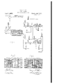
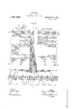
- Figure 1 is a diagrammatic view of a system of control embodying my invention, the main circuits only being shown;
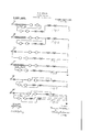
- Figs. 2 and 3 are sequence charts of well-known form indicat ing the sequence of operation of the switches shown in the system of Fig. 1;
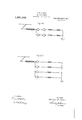
- Fig. l is a diagrammatic view of the auxiliary control circuits for operating the system illustrated in Fig. 1, in accordance with the sequence charts of Figs. 2 and 3;
- Figs. 5 to 10, inclusive, and Figs. 6 and 9 are simple diagrammatic views illustrating various main circuit connections employed in my control system.
- the system here shown comprises a plurality of supply circuits of materially different voltages respectively marked LV-trolley and HV -trolley, signifying the low-voltage and high-voltage portions of the line, which may be insulated from each other by means of a section insulator S1, or in any other suitable manner; a common return circuit, marked Ground, for the two supply circuits, a plurality of electric motors respectively having armatures A1, A2, A3 and A4, corresponding main field windings F1, F2, F 3 and F4: and auxiliary field magnet windings X1, X2, X3 and X4; a plurality of line switches LS1, LS2 and LS3, preferably of a familiar electropneumatically operated type; a plurality of resistor sections, one of which is adapted to be short circuited by a similar switch R1, two of which may be short circuited by a switch R2, and so forth, up to a switch R71, which is
- auxiliary control system shown comprises a master controller MC, which, when moved in one direction, is adapted to connect the motors to the supply circuit of higher voltages and, when moved in the other direction, is adapted to connect them to the supply circuit of lower voltage, the controller being arranged to assume a plu rality of positions a to in, inclusive, and a" to is, inclusive, in the respective directions, to energize the magnet coils of the various circuit-changing switches by means of a suitable battery B, and in accordance with the sequence chart of Figs. 2 and 3.
- the operation of the master controller MG is simple and well understood by those skilled in the art and, consequently, only a brief description thereof is deemed necessary.
- a control circuit is established from one side of the battery B through control finger T to the movable contact members of the controller and thence through the control fingers LS1, LS2, 1' to 6, inclusive, and 21 to the energizing coils of the switches LS1, LS2, 1 to 6, inclusive, and 21 respectively, whereby the motors are disposed in series-circuit relation across the supply circuit of higher voltage with all of the resistors in series with the motors.
- the main circuit connections are indicated in Fig. 5.
- the master controller is operated in the reverse direction from that just described.
- switches LS1, LS2, 1, 21, 3, 4, 6, 7, 8, 9 and R2 are closed, whereby the motors are connected in series parallel relationwith a certain amount of resistance in circuit, as indicated in Fig. 8.
- switches 11, 12, l t and 15 are closed, thereby disposing the motors in parallel relation with a predetermined amount of resistance in common series-circuit relation to the motors. See Fig. 9
- the motor circuit comprises four groups of either two armatures or two field windings.
- the motors are initially disposed in series-circuit relation, one pair of the motors, is then short-circuited temporarily, the positive side of the circuit of the short-circuited machine is then connected to the positive side of the remaining motors, the short circuit is then opened and the negative side of the previously short circuited.
- motors is connected to the negative side of the supply circuit, whereby the series-parallel connection of the motors is obtained.
- the motors are initially connected in series-parallel relation.
- a system of control comprising a plurality ojt supply-circuits of materially different voltages, a plurality of electric motors severally provided with armatures and field magnet windings, and switching means for connecting said motors to either of said supply circuits initially inseries or seriesparallel and subsequently in series-parallel or parallel circuit relation, according to the supply circuit employed, and for maintaining said field windings on a predetermined side of all the armatures throughout the operation of the motors.
- a system of control comprising a plurality of supply circuits of materially different voltages, a plurality of electric motors severally provided with armatures and field magnet windings, and switching means for connecting said motors to any one of: said supply circuits for series-parallel operation, for maintaining said field windings adapted for direct coiniection to the ground side of the employed supply circuit throughout the operation of the motors and for maintaining the circuit through a portion of said motors uninterrupted.
- a system of control comprising a plurality of supply circuits of materially dittt'crent voltages, a plurality of electric motors severally provided with armatures and field magnet windings, and switching means for connecting said motors to either of said supply circuits initially in series or series-parallel and subsequently in series-parallel or parallel circuit relation, according to the supply circuit employed, and for maintaining said field windings adapted for direct connection to the ground side of the employed supply circuit throughout the operation of the motors.
- a system of control comprising a plurality of supply circuits, the voltage of one of which is substantially twice that of the other. tour electric motors severally provided with armatures and field magnet Windings, and controlling means for connecting said motors to either of said supply circuits initiallv in series or series-parallel and subsequently in series-parallel or parallel circnit relation, according to the supply circuit employed, and for maintaining said field windings on the ground side of the several armatures throughout the operation of the motors.
- a system of control comprising a plurality of supply circuits of materially diiter- I cut voltages, a plurality of electric motors severally provided with armatnres and field magnet windings, and means for connecting said motors to said supply circuits initially in series or series-parallel circuit relation,
- said means being adapted, when connected to one of said supply circuits, to subsequently connect the motors in seriesparallel relation, and being adapted, when connected to the other supply circuit, to sul sequently connect the motors in parallel relation, the field winding connections being adapted to maintain the windings on the ground side of the several arinatures throughout either complete operation of the motor.
- a system 01" control comprising a plucircuit, to subsequently connect each armature and its corresponding field winding in parallel-circuit relatlon with each of the other associated armatures and field w1ndings, the field winding connections being adapted to maintain the windings on the ground side of the several armatures throughout either complete operation of the motors.
- a system of control comprising a plurality of supply circuits, the voltage of one of which is substantially twice that of the other, an electric motor circuit embodying four pairs of armatures and field magnet windings, switching means for connecting the motors to said supply circuits initially in series or series-parallel circuit relation, respectively, other switching means for subsequently connecting two adjacent seriesconnected pairs of armatures and field windings in parallel-circuit relation with the remaining two pairs when one of the supply circuits is employed, and other switching means for subsequently connecting each armature and its corresponding field windings in parallel-circuit relation with each of the other associated armatures and field windings when the other supply circuit is employed, the switching means connected to the field windings being adapted to mainr&
- a system of control comprising a plurality of supply circuits, the Voltage of one of which is substantially twice that of the other, an electric motor circuit embodying four pairs of armatures and field magnet windings, switching means for connecting the motors to one of said supply circuits with the field windings initially in seriescircuit relation with all the motor armatures, subsequently temporarily short-circuiting one pair of armatures and the corresponding field windings, connecting the positive side of the circuit of the short-circuited machines to the positive side of the remaining niotors, opening the short-circuit and connecting the ground side of the previously short-circuited motors to the ground side of the employed supply circuit, whereby the motors are connected in series-parallel cir cuit relation and switching means for connecting the motors to the other supply circuit initially in series-parallel circuit relation, each pair of motors having the armatures and field windings respectively grouped together, connecting the ground side of one of each pair of armatures to the positive side of the corresponding field winding, subsequently opening
Landscapes
- Engineering & Computer Science (AREA)
- Power Engineering (AREA)
- Control Of Multiple Motors (AREA)
Description
N. W. STORER.
CONTROL SYSTEM.
APPLICATION FILED MAY 11, 9x4.
Patented July 3, 1917.
4 SHEETS-SHEET I.
5867119066 0f .fwifches /200 1 0/73.
Sequence of Swifc/vps -24100 Va/fa INVENTOR Wow/w ATTORNEY N- W. STORER.
CONTROL SYSTEM.
APPLICATION FILED MAY 11, 1914.
Patented July 3, 1917.
4 SHEETSSHEET 2.
0000000OOOOOOOOOOOOOOOOOO mm awp WITNESSES L5 /L52L531 212 J 4 00000DOOOQOOOQOOQOQOOOOODOOO INVENTOR MM w BY WW ATTORNEY N. W. STORER.
CONTROL SYSTEM.
APPLICATION. FILED MAY1],I9|4- l,231,663. Patented July 3, 191?.
4 SHEETS-SHEET 3.
M 5 0 l ITNE SE81 INVENTO 72W mm.
N. W. STORER.
CONTROL SYSTEM.
APPLICATION FILED MAY 11. 1914- 1,231,663. Patented July 3, 1917.
4 SHEETSSHEET 4 WITNESSES:
INVENTOR fl wmm W f/are/ BY W z MM ATTORNEY UNITED STATES PATENT OFFICE.
NORMAN W. STORER, OF PITTSBURGH, PENNSYLVANIA, ASSIGNOR TO WESTINGHOUSE ELECTRIC AND MANUFACTURING COMPANY, A CORPORATION OF PENNSYLVANIA.
CONTROL SYSTEM.
Application filed May 11, 1914.
To all whom it may concern:
Be it known that I, NORMAN lV. STORER, a citizen of the United States, and a resident of Pittsburgh, in the county of Allegheny and State of Pennsylvania. have invented a new and useful Improvement in Control Systems, of which the following is a specification.
My invention relates to control systems for electric motors and it has special reference to control systems that are adapted for employment in high-voltage, direct-current electric railway service.
The object of my invention is to provide, in a system of the above-indicated character, means for permitting the operation of the motors from a plurality of supply circuits of materially different voltages and maintaining the field winding on the ground side of the several armatures throughout the operation, whereby minimum voltage strains are imposed on the field windings, thus obviating the necessity of extra insulation of the field coils and reducing the liability of grounding on the motor frames to a great extent.
More specifically stated, the object of my invention is to provide a system of control whereby the motors may be operated from either of two supply circuits, one of which may have a voltage of 2&00 and the other 1200 volts, for example, and whereby the motors, when connected to the high-voltage circuit, are initially in series relation and are subsequently disposed in series-parallel relation, and, when connected to the lowvoltage supply circuit, are initially in seriesparallel circuit relation and are later connected in full parallel, the field windings of all the motors being maintained on the ground side of all the armatures throughout either complete operation.
Another object of my invention is to provide a system for accomplishing the abovementioned objects with a minimum number of switches and a minimum number of circuit changes.
I am aware that, in a broad sense, systems embodying the maintenance of the field windings of aplurality of electric motors on the ground side of the corresponding ar matures have been employed heretofore. My invention, therefore, comprises a combination of a plurality of supply circuits of ma- Specification of Letters Patent.
Patented J ul'y 3, 1917.
Serial No. 837,700.
terially different voltages, means for operating a plurality of motors from either circuit, according to whether the electric vehicle is running in interurban or city service, for example, and means for maintaining the field windings on the ground side of the armatures in both cases, a minimum number of switches being employed in the system for accomplishing the desired circuit changes.
In the accompanying drawing, Figure 1 is a diagrammatic view of a system of control embodying my invention, the main circuits only being shown; Figs. 2 and 3 are sequence charts of well-known form indicat ing the sequence of operation of the switches shown in the system of Fig. 1; Fig. l is a diagrammatic view of the auxiliary control circuits for operating the system illustrated in Fig. 1, in accordance with the sequence charts of Figs. 2 and 3; and Figs. 5 to 10, inclusive, and Figs. 6 and 9, are simple diagrammatic views illustrating various main circuit connections employed in my control system.
Referring to Fig. 1 of the drawing, the system here shown comprises a plurality of supply circuits of materially different voltages respectively marked LV-trolley and HV -trolley, signifying the low-voltage and high-voltage portions of the line, which may be insulated from each other by means of a section insulator S1, or in any other suitable manner; a common return circuit, marked Ground, for the two supply circuits, a plurality of electric motors respectively having armatures A1, A2, A3 and A4, corresponding main field windings F1, F2, F 3 and F4: and auxiliary field magnet windings X1, X2, X3 and X4; a plurality of line switches LS1, LS2 and LS3, preferably of a familiar electropneumatically operated type; a plurality of resistor sections, one of which is adapted to be short circuited by a similar switch R1, two of which may be short circuited by a switch R2, and so forth, up to a switch R71, which is adapted to short-circuit all of the resistor sections; a plurality of motor-operating switches 21, and 1 to 15, inclusive; and a plurality of reversing switches, marked RS, that are severally associated with the main field windings of the various motors.
deference may now be had to Fig. l, in
which the auxiliary control system shown comprises a master controller MC, which, when moved in one direction, is adapted to connect the motors to the supply circuit of higher voltages and, when moved in the other direction, is adapted to connect them to the supply circuit of lower voltage, the controller being arranged to assume a plu rality of positions a to in, inclusive, and a" to is, inclusive, in the respective directions, to energize the magnet coils of the various circuit-changing switches by means of a suitable battery B, and in accordance with the sequence chart of Figs. 2 and 3.
The operation of the master controller MG is simple and well understood by those skilled in the art and, consequently, only a brief description thereof is deemed necessary.
Assuming the master controller to be moved to its initial position a, for operation of the motors from the supply circuit of higher voltage, a control circuit is established from one side of the battery B through control finger T to the movable contact members of the controller and thence through the control fingers LS1, LS2, 1' to 6, inclusive, and 21 to the energizing coils of the switches LS1, LS2, 1 to 6, inclusive, and 21 respectively, whereby the motors are disposed in series-circuit relation across the supply circuit of higher voltage with all of the resistors in series with the motors. The main circuit connections are indicated in Fig. 5.
In positions Z) to 7, inclusive, of the master controller, certain of the resistor switches are closed in accordance with familiar practice and as indicated by the dotted lines in Fig. 5. The operation may be readily fol.-
. lowed, inasmuch as each control finger is designated by priming the reference character of the corresponding switch. Two sections of the resistors Bet and R6 remain in circuit throughout the operation of the motors for the purpose of reducing the'eflect of surges in line voltage and other abnormal conditions, as will be understood. During transition of themotors from series to seriesparallel relation, all the resistor switches except R1, are opened and theswitch I is simultaneously closed, thereby giving the connections shown in Fig. 6, in which one pair'of the motors and the corresponding field windings are temporarily shortcircuited. The switches 2' and are then opened and switches 8 and 9 are closed as soon as the controller occupies its position g. See Fig. G Q The switches are again successively closed, with the exception of switches R4: and R6, and in the final. running position 715, the connections of the. motors are as illustrated in Fig. 7.
hen the motors are to be operated from the supply circuit of lower voltage, the master controller is operated in the reverse direction from that just described. In position a, switches LS1, LS2, 1, 21, 3, 4, 6, 7, 8, 9 and R2 are closed, whereby the motors are connected in series parallel relationwith a certain amount of resistance in circuit, as indicated in Fig. 8.
In positions I) to f, inclusive, the resistors in circuit are gradually excluded, with the exception of the resistor corresponding to the switch R1, which remains in the motor circuit for a regulating purpose, similar to that hereinbet'ore described in connection with the operation from the supply circuit of higher voltage.
During the transition from series-parallel to parallel, the resistor switches are first opened, and switches 10 and 13 are then closed. Switches 21," 3, l and 6 are next opened, thereby giving the motor connections of Fig. 9, in which only two motors are operative.
In position 9, switches 11, 12, l t and 15 are closed, thereby disposing the motors in parallel relation with a predetermined amount of resistance in common series-circuit relation to the motors. See Fig. 9
In the positions it to 7;", inclusive, the resistors are gradually excluded, in a manner similar to that hereinbetore described, and, in the final running'position 7r only, resistors R1 and R2 remain in circuit. The con ncctions are illustrated in F ig. 10.
It will thusbe observed that the motor circuit comprises four groups of either two armatures or two field windings. In operation from the circuit of higher voltage, the motors are initially disposed in series-circuit relation, one pair of the motors, is then short-circuited temporarily, the positive side of the circuit of the short-circuited machine is then connected to the positive side of the remaining motors, the short circuit is then opened and the negative side of the previously short circuited. motors is connected to the negative side of the supply circuit, whereby the series-parallel connection of the motors is obtained. lVhen operating from the circuit of low voltage, the motors are initially connected in series-parallel relation. The negative, that is to say, ground side of one of each of the pairs of armatures is then connected to the positive side of the corresponding field winding. the circuit between the respective pairs of armatures and of field windings is opened, and then the positive side of the remaining armatures is connected to the positive side of the first set of armatures and the 5 ground side ofthe remaining field windings is connected to the ground side of the employed supply circuit, whereby the motors are disposed in full parallel relation. Throughout the operation from either the high-voltage or the low-voltage circuit, it
will be observed that the field magnet windings are maintained on the ground side of the armatures, for a purpose hereinbetore specified.
I do not wish to be restricted to the specific circuit connections or arrangement of parts herein set forth, but intend that only such limitations shall be imposed as are indicated in the appended claims, wherein I desire it to be understood that the term negative refers to the side of the winding in question that is nearer to the ground side of the supply circuit, it being usual practice to connect the negative side to ground.
I claim as my invention:
l. A system of control comprising a plurality ojt supply-circuits of materially different voltages, a plurality of electric motors severally provided with armatures and field magnet windings, and switching means for connecting said motors to either of said supply circuits initially inseries or seriesparallel and subsequently in series-parallel or parallel circuit relation, according to the supply circuit employed, and for maintaining said field windings on a predetermined side of all the armatures throughout the operation of the motors.
2. A system of control comprising a plurality of supply circuits of materially different voltages, a plurality of electric motors severally provided with armatures and field magnet windings, and switching means for connecting said motors to any one of: said supply circuits for series-parallel operation, for maintaining said field windings adapted for direct coiniection to the ground side of the employed supply circuit throughout the operation of the motors and for maintaining the circuit through a portion of said motors uninterrupted.
3. A system of control comprising a plurality of supply circuits of materially dittt'crent voltages, a plurality of electric motors severally provided with armatures and field magnet windings, and switching means for connecting said motors to either of said supply circuits initially in series or series-parallel and subsequently in series-parallel or parallel circuit relation, according to the supply circuit employed, and for maintaining said field windings adapted for direct connection to the ground side of the employed supply circuit throughout the operation of the motors.
a. A system of control comprising a plurality of supply circuits, the voltage of one of which is substantially twice that of the other. tour electric motors severally provided with armatures and field magnet Windings, and controlling means for connecting said motors to either of said supply circuits initiallv in series or series-parallel and subsequently in series-parallel or parallel circnit relation, according to the supply circuit employed, and for maintaining said field windings on the ground side of the several armatures throughout the operation of the motors.
A system of control comprising a plurality of supply circuits of materially diiter- I cut voltages, a plurality of electric motors severally provided with armatnres and field magnet windings, and means for connecting said motors to said supply circuits initially in series or series-parallel circuit relation,
respectively, said means being adapted, when connected to one of said supply circuits, to subsequently connect the motors in seriesparallel relation, and being adapted, when connected to the other supply circuit, to sul sequently connect the motors in parallel relation, the field winding connections being adapted to maintain the windings on the ground side of the several arinatures throughout either complete operation of the motor.
6. A system 01": control comprising a plucircuit, to subsequently connect each armature and its corresponding field winding in parallel-circuit relatlon with each of the other associated armatures and field w1ndings, the field winding connections being adapted to maintain the windings on the ground side of the several armatures throughout either complete operation of the motors.
7. A system of control comprising a plurality of supply circuits, the voltage of one of which is substantially twice that of the other, an electric motor circuit embodying four pairs of armatures and field magnet windings, switching means for connecting the motors to said supply circuits initially in series or series-parallel circuit relation, respectively, other switching means for subsequently connecting two adjacent seriesconnected pairs of armatures and field windings in parallel-circuit relation with the remaining two pairs when one of the supply circuits is employed, and other switching means for subsequently connecting each armature and its corresponding field windings in parallel-circuit relation with each of the other associated armatures and field windings when the other supply circuit is employed, the switching means connected to the field windings being adapted to mainr&
tain the windings on the ground side of the several armatures throughout either complete operation of the motors. V
8. A system of control comprising a plurality of supply circuits, the Voltage of one of which is substantially twice that of the other, an electric motor circuit embodying four pairs of armatures and field magnet windings, switching means for connecting the motors to one of said supply circuits with the field windings initially in seriescircuit relation with all the motor armatures, subsequently temporarily short-circuiting one pair of armatures and the corresponding field windings, connecting the positive side of the circuit of the short-circuited machines to the positive side of the remaining niotors, opening the short-circuit and connecting the ground side of the previously short-circuited motors to the ground side of the employed supply circuit, whereby the motors are connected in series-parallel cir cuit relation and switching means for connecting the motors to the other supply circuit initially in series-parallel circuit relation, each pair of motors having the armatures and field windings respectively grouped together, connecting the ground side of one of each pair of armatures to the positive side of the corresponding field winding, subsequently opening the circuit between the respective pairs of armatures and of field windings, connecting the positive sides of the remaining armatures to the positive side of the first, and connecting the ground side of the remaining field windings to the ground side of the employed supply circuit, whereby the motors are connected in parallel-circuit relation, the switching means connected to the field windings being adapted to maintain the windings on the ground side of the several armatures throughout either complete operation of the motors.
In testimony whereof, I have hereunto subscribed my name this 18th day of Apr,
NORMAN XV. STORER. Witnesses JACOB STAIR, Jr., B. B. HINEs.
Copies 01 this patent may be obtained for five cents each, by addressing the Commissioner of latents,
Washington, D. G.
Priority Applications (1)
| Application Number | Priority Date | Filing Date | Title |
|---|---|---|---|
| US83770014A US1231663A (en) | 1914-05-11 | 1914-05-11 | Control system. |
Applications Claiming Priority (1)
| Application Number | Priority Date | Filing Date | Title |
|---|---|---|---|
| US83770014A US1231663A (en) | 1914-05-11 | 1914-05-11 | Control system. |
Publications (1)
| Publication Number | Publication Date |
|---|---|
| US1231663A true US1231663A (en) | 1917-07-03 |
Family
ID=3299504
Family Applications (1)
| Application Number | Title | Priority Date | Filing Date |
|---|---|---|---|
| US83770014A Expired - Lifetime US1231663A (en) | 1914-05-11 | 1914-05-11 | Control system. |
Country Status (1)
| Country | Link |
|---|---|
| US (1) | US1231663A (en) |
Cited By (1)
| Publication number | Priority date | Publication date | Assignee | Title |
|---|---|---|---|---|
| US2525296A (en) * | 1946-06-26 | 1950-10-10 | Forges Ateliers Const Electr | Electric traction equipment |
-
1914
- 1914-05-11 US US83770014A patent/US1231663A/en not_active Expired - Lifetime
Cited By (1)
| Publication number | Priority date | Publication date | Assignee | Title |
|---|---|---|---|---|
| US2525296A (en) * | 1946-06-26 | 1950-10-10 | Forges Ateliers Const Electr | Electric traction equipment |
Similar Documents
| Publication | Publication Date | Title |
|---|---|---|
| US1231663A (en) | Control system. | |
| US1267916A (en) | System of control. | |
| US1506754A (en) | Motor-control system | |
| US1336562A (en) | System of control | |
| US967387A (en) | System of control for alternating-direct-current motors. | |
| US1266607A (en) | Control system. | |
| US1189292A (en) | Control system. | |
| US1126198A (en) | Control system for electric motors. | |
| US1266586A (en) | System of control. | |
| US1246421A (en) | Control system. | |
| US1245397A (en) | Regenerative control. | |
| US671491A (en) | System of train control. | |
| US1236778A (en) | Control system. | |
| US806752A (en) | Combined alternating and direct current control apparatus. | |
| US904780A (en) | System of control. | |
| US870147A (en) | Multiple-unit-controlling system for electric locomotives or motor-cars. | |
| USRE13115E (en) | goopee | |
| US1268052A (en) | System of control. | |
| US1280990A (en) | System of control. | |
| US1245396A (en) | System of control. | |
| US912995A (en) | Electric-motor-control system. | |
| US673531A (en) | Electric-railway controller. | |
| US832926A (en) | Multiple-unit switch-control system. | |
| US1246425A (en) | System of control. | |
| US1204432A (en) | Control system for electric motors. |