US12313380B2 - Protective mantel and accessory hub - Google Patents
Protective mantel and accessory hub Download PDFInfo
- Publication number
- US12313380B2 US12313380B2 US17/737,202 US202217737202A US12313380B2 US 12313380 B2 US12313380 B2 US 12313380B2 US 202217737202 A US202217737202 A US 202217737202A US 12313380 B2 US12313380 B2 US 12313380B2
- Authority
- US
- United States
- Prior art keywords
- guard
- primary yoke
- accessory hub
- deltoid
- protective mantle
- Prior art date
- Legal status (The legal status is an assumption and is not a legal conclusion. Google has not performed a legal analysis and makes no representation as to the accuracy of the status listed.)
- Active, expires
Links
Images


Classifications
-
- F—MECHANICAL ENGINEERING; LIGHTING; HEATING; WEAPONS; BLASTING
- F41—WEAPONS
- F41H—ARMOUR; ARMOURED TURRETS; ARMOURED OR ARMED VEHICLES; MEANS OF ATTACK OR DEFENCE, e.g. CAMOUFLAGE, IN GENERAL
- F41H1/00—Personal protection gear
- F41H1/02—Armoured or projectile- or missile-resistant garments; Composite protection fabrics
-
- A—HUMAN NECESSITIES
- A41—WEARING APPAREL
- A41D—OUTERWEAR; PROTECTIVE GARMENTS; ACCESSORIES
- A41D13/00—Professional, industrial or sporting protective garments, e.g. surgeons' gowns or garments protecting against blows or punches
- A41D13/0002—Details of protective garments not provided for in groups A41D13/0007 - A41D13/1281
- A41D13/0005—Joints
-
- F—MECHANICAL ENGINEERING; LIGHTING; HEATING; WEAPONS; BLASTING
- F41—WEAPONS
- F41H—ARMOUR; ARMOURED TURRETS; ARMOURED OR ARMED VEHICLES; MEANS OF ATTACK OR DEFENCE, e.g. CAMOUFLAGE, IN GENERAL
- F41H5/00—Armour; Armour plates
- F41H5/013—Mounting or securing armour plates
Definitions
- FIG. 1 is a front view of the body armor system.
- FIG. 2 is a rear view of the body armor system.
- FIG. 3 is a front isometric view of the body armor system.
- FIG. 4 is a right side view of the body armor system.
- FIG. 5 is a rear isometric view of the body armor system.
- FIG. 6 is a front view of the body armor system without the shoulder suspension members.
- FIG. 7 is a rear view of the body armor system without the shoulder suspension members.
- FIG. 8 is a front view of the upper protector.
- FIG. 9 is a rear view of the upper protector.
- FIG. 10 is another rear view of the upper protector.
- FIG. 11 is yet another rear view of the upper protector.
- FIG. 12 is a side view of the upper protector.
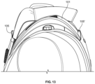
- FIG. 13 is a side view of the upper protector with the shoulder suspension members inserted therein.
- FIG. 14 is an isometric view of the upper protector with the shoulder suspension members inserted therein.
- FIG. 15 is an isometric view of the upper protector with the throat guard removed.
- FIG. 16 shows a step of the insertion of the throat guard into the upper protector.
- FIG. 17 shows another step of the insertion of the throat guard into the upper protector.
- FIG. 18 shows yet another step of the insertion of the throat guard into the upper protector.
- FIG. 19 is an isometric view of the upper protector with the throat guard installed.
- FIG. 20 shows a lateral expansion feature of the upper protector.
- FIG. 21 shows a lateral expansion feature of the upper protector.
- FIG. 22 is a front view of a deltoid guard.
- FIG. 23 is a rear view of the deltoid guard showing an open seam line for the insertion of body armor.
- FIG. 24 shows the attachment of an identification panel onto the deltoid guard.
- FIG. 25 shows the attachment of an identification panel onto the deltoid guard.
- FIG. 26 shows the attachment of an identification panel onto the deltoid guard.
- FIG. 27 shows the attachment of the deltoid guard to the upper protector.
- FIG. 28 shows the attachment of the deltoid guard to the upper protector.
- FIG. 29 shows the upper protector with the deltoid guard attached thereto.
- FIG. 30 shows the upper protector with the deltoid guard attached thereto.
- FIG. 31 shows the upper protector with the deltoid guard attached thereto.
- FIG. 32 is a front isometric view of the armor carrier.
- FIG. 33 is a rear isometric view of the armor carrier.
- FIG. 34 is a side view of the armor carrier.
- FIG. 35 shows a front accessory panel to be attached to the armor carrier.
- FIG. 36 shows the attachment of the front accessory panel to the armor carrier.
- FIG. 37 shows the insertion of attachment members of the front accessory panel into corresponding openings on the armor carrier.
- FIG. 38 shows the insertion of attachment members of the front accessory panel into corresponding openings on the armor carrier.
- FIG. 39 shows the insertion of attachment members of the front accessory panel into corresponding openings on the armor carrier.
- FIG. 40 the closed state of a zippered pouch of the armor carrier in which armor is inserted and retained.
- FIG. 41 shows the open state of a zippered pouch of the armor carrier in which armor is inserted and retained.
- FIG. 42 shows a modular accessory system on the sides of the armor carrier.
- FIG. 43 shows a bicep protector
- a body armor system comprising an armor carrier 200 disposed over an upper protector 100 .
- the upper protector is also referred to herein as a mantel and/or accessory hub.
- the upper protector is disposed over the shoulders and provides protection for the upper shoulders and neck area of the wearer.
- the upper protector also provides structure to comfortably retain the weight of the carrier across the shoulders and upper body of the wearer.
- the upper protector includes shoulder suspension members 101 inserted into openings on the anterior and posterior of the upper protector, about the shoulder area, which assist in supporting the weight of the armor carrier 200 .
- a deltoid guard 110 is attached to either or both sides of the upper protector.
- the armor carrier 200 is disposed over the upper protector 100 , resting on the shoulders of the wearer and generally protects the thorax of the wearer.
- the system uses combinations of soft and hard armor to provide protection against blunt objects, sharp objects, ballistics, and fragmentation.
- the mantel includes a primary yoke 102 which comprises the supporting structure of the protector that drapes at least partially over the thorax (upper back and upper chest) of the wearer.
- the yoke 102 retains a throat guard 104 which is inserted at its edges into corresponding openings on the yoke 102 .
- a sliding attachment point 103 At the center of either or both of the front and back of the yoke 102 is a sliding attachment point 103 .
- the sliding attachment point 103 disposed on the central panel 108 of the yoke 102 .
- the attachment point 103 comprises hook and loop fastener or another removable fastener such as a snap or buckle which engages a corresponding attachment point on the inside of the armor carrier 200 .
- the attachment point 103 is configured to slide in a vertical direction along the upper protector 100 in order to allow the armor carrier 200 to articulate relative to the upper protector 100 to maximize comfort and mobility for the wearer.
- openings 105 which receive the shoulder suspension member 101 as further shown and described herein.
- hook and loop fastener 106 is provided at the top of the shoulder area which is configured to engage corresponding shoulder straps of the armor carrier 200 in certain configurations. Also show are front and rear openings 105 and 105 ′ which receive the ends of the shoulder suspension member 101 as shown in FIG. 10 .
- the shoulder suspension member 101 is a removable, semi-rigid support that helps distribute the load across the wearers shoulders caused by the weight of the armor carrier 200 when the carrier is installed over the upper protector 100 . As shown, for example in FIG. 13 , in some embodiments, at least a portion of the shoulder suspension member 101 is raised above the surface of the yoke 102 .
- the mantel and accessory hub 100 is configured to function as a primary point of attachment of various accessories, including those described herein such as the throat guard and deltoid/bicep protectors so that the system functions in a modular manner and avoids the need to move such accessories back and forth between bulkier armor carriers.
- the mantel and accessory hub 100 is intended to be worn underneath an armor carrier or plate carrier while retaining the desired accessories to allow for selective use of a desired armor carrier without having to reposition or re-attach the accessories to that armor carrier.
- the mantel and accessory hub 100 does not include hard armor, i.e. rigid plates.
- the mantel and accessory hub 100 does not include pockets that would otherwise be designed to intended to receive hard armor.
- the primary yoke 102 covers only the thorax (upper back and upper chest area) of the wearer and, in some embodiments, does not extend to cover the abdomen, lower abdomen, middle back, or lower back areas of the wearer.
- the functionality of the removable throat guard 104 is shown.
- the throat guard 104 is completely removed from the upper protector 100 .
- the throat guard 104 is generally V-shaped with two upper horns that is received into the collar 107 of the upper protector 100 and a bottom portion that is received into a central panel 108 of the upper protector 100 .
- the central panel 108 comprises or includes a pocket (where 108 points) to receive the bottom portion of the throat guard 104 .
- FIG. 19 shows the throat guard 104 in its fully installed position.
- FIGS. 20 - 21 depict a lateral expansion feature of the upper protector which aids in the comfort and mobility of the wearer. Shown is the front of the yoke 102 with the central panel 108 disposed between the respective sides 116 and 116 ′ at the front of the yoke 102 . In this way, it is shown that, in some embodiments, the yoke 102 comprises one-piece element covering the thorax of the wearer except for an opening delimited by the respective sides 116 and 116 ′ which, in some embodiments are disposed at the front of the yoke 102 (See FIG. 21 ).
- a resilient elastic material 109 which allows the sides 116 and 116 ′ of the yoke 102 to expand and contract relative to the central panel 108 .
- the central panel 108 is suspended by the resilient elastic material in the opening delimited by the respective sides 116 and 116 ′. This expansion feature also aids the wearer in donning or doffing the upper protector or mantel and/or accessory hub 100 by providing more room and adjustability.
- the resilient elastic material 109 could be substituted for a zipper or other expandable/contractable closure to assist the wearer in putting on and taking off the upper protector 100 .
- FIG. 22 is a front view of the deltoid guard 110 , which has a generally triangular or trapezoidal shape and, in some embodiments, has one or more openings 111 which receive an identification panel 112 .
- the interior of the deltoid guard 110 is configured to receive and retain soft armor, hard armor, fragmentation armor, or combinations thereof.
- an expandable element 113 such as an elastic strap which retains the guard against the arm of the wearer.
- the identification panel 112 may be reversible and printable and may also include hook and loop fastener for additional adhesion to the deltoid guard 110 . In some embodiments, however, hook and loop fastener is obviated due to the insertions of the corners or edges of the identification panel 112 into one or more corresponding openings 111 on the deltoid guard.
- the identification panel 112 can also be attached elsewhere on the body armor system.
- FIGS. 27 - 28 depict the attachment of the deltoid guard 110 to the upper protector 100 .
- a small removable fastener 114 such as a buckle is attached at the shoulder area of the upper protector 100 which receives a corresponding fastener attached to the top of the deltoid guard 110 .
- the deltoid guard 110 may be fixed to the upper protector 100 .
- an elastic material 115 may be provided at the connection to facilitate expansion and articulation of the deltoid guard 110 with respect to the upper protector 100 to aid wearer comfort.
- FIGS. 29 - 31 show various views the upper protector with the deltoid guard attached thereto.
- the deltoid guard 110 is relatively smaller than traditional designs and does not protect the bicep area in order to enhance mobility.
- a supplemental bicep guard 110 ′ may be implemented, which attaches to the deltoid such that the bicep guard can articulate with respect to the deltoid guard.
- the bicep guard 110 ′ is disposed at least partially underneath the deltoid guard 110 and attaches either to the deltoid guard or the upper protector by a buckle, elastic, and/or wedge received in an opening on the deltoid protector and/or the upper protector. This allows for a modular, scalable arm protection system that maximizes comfort and mobility.
- the armor carrier 200 is configured to work in conjunction with the upper protector 100 , with the armor carrier 200 placed over the upper protector 100 .
- the armor carrier 200 can be used independently from the upper protector 100 in modular fashion as determined by the wearer, the circumstances, and the desired protection.
- the armor carrier 200 includes bi-lateral shoulder straps 207 which attach the front panel 202 to the back panel 203 at the top of the shoulders.
- the shoulder straps 207 of the armor carrier 200 are adjustable by hook and loop fastener or other removable fasteners and the free ends can be tucked into corresponding openings on the front and/or back panels 202 and 203 .
- bi-lateral abdomen straps 201 which attach the front panel 202 to the back panel 203 around the lower thorax or abdomen of the wearer.
- the bi-lateral side straps 201 comprise and/or include an accessory modular accessory system 206 .
- the armor carrier includes an optional font flap 208 and a rear flap 205 which are removably attached to the carrier 200 .
- the rear flap 205 is attached to the armor carrier 200 at the respective shoulder straps 207 by a fastener 204 , such as by a buckle.
- FIGS. 35 - 39 show in a front accessory panel 208 which is removably attached to the front panel 202 of the armor carrier.
- the front accessory panel 208 is configured to easily align and attach to the front panel 202 using magnetic and/or mechanical attachments.
- the inside surface of the flap 208 includes one more magnets 209 which are configured to align and attach to corresponding magnets on the front accessory panel 208 .
- an interior aspect of the accessory panel 208 includes a raised wedge 211 which is received in a corresponding opening on the armor carrier, as shown in FIG. 36 .
- the wedge may be located on the armor carrier with the corresponding opening provided on the accessory panel 208 .
- the top edge of the front accessory panel 208 includes one or more rigid attachment members or fasteners 210 (buckles, clasps, or prongs) that are retained in corresponding openings on the upper portion of the front panel 202 of the armor carrier 200 .
- the rigid attachment member or fastener 210 is configured to enter through an connect with an opening designed to secure accessories, such as a 1′′-1.5′′ opening on the armor carrier 200 or an accessory, a laser cut opening, a MOLLE webbing system-compatible opening. This attachment configuration assures that the front accessory panel 208 is aligned and secured with respect to the front panel 202 for ease of attachment and use.
- FIGS. 37 - 39 depict the insertion of buckles of the front accessory panel into corresponding openings on the armor carrier.
- FIGS. 40 - 41 show the closed and opened state of a pouch 300 at the front panel 202 of the armor carrier in which armor (soft, hard, fragmentation, or the like) is inserted and retained.
- a corresponding pouch is located on the back panel 203 and may also receive and retain armor (soft, hard, fragmentation, or the like).
- the pouches have a zippered opening to provide a much easier means for adding and removing body armor to the carrier in comparison to traditional sleeves and openings which are typically accessed at an interior aspect of a carrier.
- the zippered pouches are configured to extend outward to accommodate curved body armor plates without bunching or discomfort for the wearer.
- the pouches may be configured to be removable from the respective front and back panels of the armor carrier by hook and loop fasteners, wedges or edges received in corresponding openings on the panels, or other releasable fasteners.
- FIG. 42 shows a modular accessory system 206 on the side straps 201 of the armor carrier.
- One or more spaced-apart rows of apertures are provided, which can be used as mounting points for accessories such as sheaths, holsters, and the like, which accessories have corresponding snaps that fit inside the apertures.
- the modular accessory system 206 facilitates the attachment of sliding or moveable accessories.
- the accessories may be attached by any male-female fitting that passes through the apertures.
- the body armor system described herein can be of a multi-material construction.
- the fabrics that face inward toward the wearer or otherwise come in contact with the body of the wearer, such as the collar, are composed of a no-snag pack cloth or nylon material. This avoids snagging on rough skin or facial hair.
- the body armor system utilizes rivets or grommets as a supplement or replacement for bar tacks or other sewing connections to minimize the amount of visible traditional stitching which can snag and otherwise wear out over time. Rivets and grommets also improve manufacturing tolerances and ease of manufacturing in general, as less manual sewing is required and the unit can be more easily built from a template.
- soft body armor refers to a relatively soft and flexible but strong material, such as Kevlar or polyethylene, inserted into or otherwise forming a garment (or portion thereof) worn by a user for protective purposes.
- soft armor is distinguished from hard armor, as referred to herein, the latter typically presented in the form of thick, rigid plates made of firm, durable materials such as ceramic, ceramic composites, polyethylene, fibers, Kevlar, steel, and the like.
- Hard armor plates do not readily deform or otherwise conform to the body of the wearer.
- protective garments utilize a combination of soft and hard armor in order to strike a balance between wearability, comfort, and mobility on the one hand, and maximum protection on the other hand.
- the term “opening” as used herein and in the claims shall be deemed limited as it may refer to any number of slots, slits, apertures, channels, covered areas, or the like. It is to be noticed that the term “comprising,” used in the claims, should not be interpreted as being limitative to the means listed thereafter. Thus, the scope of the expression “a device comprising means A and B” should not be limited to devices consisting only of components A and B. It means that with respect to the present invention, the only relevant components of the device are A and B. Put differently, the terms “including”, “comprising” and variations thereof mean “including but not limited to”, unless expressly specified otherwise.
- a device A coupled to a device B should not be limited to devices or systems wherein an output of device A is directly connected to an input of device B. It means that there exists a path between an output of A and an input of B which may be a path including other devices or means.
- Elements of the invention that are in communication with each other need not be in continuous communication with each other, unless expressly specified otherwise.
- elements of the invention that are in communication with each other may communicate directly or indirectly through one or more other elements or other intermediaries.
Landscapes
- Engineering & Computer Science (AREA)
- General Engineering & Computer Science (AREA)
- Health & Medical Sciences (AREA)
- General Health & Medical Sciences (AREA)
- Physical Education & Sports Medicine (AREA)
- Textile Engineering (AREA)
- Professional, Industrial, Or Sporting Protective Garments (AREA)
- Helmets And Other Head Coverings (AREA)
Abstract
Description
Claims (22)
Priority Applications (5)
| Application Number | Priority Date | Filing Date | Title |
|---|---|---|---|
| US17/737,202 US12313380B2 (en) | 2021-05-05 | 2022-05-05 | Protective mantel and accessory hub |
| US18/350,362 US12560412B2 (en) | 2021-05-05 | 2023-07-11 | Modular accessory system |
| US18/488,097 US12566049B2 (en) | 2021-05-05 | 2023-10-17 | Body armor system |
| US19/181,670 US20250244106A1 (en) | 2021-05-05 | 2025-04-17 | Protective mantel and accessory hub |
| US19/371,640 US20260055994A1 (en) | 2021-05-05 | 2025-10-28 | Accessory system |
Applications Claiming Priority (2)
| Application Number | Priority Date | Filing Date | Title |
|---|---|---|---|
| US202163184603P | 2021-05-05 | 2021-05-05 | |
| US17/737,202 US12313380B2 (en) | 2021-05-05 | 2022-05-05 | Protective mantel and accessory hub |
Related Child Applications (3)
| Application Number | Title | Priority Date | Filing Date |
|---|---|---|---|
| US18/350,362 Continuation US12560412B2 (en) | 2021-05-05 | 2023-07-11 | Modular accessory system |
| US18/488,097 Continuation-In-Part US12566049B2 (en) | 2021-05-05 | 2023-10-17 | Body armor system |
| US19/181,670 Continuation US20250244106A1 (en) | 2021-05-05 | 2025-04-17 | Protective mantel and accessory hub |
Publications (2)
| Publication Number | Publication Date |
|---|---|
| US20230012612A1 US20230012612A1 (en) | 2023-01-19 |
| US12313380B2 true US12313380B2 (en) | 2025-05-27 |
Family
ID=82323638
Family Applications (6)
| Application Number | Title | Priority Date | Filing Date |
|---|---|---|---|
| US17/405,306 Active US11385028B1 (en) | 2021-05-05 | 2021-08-18 | Removable and stowable throat guard |
| US17/412,770 Active US11598611B2 (en) | 2021-05-05 | 2021-08-26 | Combination deltoid and bicep guard |
| US17/737,202 Active 2042-06-17 US12313380B2 (en) | 2021-05-05 | 2022-05-05 | Protective mantel and accessory hub |
| US18/350,362 Active 2042-06-13 US12560412B2 (en) | 2021-05-05 | 2023-07-11 | Modular accessory system |
| US19/181,670 Pending US20250244106A1 (en) | 2021-05-05 | 2025-04-17 | Protective mantel and accessory hub |
| US19/371,640 Pending US20260055994A1 (en) | 2021-05-05 | 2025-10-28 | Accessory system |
Family Applications Before (2)
| Application Number | Title | Priority Date | Filing Date |
|---|---|---|---|
| US17/405,306 Active US11385028B1 (en) | 2021-05-05 | 2021-08-18 | Removable and stowable throat guard |
| US17/412,770 Active US11598611B2 (en) | 2021-05-05 | 2021-08-26 | Combination deltoid and bicep guard |
Family Applications After (3)
| Application Number | Title | Priority Date | Filing Date |
|---|---|---|---|
| US18/350,362 Active 2042-06-13 US12560412B2 (en) | 2021-05-05 | 2023-07-11 | Modular accessory system |
| US19/181,670 Pending US20250244106A1 (en) | 2021-05-05 | 2025-04-17 | Protective mantel and accessory hub |
| US19/371,640 Pending US20260055994A1 (en) | 2021-05-05 | 2025-10-28 | Accessory system |
Country Status (1)
| Country | Link |
|---|---|
| US (6) | US11385028B1 (en) |
Families Citing this family (4)
| Publication number | Priority date | Publication date | Assignee | Title |
|---|---|---|---|---|
| US12566049B2 (en) * | 2021-05-05 | 2026-03-03 | Point Blank Enterprises, Inc. | Body armor system |
| US11385028B1 (en) * | 2021-05-05 | 2022-07-12 | Point Blank Enterprises, Inc. | Removable and stowable throat guard |
| US20250123081A1 (en) * | 2023-10-16 | 2025-04-17 | Point Blank Enterprises, Inc. | Mounting accessory for armor carriers |
| DE102024000228A1 (en) * | 2024-01-25 | 2025-07-31 | Bundesrepublik Deutschland, vertr. durch das Bundesministerium der Verteidigung, vertr. durch das Bundesamt für Ausrüstung, Informationstechnik und Nutzung der Bundeswehr | Modular protective vest system |
Citations (47)
| Publication number | Priority date | Publication date | Assignee | Title |
|---|---|---|---|---|
| US3981027A (en) * | 1975-06-19 | 1976-09-21 | Anderson George C | Football shoulder pad restricter |
| FR2483353A1 (en) | 1980-05-27 | 1981-12-04 | Switlik Richard Jr | MODULAR RESCUE APPARATUS |
| US5060314A (en) * | 1990-04-03 | 1991-10-29 | The United States Of America As Represented By The Secretary Of The Navy | Multi-mission ballistic resistant jacket |
| WO1996024816A1 (en) | 1995-02-06 | 1996-08-15 | Squale (S.A.) | Body armour having permanent positive buoyancy |
| GB2315984A (en) * | 1996-08-09 | 1998-02-18 | Tba Industrial Products Ltd | Garment with covered article suspension. |
| US6029270A (en) | 1999-02-12 | 2000-02-29 | Ost; Lynn Van | Modular, all season multi-compartment clothing with bullet-proof features |
| US20040205881A1 (en) * | 2003-04-16 | 2004-10-21 | David Morrow | Protective athletic equipment |
| US20050086728A1 (en) * | 2003-10-23 | 2005-04-28 | Tobergte Edward H. | Football shoulder pads |
| US20050166303A1 (en) * | 2003-11-10 | 2005-08-04 | Aaron Todd D. | Head and neck protection system |
| US20060143771A1 (en) * | 2004-12-30 | 2006-07-06 | Winkle Christopher S V | Body armor |
| US20070028339A1 (en) * | 2005-08-08 | 2007-02-08 | Carlson Richard A | Deltoid arm protection system for ballistic body armor |
| WO2007146810A2 (en) * | 2006-06-09 | 2007-12-21 | Dovner Edward R | Quick-release mechanism for use with protective garment |
| US20080134419A1 (en) * | 2005-01-07 | 2008-06-12 | Med-Eng Systems Inc. | Protective Garment |
| US20080313793A1 (en) * | 2007-06-19 | 2008-12-25 | Sport Maska Inc. | Protective garment with separate inner and outer shells |
| US20090211000A1 (en) * | 2005-08-22 | 2009-08-27 | Roux Phillip D | Body Armor |
| JP2010255152A (en) | 2009-04-28 | 2010-11-11 | Alpha Giken:Kk | Cold insulator and garment |
| US20110004968A1 (en) * | 2009-07-10 | 2011-01-13 | Arthur Morgan | Flotation Body Armor System |
| US20120174273A1 (en) * | 2004-12-10 | 2012-07-12 | Fstechnology, Llc | Extremity armor |
| CN202364817U (en) | 2011-11-17 | 2012-08-08 | 上海卡莎布兰卡服饰有限公司 | Jacket |
| WO2012113857A1 (en) | 2011-02-24 | 2012-08-30 | Paul Boye Technologies | Protective garment including a removal collar |
| WO2012113875A1 (en) * | 2011-02-24 | 2012-08-30 | Paul Boye Technologies | Garment for protecting a person's trunk, providing improved comfort |
| US20140196203A1 (en) * | 2013-01-14 | 2014-07-17 | FirstSpear, LLC | Modular Armor Supplement Apparatus And System With Silent Fasteners And Adjustability |
| DE202014008697U1 (en) | 2013-12-30 | 2014-11-26 | Power-Bike Gmbh | protector jacket |
| GB2518669A (en) | 2013-09-28 | 2015-04-01 | Toby Evans | Scalable torso armour carrier system (STACS) |
| US20150247705A1 (en) * | 2013-10-01 | 2015-09-03 | Mission Ready Services, Inc. | Integrated Body Armor Garment |
| US9144255B1 (en) * | 2012-02-02 | 2015-09-29 | Armorworks Enterprises LLC | System for attaching accessories to tactical gear |
| US20150282536A1 (en) * | 2012-11-06 | 2015-10-08 | Gk Professional | Protective body armor having a front opening |
| US20150369567A1 (en) * | 2014-06-19 | 2015-12-24 | Revision Military S.A.R.L. | Wearable armor plate assembly |
| KR101615176B1 (en) | 2015-10-28 | 2016-04-25 | (주)대산플랜트 | Armor with attachable and removable bracelet |
| US20160187103A1 (en) * | 2014-07-31 | 2016-06-30 | Phalanx Defense Systems, Llc | Verification of Garment Properties Using Multiple Test Coupons |
| US20160238347A1 (en) * | 2015-02-12 | 2016-08-18 | Blauer Manufacturing Company, Inc. | Ballistic Vest Carrier Cover System with Pouches for Hard Armor Panels |
| US20170082404A1 (en) * | 2015-02-12 | 2017-03-23 | Blauer Manufacturing Company, Inc. | Ballistic Vest Carrier Cover with Pouches for Hard Armor |
| WO2017086800A1 (en) * | 2015-11-16 | 2017-05-26 | Missingen Services As | Protective armour gear |
| US20170307335A1 (en) * | 2016-04-20 | 2017-10-26 | Jacob E. Skifstad | Quick Release System for Accessory Pouches Carried by Ballistic Vest |
| US20180058818A1 (en) * | 2016-08-31 | 2018-03-01 | Tyr Tactical, Llc | Ballistic collar |
| US20180180387A1 (en) * | 2016-12-22 | 2018-06-28 | C.I.A. Miguel Caballero Sas | Body Armor |
| US10274289B1 (en) * | 2016-07-01 | 2019-04-30 | II Billy James Barnhart | Body armor ventilation system |
| US20190323800A1 (en) | 2016-12-23 | 2019-10-24 | BLüCHER GMBH | Protective clothing unit and use thereof |
| US10485272B2 (en) * | 2015-02-12 | 2019-11-26 | Blauer Manufacturing Company, Inc. | Ballistic vest carrier cover with pouches for hard armor |
| US10517336B2 (en) * | 2013-08-23 | 2019-12-31 | Xtech Protective Equipment Llc | Protective equipment |
| US10582731B2 (en) * | 2013-03-15 | 2020-03-10 | Russell Brands, Llc | Protective foam material and pads |
| US10646769B1 (en) * | 2016-04-07 | 2020-05-12 | Nike, Inc. | Discrete shoulder sleeve for a shoulder-pad system |
| US11192018B2 (en) * | 2013-08-23 | 2021-12-07 | Xtech Protective Equipment, Llc | Protective equipment |
| US11272751B2 (en) * | 2016-03-01 | 2022-03-15 | Nicholas Popejoy | Protective headgear, impact diffusing systems and methods |
| US11385028B1 (en) * | 2021-05-05 | 2022-07-12 | Point Blank Enterprises, Inc. | Removable and stowable throat guard |
| US20230079499A1 (en) * | 2021-09-13 | 2023-03-16 | Filip Postolek | Modular sleeve systems |
| US20230160668A1 (en) * | 2021-11-23 | 2023-05-25 | Safe Life Defense, Llc | Body armor panel for use with personal protective vest and system for assembling same |
Family Cites Families (57)
| Publication number | Priority date | Publication date | Assignee | Title |
|---|---|---|---|---|
| US1298618A (en) * | 1918-12-06 | 1919-03-25 | Frank Wloszek | Soldier's armor. |
| US3295235A (en) * | 1965-12-23 | 1967-01-03 | Gabriel G Tauber | Holder |
| US4449251A (en) * | 1981-03-02 | 1984-05-22 | Gauthier Jean Marc | Neck and collarbone protector |
| US4686710A (en) * | 1985-12-17 | 1987-08-18 | Stephen Marston | Sports neck protector |
| US4881529A (en) * | 1988-08-10 | 1989-11-21 | Richard Santos | Neck support collar |
| US4993076A (en) * | 1989-07-21 | 1991-02-19 | Dierickx Edward G | Chest protector |
| FI107998B (en) * | 1997-04-17 | 2001-11-15 | Kari Arto Olavi Viitalahti | Skid player cover |
| US5970513A (en) * | 1997-12-31 | 1999-10-26 | Kocher; Robert William | Multi-piece integrated body armor system (MIBAS) |
| US6098196A (en) * | 1998-09-24 | 2000-08-08 | Logan; Michael | Body armor |
| US6339866B1 (en) * | 1999-05-17 | 2002-01-22 | Vaughn French | Method and apparatus for a removable nametag or insignia |
| CA2328023C (en) * | 2000-12-12 | 2009-04-28 | Bauer Nike Hockey Inc. | Shoulder pads with integral arm protectors |
| US6519782B2 (en) * | 2001-05-01 | 2003-02-18 | Hos Development Corporation | Baseball catcher's chest protector |
| US7861326B2 (en) * | 2002-10-17 | 2011-01-04 | Harty Robert D | Modular neck protection device |
| US7020897B2 (en) * | 2003-07-08 | 2006-04-04 | Eagle Industries Unlimited, Inc. | Cut away vest |
| US6934970B1 (en) * | 2004-04-02 | 2005-08-30 | Globe Manufacturing Co. | Fire protective coat with free-hanging throat tab |
| US7506384B2 (en) * | 2004-09-13 | 2009-03-24 | Riddell, Inc. | Shoulder pad for contact sports |
| US8214929B2 (en) * | 2004-09-13 | 2012-07-10 | Riddell, Inc. | Shoulder pads |
| US20080098500A1 (en) * | 2004-12-10 | 2008-05-01 | Peter Matic | Extremity armor |
| CA2518373C (en) * | 2005-09-08 | 2011-02-01 | Bauer Nike Hockey Inc. | Shoulder pads |
| US20070289045A1 (en) * | 2006-02-08 | 2007-12-20 | Eagle Industries Unlimited, Inc. | Garment and load attachment system |
| US20090282595A1 (en) * | 2006-05-30 | 2009-11-19 | The Board Of Regents For Oklahoma State University | Antiballistic Garment |
| US8370962B2 (en) * | 2007-06-26 | 2013-02-12 | William B. McBride | Rapid doffing vest |
| WO2009017807A1 (en) * | 2007-08-02 | 2009-02-05 | Storms Frederick W Jr | Releasable vest |
| EP2240043B1 (en) * | 2008-01-22 | 2017-05-31 | Vista Outdoor Operations LLC | Releasable vest |
| US20100152636A1 (en) * | 2008-12-12 | 2010-06-17 | Parks Ardith D | Ballistic lumbar support belt |
| US20110010829A1 (en) * | 2009-07-16 | 2011-01-20 | David Malcolm Norman | Combined neck and upper body protective garment |
| WO2011109453A1 (en) * | 2010-03-01 | 2011-09-09 | Kdh Defense Systems, Inc. | Weight distribution and support device and system for an armor vest |
| US12140406B2 (en) * | 2010-06-15 | 2024-11-12 | Tyr Tactical, Llc | Personal tactical system with integrated ballistic frame |
| US10921094B2 (en) * | 2010-06-15 | 2021-02-16 | Tyr Tactical, Llc | Personal tactical system with integrated ballistic frame |
| US20170199011A1 (en) * | 2010-06-15 | 2017-07-13 | Tyr Tactical, Llc | Personal tactical system |
| GB2496781A (en) * | 2010-07-09 | 2013-05-22 | Bae Systems Special Defence Systems Of Pennsylvanis Inc | Modular and scalable soldier's garment |
| US9222757B2 (en) * | 2010-11-30 | 2015-12-29 | Jo Won Seuk | Body armor ballistic plate carrier |
| US20160176175A1 (en) * | 2011-01-19 | 2016-06-23 | Angel Armor Llc | Method of manufacturing a ballistic resistant apparatus using dye diffusion thermal transfer |
| US20130126566A1 (en) * | 2011-04-29 | 2013-05-23 | Jo Won Seuk | Attachment System Substructure and Cummerbund of the Same |
| US8808048B2 (en) * | 2011-05-10 | 2014-08-19 | David G. Kent | Tactical flotation safety system |
| PL3391775T3 (en) * | 2011-08-08 | 2021-12-27 | FirstSpear, LLC | Light modular pocket fastening system |
| US20130081189A1 (en) * | 2011-09-30 | 2013-04-04 | Charlie Wei-Min Chiang | Modular Frame for Supporting Body Armor |
| CA2807099C (en) * | 2012-03-09 | 2020-09-22 | Joe Camillo | Wearable sports guard |
| US9802685B2 (en) * | 2013-11-18 | 2017-10-31 | David G. Kent | Flotation safety system |
| US9737100B2 (en) * | 2014-01-13 | 2017-08-22 | Martinson Industries, LLC | Concealable body armor and combination bag/vest |
| IL231232A0 (en) * | 2014-02-27 | 2014-08-31 | Source Vagabond Systems Ltd | Vest with quick release |
| GB201409842D0 (en) * | 2014-06-03 | 2014-07-16 | Bcb Int Ltd | Body armour with integrated floatation |
| US9901127B2 (en) * | 2014-07-15 | 2018-02-27 | Point Blank Enterprises, Inc. | Quick release fastening system |
| US10631584B2 (en) * | 2014-07-15 | 2020-04-28 | Point Blank Enterprises, Inc. | Apparatus including a quick-release fastener and pull cord |
| US9664481B2 (en) * | 2014-08-07 | 2017-05-30 | 5.11, Inc. | Hexagonal attachment system |
| US10551150B1 (en) * | 2014-09-09 | 2020-02-04 | Jo Won Seuk | Body armor plate |
| US20160138894A1 (en) * | 2014-11-13 | 2016-05-19 | James Theodore Heise | Anti-spalling body armor protection system |
| US10391382B2 (en) * | 2014-12-05 | 2019-08-27 | Schroth Safety Products Gmbh | Head and neck restraint device with dynamic articulation |
| DK3137841T3 (en) * | 2015-07-03 | 2019-07-01 | Tyr Tactical Llc | WOMEN PROTECTION VEST |
| US10222180B2 (en) * | 2016-01-18 | 2019-03-05 | Spencer Tien | Plate carrier |
| US10299570B2 (en) * | 2016-10-04 | 2019-05-28 | Kre8Labs, Inc. | Quick release modular backpack system |
| US11098982B2 (en) * | 2017-03-15 | 2021-08-24 | Tyr Tactical, Llc | Integrated body armor harness system |
| US20200003525A1 (en) * | 2018-06-29 | 2020-01-02 | Point Blank Enterprises, Inc. | Flexible Material With Radial MOLLE Cut Pattern |
| US11109664B2 (en) * | 2018-06-29 | 2021-09-07 | Point Blank Enterprises, Inc. | Flexible material with radial MOLLE cut pattern |
| US10876790B2 (en) * | 2019-01-03 | 2020-12-29 | Curtis Fluellen | Ballistic vest cooling assembly |
| US10871351B2 (en) * | 2019-05-06 | 2020-12-22 | Aardvark | Tactical shoulder garment |
| WO2023183828A2 (en) * | 2022-03-21 | 2023-09-28 | Terra Apparel, Inc. | Lumbar support pouch for ballistic vest |
-
2021
- 2021-08-18 US US17/405,306 patent/US11385028B1/en active Active
- 2021-08-26 US US17/412,770 patent/US11598611B2/en active Active
-
2022
- 2022-05-05 US US17/737,202 patent/US12313380B2/en active Active
-
2023
- 2023-07-11 US US18/350,362 patent/US12560412B2/en active Active
-
2025
- 2025-04-17 US US19/181,670 patent/US20250244106A1/en active Pending
- 2025-10-28 US US19/371,640 patent/US20260055994A1/en active Pending
Patent Citations (48)
| Publication number | Priority date | Publication date | Assignee | Title |
|---|---|---|---|---|
| US3981027A (en) * | 1975-06-19 | 1976-09-21 | Anderson George C | Football shoulder pad restricter |
| FR2483353A1 (en) | 1980-05-27 | 1981-12-04 | Switlik Richard Jr | MODULAR RESCUE APPARATUS |
| US5060314A (en) * | 1990-04-03 | 1991-10-29 | The United States Of America As Represented By The Secretary Of The Navy | Multi-mission ballistic resistant jacket |
| WO1996024816A1 (en) | 1995-02-06 | 1996-08-15 | Squale (S.A.) | Body armour having permanent positive buoyancy |
| GB2315984A (en) * | 1996-08-09 | 1998-02-18 | Tba Industrial Products Ltd | Garment with covered article suspension. |
| US6029270A (en) | 1999-02-12 | 2000-02-29 | Ost; Lynn Van | Modular, all season multi-compartment clothing with bullet-proof features |
| US20040205881A1 (en) * | 2003-04-16 | 2004-10-21 | David Morrow | Protective athletic equipment |
| US20050086728A1 (en) * | 2003-10-23 | 2005-04-28 | Tobergte Edward H. | Football shoulder pads |
| US20050166303A1 (en) * | 2003-11-10 | 2005-08-04 | Aaron Todd D. | Head and neck protection system |
| US20120174273A1 (en) * | 2004-12-10 | 2012-07-12 | Fstechnology, Llc | Extremity armor |
| US20060143771A1 (en) * | 2004-12-30 | 2006-07-06 | Winkle Christopher S V | Body armor |
| US20080134419A1 (en) * | 2005-01-07 | 2008-06-12 | Med-Eng Systems Inc. | Protective Garment |
| US20070028339A1 (en) * | 2005-08-08 | 2007-02-08 | Carlson Richard A | Deltoid arm protection system for ballistic body armor |
| US20090211000A1 (en) * | 2005-08-22 | 2009-08-27 | Roux Phillip D | Body Armor |
| WO2007146810A2 (en) * | 2006-06-09 | 2007-12-21 | Dovner Edward R | Quick-release mechanism for use with protective garment |
| US20080313793A1 (en) * | 2007-06-19 | 2008-12-25 | Sport Maska Inc. | Protective garment with separate inner and outer shells |
| JP2010255152A (en) | 2009-04-28 | 2010-11-11 | Alpha Giken:Kk | Cold insulator and garment |
| US20110004968A1 (en) * | 2009-07-10 | 2011-01-13 | Arthur Morgan | Flotation Body Armor System |
| WO2012113875A1 (en) * | 2011-02-24 | 2012-08-30 | Paul Boye Technologies | Garment for protecting a person's trunk, providing improved comfort |
| WO2012113857A1 (en) | 2011-02-24 | 2012-08-30 | Paul Boye Technologies | Protective garment including a removal collar |
| CN202364817U (en) | 2011-11-17 | 2012-08-08 | 上海卡莎布兰卡服饰有限公司 | Jacket |
| US9144255B1 (en) * | 2012-02-02 | 2015-09-29 | Armorworks Enterprises LLC | System for attaching accessories to tactical gear |
| US20150282536A1 (en) * | 2012-11-06 | 2015-10-08 | Gk Professional | Protective body armor having a front opening |
| US20140196203A1 (en) * | 2013-01-14 | 2014-07-17 | FirstSpear, LLC | Modular Armor Supplement Apparatus And System With Silent Fasteners And Adjustability |
| US10582731B2 (en) * | 2013-03-15 | 2020-03-10 | Russell Brands, Llc | Protective foam material and pads |
| US10517336B2 (en) * | 2013-08-23 | 2019-12-31 | Xtech Protective Equipment Llc | Protective equipment |
| US11192018B2 (en) * | 2013-08-23 | 2021-12-07 | Xtech Protective Equipment, Llc | Protective equipment |
| GB2518669A (en) | 2013-09-28 | 2015-04-01 | Toby Evans | Scalable torso armour carrier system (STACS) |
| US20150247705A1 (en) * | 2013-10-01 | 2015-09-03 | Mission Ready Services, Inc. | Integrated Body Armor Garment |
| DE202014008697U1 (en) | 2013-12-30 | 2014-11-26 | Power-Bike Gmbh | protector jacket |
| US20150369567A1 (en) * | 2014-06-19 | 2015-12-24 | Revision Military S.A.R.L. | Wearable armor plate assembly |
| US20160187103A1 (en) * | 2014-07-31 | 2016-06-30 | Phalanx Defense Systems, Llc | Verification of Garment Properties Using Multiple Test Coupons |
| US20160238347A1 (en) * | 2015-02-12 | 2016-08-18 | Blauer Manufacturing Company, Inc. | Ballistic Vest Carrier Cover System with Pouches for Hard Armor Panels |
| US20170082404A1 (en) * | 2015-02-12 | 2017-03-23 | Blauer Manufacturing Company, Inc. | Ballistic Vest Carrier Cover with Pouches for Hard Armor |
| US10485272B2 (en) * | 2015-02-12 | 2019-11-26 | Blauer Manufacturing Company, Inc. | Ballistic vest carrier cover with pouches for hard armor |
| KR101615176B1 (en) | 2015-10-28 | 2016-04-25 | (주)대산플랜트 | Armor with attachable and removable bracelet |
| WO2017086800A1 (en) * | 2015-11-16 | 2017-05-26 | Missingen Services As | Protective armour gear |
| US20180321017A1 (en) | 2015-11-16 | 2018-11-08 | Missingen Services As | Protective armour gear |
| US11272751B2 (en) * | 2016-03-01 | 2022-03-15 | Nicholas Popejoy | Protective headgear, impact diffusing systems and methods |
| US10646769B1 (en) * | 2016-04-07 | 2020-05-12 | Nike, Inc. | Discrete shoulder sleeve for a shoulder-pad system |
| US20170307335A1 (en) * | 2016-04-20 | 2017-10-26 | Jacob E. Skifstad | Quick Release System for Accessory Pouches Carried by Ballistic Vest |
| US10274289B1 (en) * | 2016-07-01 | 2019-04-30 | II Billy James Barnhart | Body armor ventilation system |
| US20180058818A1 (en) * | 2016-08-31 | 2018-03-01 | Tyr Tactical, Llc | Ballistic collar |
| US20180180387A1 (en) * | 2016-12-22 | 2018-06-28 | C.I.A. Miguel Caballero Sas | Body Armor |
| US20190323800A1 (en) | 2016-12-23 | 2019-10-24 | BLüCHER GMBH | Protective clothing unit and use thereof |
| US11385028B1 (en) * | 2021-05-05 | 2022-07-12 | Point Blank Enterprises, Inc. | Removable and stowable throat guard |
| US20230079499A1 (en) * | 2021-09-13 | 2023-03-16 | Filip Postolek | Modular sleeve systems |
| US20230160668A1 (en) * | 2021-11-23 | 2023-05-25 | Safe Life Defense, Llc | Body armor panel for use with personal protective vest and system for assembling same |
Non-Patent Citations (3)
| Title |
|---|
| Additional removable Ballistic Cloth protection around the shoulders, throat and groin areas; https://contest.techbriefs.com/2017/entries/aerospace-and-defense/7851; Apr. 11, 2022. |
| Shift 360™ scalable plate rack system; https://safariland.com/products/shift-360-scalable-plate-rack-system-shift_360; Apr. 11, 2022. |
| Tactical bulletproof vest—guardian; https://www.hardshell.ae/wpcproduct/tactical-vest-guardian/; Apr. 11, 2022. |
Also Published As
| Publication number | Publication date |
|---|---|
| US20220357132A1 (en) | 2022-11-10 |
| US20250244106A1 (en) | 2025-07-31 |
| US20230012612A1 (en) | 2023-01-19 |
| US20230349672A1 (en) | 2023-11-02 |
| US11385028B1 (en) | 2022-07-12 |
| US20260055994A1 (en) | 2026-02-26 |
| US11598611B2 (en) | 2023-03-07 |
| US12560412B2 (en) | 2026-02-24 |
Similar Documents
| Publication | Publication Date | Title |
|---|---|---|
| US12313380B2 (en) | Protective mantel and accessory hub | |
| US12566049B2 (en) | Body armor system | |
| US7987523B2 (en) | Quick release garment | |
| US6948188B2 (en) | Cutaway vests | |
| US9173473B2 (en) | Shoulder strap retention device and method | |
| US8490212B1 (en) | Quick release garment | |
| US5548843A (en) | Back support with means to secure the belt on the wearer while in an open position | |
| EP1402799B1 (en) | Pack with front pouch and back pouch | |
| EP2741631B2 (en) | Light weight modular pouch attachment system | |
| US9271559B2 (en) | Body armor support harness | |
| US20090070907A1 (en) | Body Armor Carrier Vest | |
| US20230404182A1 (en) | Concealed carry vest with compartment for securing an in-waistband holster | |
| US20030205593A1 (en) | Backpack with integral raingear | |
| WO2019193444A1 (en) | Protective back-pack | |
| US20220316842A1 (en) | Side securement assembly for a garment | |
| CN101072518A (en) | clothing style backpack | |
| US11022402B1 (en) | Printing-reducing strap for use with concealed carry holsters | |
| US20200113316A1 (en) | Wearable outer thigh pack and method of use | |
| KR102447539B1 (en) | Lightweight body armor with means to tow the wounded | |
| KR102447535B1 (en) | Lightweight body armor that can be used interchangeably with bulletproof members | |
| KR102447534B1 (en) | Lightweight body armor with maximum durability | |
| KR102406162B1 (en) | Lightweight bulletproof suit that easy to replace bulletproof members | |
| JP2023161445A (en) | bulletproof vest | |
| WO2004107906A2 (en) | Backpacks | |
| WO2011022641A2 (en) | Tactical load carrier accessories |
Legal Events
| Date | Code | Title | Description |
|---|---|---|---|
| AS | Assignment |
Owner name: POINT BLANK ENTERPRISES, INC., FLORIDA Free format text: ASSIGNMENT OF ASSIGNORS INTEREST;ASSIGNOR:LEMARBE, RANDALL JERED;REEL/FRAME:059826/0297 Effective date: 20220502 |
|
| FEPP | Fee payment procedure |
Free format text: ENTITY STATUS SET TO UNDISCOUNTED (ORIGINAL EVENT CODE: BIG.); ENTITY STATUS OF PATENT OWNER: LARGE ENTITY |
|
| STPP | Information on status: patent application and granting procedure in general |
Free format text: DOCKETED NEW CASE - READY FOR EXAMINATION |
|
| STPP | Information on status: patent application and granting procedure in general |
Free format text: NON FINAL ACTION MAILED |
|
| STPP | Information on status: patent application and granting procedure in general |
Free format text: RESPONSE TO NON-FINAL OFFICE ACTION ENTERED AND FORWARDED TO EXAMINER |
|
| STPP | Information on status: patent application and granting procedure in general |
Free format text: FINAL REJECTION MAILED |
|
| STPP | Information on status: patent application and granting procedure in general |
Free format text: ADVISORY ACTION MAILED |
|
| AS | Assignment |
Owner name: KEYBANK NATIONAL ASSOCIATION, OHIO Free format text: SECURITY INTEREST;ASSIGNOR:POINT BLANK ENTERPRISES, INC.;REEL/FRAME:068940/0327 Effective date: 20241018 |
|
| STPP | Information on status: patent application and granting procedure in general |
Free format text: NON FINAL ACTION MAILED |
|
| STPP | Information on status: patent application and granting procedure in general |
Free format text: RESPONSE TO NON-FINAL OFFICE ACTION ENTERED AND FORWARDED TO EXAMINER |
|
| AS | Assignment |
Owner name: MSD ADMIN SERVICES, LLC, AS COLLATERAL AGENT, NEW YORK Free format text: SECURITY INTEREST;ASSIGNOR:POINT BLANK ENTERPRISES, INC.;REEL/FRAME:070397/0297 Effective date: 20241018 |
|
| STPP | Information on status: patent application and granting procedure in general |
Free format text: NOTICE OF ALLOWANCE MAILED -- APPLICATION RECEIVED IN OFFICE OF PUBLICATIONS |
|
| STCF | Information on status: patent grant |
Free format text: PATENTED CASE |