US12309683B2 - Wireless communication system, wireless communication device, and wireless communication control method - Google Patents
Wireless communication system, wireless communication device, and wireless communication control method Download PDFInfo
- Publication number
- US12309683B2 US12309683B2 US17/590,671 US202217590671A US12309683B2 US 12309683 B2 US12309683 B2 US 12309683B2 US 202217590671 A US202217590671 A US 202217590671A US 12309683 B2 US12309683 B2 US 12309683B2
- Authority
- US
- United States
- Prior art keywords
- radio
- node
- radio node
- nodes
- link quality
- Prior art date
- Legal status (The legal status is an assumption and is not a legal conclusion. Google has not performed a legal analysis and makes no representation as to the accuracy of the status listed.)
- Active, expires
Links
Images


Classifications
-
- H—ELECTRICITY
- H04—ELECTRIC COMMUNICATION TECHNIQUE
- H04W—WIRELESS COMMUNICATION NETWORKS
- H04W40/00—Communication routing or communication path finding
- H04W40/02—Communication route or path selection, e.g. power-based or shortest path routing
- H04W40/22—Communication route or path selection, e.g. power-based or shortest path routing using selective relaying for reaching a BTS [Base Transceiver Station] or an access point
-
- H—ELECTRICITY
- H04—ELECTRIC COMMUNICATION TECHNIQUE
- H04W—WIRELESS COMMUNICATION NETWORKS
- H04W40/00—Communication routing or communication path finding
- H04W40/02—Communication route or path selection, e.g. power-based or shortest path routing
-
- H—ELECTRICITY
- H04—ELECTRIC COMMUNICATION TECHNIQUE
- H04W—WIRELESS COMMUNICATION NETWORKS
- H04W40/00—Communication routing or communication path finding
- H04W40/02—Communication route or path selection, e.g. power-based or shortest path routing
- H04W40/12—Communication route or path selection, e.g. power-based or shortest path routing based on transmission quality or channel quality
-
- H—ELECTRICITY
- H04—ELECTRIC COMMUNICATION TECHNIQUE
- H04W—WIRELESS COMMUNICATION NETWORKS
- H04W76/00—Connection management
- H04W76/10—Connection setup
-
- H—ELECTRICITY
- H04—ELECTRIC COMMUNICATION TECHNIQUE
- H04W—WIRELESS COMMUNICATION NETWORKS
- H04W76/00—Connection management
- H04W76/10—Connection setup
- H04W76/12—Setup of transport tunnels
Definitions
- the present disclosure relates to a radio communication system, a radio communication apparatus, and a radio communication control method.
- a network e.g., a wireless mesh network for forwarding a message between a plurality of nodes (or also called radio nodes, radio communication apparatuses, or radio communication terminals) is being used (see, for example, Patent Literature (hereinafter, referred to as “PTL”) 1).
- PTL Patent Literature
- One non-limiting and exemplary embodiment facilitates providing a radio communication system, a radio communication apparatus, and a radio communication control method capable of efficiently determining a radio communication apparatus involved in signal transmission in a network including a plurality of radio communication apparatuses.
- a radio communication system includes: a first radio node; one or more second radio nodes that are connected with the first radio node and that transmit a signal to the first radio node; and a third radio node that transmits a connection request to the one or more second radio nodes when receiving the signal addressed to the first radio node, in which, when the one or more second radio nodes receives the connection request, the one or more second radio nodes transmit connection permission to the third radio node, the connection permission indicating that the one or more second radio nodes function as a relay node between the first radio node and the third radio node.
- FIG. 1 A illustrates an example of a radio network configuration
- FIG. 1 B illustrates an example of communication paths between radio nodes forming a radio network
- FIG. 2 is a block diagram illustrating an example of a configuration of a radio node
- FIG. 3 is a flowchart illustrating an example of operation in a radio network
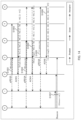
- FIG. 4 is a sequence diagram illustrating an example of a connection process
- FIG. 5 illustrates an example of communication paths between radio nodes
- FIG. 6 is a sequence diagram illustrating an example of a link quality collection process
- FIG. 7 illustrates an example of a link quality matrix
- FIG. 8 is a sequence diagram illustrating an example of the link quality collection process
- FIG. 9 is a sequence diagram illustrating an example of a proxy connection process
- FIG. 10 illustrates an example of communication paths between radio nodes
- FIG. 11 illustrates an example of communication paths between radio nodes
- FIG. 12 is a sequence diagram illustrating an example of the link quality collection process
- FIG. 13 illustrates an example of the link quality matrix
- FIG. 14 is a sequence diagram illustrating an example of a proxy link quality collection process
- FIG. 15 illustrates an example of the link quality matrix and communication paths between radio nodes
- FIG. 16 illustrates an example of the link quality matrix and communication paths between radio nodes
- FIG. 17 is a sequence diagram illustrating an example of a proxy link quality response process
- FIG. 18 illustrates an example of the link quality matrix and communication paths between radio nodes
- FIG. 19 is a sequence diagram illustrating an example of the proxy link quality collection process.
- FIG. 20 illustrates an example of a state transition of radio nodes.
- a radio node that forwards (in other words, relays) a signal (e.g., a message or a packet) in a wireless mesh network is determined based on a layout diagram illustrating a spatial arrangement.
- a layout element e.g., a road
- forwarding the signal is controlled based on layout information such as a geographic distance and a traveling distance.
- the geographic positional relation and distance of the radio node do not match the link quality or propagation environment in the actual radio environment.
- the link quality and propagation environment for each radio node are easily changed. Therefore, in cases where the layout element is associated with a radio node that relays a signal (hereinafter, also referred to as “relay node”), the link quality, for example, at the relay node may be low and the transmission efficiency may thus decrease.
- a node in other words, a communication path
- a communication path dynamically determined based on link qualities between a plurality of radio nodes. For example, in multi-hop communication in a congested radio network with radio nodes, dynamic determination of the communication path based on the link qualities between the radio nodes allows efficient determination of the communication path (or optimization of the communication path). Efficient determination of the communication path can improve the transmission efficiency in the radio network.
- FIG. 1 A illustrates a configuration example of radio network (in other words, radio communication system) 100 according to an exemplary embodiment of the present disclosure.
- FIG. 1 A schematically illustrates the arrangement of radio nodes 0 to 6 constituting radio network 100 .
- communication area 101 indicates the range in which it is possible for radio node 0 to communicate
- communication area 102 indicates the range in which it is possible for radio node 2 to communicate.
- other radio nodes 1 and 3 to 6 similarly have respective communication areas that are ranges in which it is possible for the other radio nodes to communicate (not illustrated).
- the term “communication area” may be replaced with another term such as “coverage” or “service area.”
- communication area 101 of radio node 0 includes radio nodes 1 , 2 , and 3 . Therefore, radio node 0 directly communicates with radio nodes 1 , 2 , and 3 . Meanwhile, in FIG. 1 A , communication area 101 of radio node 0 does not include radio nodes 4 , 5 , and 6 . Therefore, radio node 0 does not directly communicate with radio nodes 4 , 5 , and 6 .
- radio node 2 directly communicates with each of radio nodes 0 , 1 , and 3 to 6 .
- FIG. 1 B illustrates exemplary communication paths 103 between radio nodes 0 to 6 included in radio network 100 according to an exemplary embodiment of the present disclosure.
- Communication paths 103 illustrated in FIG. 1 B illustrate an example of communication paths in radio network 100 that are illustrated by dotted lines connecting between those of radio nodes 0 to 6 which directly communicate with one another.
- radio node 0 is connected by radio links with radio nodes 1 , 2 , and 3 , and thus has communication paths that allow direct communication.
- radio node 0 is not connected by radio links with other radio nodes 4 , 5 , and 6 , and does not have communication paths that allow direct communication.
- radio node 6 is connected with radio nodes 2 , 3 , and 5 by radio links, and thus has communication paths that allow direct communication.
- radio node 6 is not connected by radio links with other radio nodes 0 , 1 , and 4 , and does not have communication paths that allow direct communication.
- the radio nodes collect the qualities of the radio links (hereinafter, also abbreviated as “link qualities”) between the radio nodes in radio network 100 .
- the radio nodes also select a radio node (hereinafter also referred to as “relay node”) that relays information or a signal including the collected link qualities.
- the term “relay” of the information or signal may be replaced with “forwarding” or “multi-hop communication” of the information or signal.
- selecting the radio node for example, the relay node
- selecting the radio node may be regarded as selecting a communication path.
- FIG. 2 is a block diagram illustrating a configuration example of radio node 10 according to an exemplary embodiment of the present disclosure.
- Each of radio nodes 0 to 6 illustrated in FIG. 1 A may have, for example, the configuration of radio node 10 illustrated in FIG. 2 .
- radio node 10 may include, for example, controller 11 , storage 12 , wired communication section 13 , radio communication section 14 , link quality measurer 15 , sensor 16 , and actuator 17 .
- Radio node 10 forwards or collects sensor data (e.g., message) in a wireless sensor network (e.g., radio network 100 ) for wirelessly collecting data sensed, for example, by sensor 16 . Further, radio node 10 may also control actuator 17 based on the collected data.
- sensor data e.g., message
- radio network 100 e.g., radio network 100
- Controller 11 controls, for example, the entire operation or processing of radio node 10 .
- the processing of radio node 10 may be controlled based on a program code or data stored in storage 12 .
- Controller 11 may be composed of, for example, a microprocessor.
- Storage 12 stores, for example, program codes or data to be executed by controller 11 .
- Storage 12 may be composed, for example, of a Random Access Memory (RAM) or a Read Only Memory (ROM).
- RAM Random Access Memory
- ROM Read Only Memory
- Wired communication section 13 is an interface that performs wired communication between radio node 10 and an external apparatus (not illustrated).
- wired communication section 13 is an interface for communicating with another apparatus such as sensor 16 , actuator 17 or the external apparatus (not illustrated).
- Wired communication section 13 may perform wired communication such as serial communication, and communication using Inter-Integrated Circuit (I2C), Serial Peripheral Interface (SPI), General Purpose Input/Output (GPIO), Universal Serial Bus (USB), and Ethernet (registered trademark), for example.
- I2C Inter-Integrated Circuit
- SPI Serial Peripheral Interface
- GPIO General Purpose Input/Output
- USB Universal Serial Bus
- Ethernet registered trademark
- Radio communication section 14 is an interface for performing radio communication between radio nodes 10 .
- Radio communication section 14 may perform radio communication such as low-power communication in the 920-MHz band, and communication using ZigBee (registered trademark), Bluetooth (registered trademark), and WiFi (registered trademark), for example.
- ZigBee registered trademark
- Bluetooth registered trademark
- WiFi registered trademark
- wired communication section 13 and radio communication section 14 mounted may be multiple in number according to a corresponding communication protocol.
- communication between radio node 10 and the external apparatus is not limited to wired communication, but may be radio communication. Therefore, radio node 10 may have a configuration in which wired communication section 13 is omitted.
- Link quality measurer 15 measures the link quality between radio node 10 and another radio node based on a radio signal received by radio communication section 14 , and generates information indicating a measurement result (for example, link quality log information described later).
- the link quality may be, for example, an indicator of the quality of a received signal, such as Receive Signal Strength Indicator (RSSI), Signal to Noise Ratio (SNR), or a bit error rate.
- RSSI Receive Signal Strength Indicator
- SNR Signal to Noise Ratio
- bit error rate bit error rate
- Sensor 16 senses the external environment, for example. Sensing the external environment may include, for example, sensing the temperature, humidity, and illuminance.
- Actuator 17 performs, for example, actuation into the external environment. Actuator 17 may perform actuation such as, for example, turning on a Light Emitting Diode (LED), displaying an image on the display, operating a servomotor, or the like.
- actuation such as, for example, turning on a Light Emitting Diode (LED), displaying an image on the display, operating a servomotor, or the like.
- LED Light Emitting Diode
- radio node 10 may be multiple in number. Alternatively, at least one of sensor 16 and actuator 17 does not have to be mounted on radio node 10 .
- radio node 10 may be connected with an external sensor or actuator via wired communication section 13 (or radio communication section 14 ).
- FIG. 3 is a flowchart illustrating an example of the operation in radio network 100 according to an exemplary embodiment of the present disclosure.
- one of a plurality of radio nodes 10 is configured as a “parent node” and begins the operation illustrated in FIG. 3 .
- the method of determining the parent node from among the plurality of radio nodes 10 may be, for example, a method in which roles (including the role of the parent node) are preconfigured for the plurality of radio nodes 10 , a method in which the parent node (for example, radio node 10 to be started first) is configured based on a starting order among the plurality of radio nodes 10 , or another method.
- radio node 0 is configured as the parent node in radio network 100 illustrated in FIG. 1 A .
- radio node 10 performs a transmission and reception process for transmitting and receiving a beacon (S 101 ).
- the “beacon” is an example of a signal (sent signal) that radio node 10 periodically sends.
- the parent node periodically transmits a signal (e.g., a packet) called “beacon” that includes control information.
- the beacon may include, for example, information indicating that radio node 0 is the parent node.
- the beacon may also include, for example, information indicating the address of the parent node.
- the beacon may also include information on the configuration of radio network 100 , such as a transmission periodicity of the beacon, for example.
- Another radio node 10 different from the parent node receives the beacon to, for example, detect the parent node located near the other radio node 10 and detect that radio network 100 is operating.
- the transmission periodicity of the beacon may be configured according to, for example, the number of radio nodes 10 that can communicate with the parent node (radio node 0 ). For example, the larger the number of radio nodes 10 that can communicate with the parent node, the longer the transmission periodicity may be.
- the parent node (radio node 0 ) and radio node 10 having received the beacon perform a connection process for connection between the parent node (radio node 0 ) and radio node 10 (S 102 ).
- radio node 10 having received the beacon transmits a packet including connection request information (for example, denoted by “REG”) to the parent node.
- Radio node 10 waits a predetermined time until radio node 10 receives a packet including connection permission information (for example, denoted by “RCK”) from the parent node. Meanwhile, after the parent node receives the connection request information and when connection permission can be granted to radio node 10 having transmitted REG, the parent node transmits the packet including the connection permission information (for example, RCK).
- the parent node may, for example, transmit the packet including the connection permission information, or may transmit another transmission packet, such as the beacon, including the connection permission information.
- radio node 10 When radio node 10 receives the connection permission information, radio node 10 is configured as a “child node” for the parent node (radio node 0 ) and enters a connection state (for example, a state in which a radio link is established) with the parent node.
- a connection state for example, a state in which a radio link is established
- the parent node when the parent node (radio node 0 ) does not permit, to connect, radio node 10 having transmitted REG, the parent node (radio node 0 ) may omit transmission of the connection permission information to radio node 10 having transmitted REG, for example, or may transmit, to radio node 10 having transmitted REG, information indicating that the connection is not permitted. Further, based on, for example, a preconfigured connection permission node table or the upper limit of the number of child nodes that can be connected, the parent node may judge whether or not radio node 10 can be granted the connection permission.
- the beacon transmitted by the parent node may be received by radio nodes 1 , 2 , and 3 located within communication area 101 of radio node 0 .
- radio nodes 1 , 2 , and 3 may be configured as child nodes for radio node 0 .
- the parent node and each of the child nodes perform a link quality collection process of transmitting and receiving information on the link quality (for example, also referred to as link quality log information) (S 103 ).
- the parent node transmits a packet including link quality request information (for example, “REQ”) to the child node.
- link quality request information for example, “REQ”
- the child node After receiving the link quality request information, the child node transmits, to the parent node, a packet including the link quality log information (in other words, ACK for the link quality request information “REQ”) retained when the child node receives the link quality request information.
- the link quality log information in other words, ACK for the link quality request information “REQ”
- radio node 10 when each radio node 10 (e.g., child node) receives a signal transmitted by another radio node 10 (including another child node) different from the parent node (radio node 0 ), radio node 10 having received the signal may measure the link quality between radio node 10 (parent node) and the other radio node 10 (child node) based on the received signal and store the link quality log information including a measured value of the link quality.
- the parent node may combine, for example, these pieces of link quality log information to generate a “link quality matrix.”
- a row may represent a transmission node
- a column may represent a reception node
- each element of the matrix may represent the link quality (e.g., RSSI) between the transmission and reception nodes.
- the matrix configuration of the link quality matrix is not limited to this example.
- the parent node may identify the link qualities between a plurality of radio nodes 10 including the child nodes within radio network 100 based on, for example, the link quality matrix.
- the child node and other radio nodes 10 different from both the parent node and the child node perform a proxy connection process (S 104 ).
- radio nodes 10 may include other radio nodes 10 (e.g., radio nodes 4 to 6 in FIG. 1 A ) that do not directly communicate with the parent node (e.g., radio node 0 in FIG. 1 A ) but directly communicate with the child node (e.g., any of radio nodes 1 to 3 in FIG. 1 A ).
- the other radio nodes 10 do not receive the beacon transmitted by the parent node but receive the packet including the link quality log information transmitted by the child node.
- radio nodes 4 , 5 , and 6 are located at least within communication area 102 , and thus receive (in other words, intercept) a packet (including, for example, link quality log information) transmitted by radio node 2 (child node).
- radio nodes 10 can detect the presence of radio network 100 , for example, based on the link quality log information transmitted by the child node.
- radio nodes 10 detect radio network 100
- radio nodes 10 transmit, for example, a packet including proxy connection request information (for example, denoted by “pREG: proxy_REG”) to the child nodes (for example, radio nodes 1 to 3 in FIG. 1 A ).
- proxy connection request information for example, denoted by “pREG: proxy_REG”
- radio nodes 10 may determine, from among the plurality of child nodes, radio node 10 (in other words, a below-described relay node) which performs the proxy connection process, based on the link qualities between radio nodes 10 and the plurality of child nodes with which radio nodes 10 can directly communicate.
- radio node 10 in other words, a below-described relay node
- radio nodes 10 wait a specified time until, for example, a packet including proxy connection permission information (for example, denoted by “pRCK: proxy_RCK”) is received from the child node. Meanwhile, after receiving the proxy connection request information, the child node transmits the packet including the proxy connection permission information when radio nodes 10 having transmitted pREG can be granted the connection permission.
- proxy connection permission information for example, denoted by “pRCK: proxy_RCK”.
- radio nodes 10 When radio nodes 10 (for example, radio nodes 4 to 6 in FIG. 1 A ) receive the proxy connection permission information, radio nodes 10 are configured, for example, as “grandchild nodes” for the parent node. Further, the child nodes are configured as the “relay nodes” for the grandchild nodes as a result of transmission of the proxy connection permission information.
- the proxy connection process of S 104 the child nodes (in other words, the relay nodes) and the grandchild nodes enter the connected state.
- the proxy connection permission information transmitted by the child nodes to the grandchild nodes indicates that the child nodes function as the relay nodes between the parent node and the grandchild nodes.
- the child node may omit transmission of the connection permission information to radio node 10 having transmitted pREG, or may transmit, to radio node 10 having transmitted, for example, pREG, the information indicating that the proxy connection is not permitted. Further, based on, for example, a preconfigured connection permission node table, a child node table of child nodes that can relay and connect the radio nodes, or an upper limit of the number of grandchild nodes that can be connected that is received from the parent node, the child node may judge whether or not the proxy connection permission can be granted to radio node 10 having transmitted pREG.
- the parent node receives (in other words, intercepts) the packet including the proxy connection permission information transmitted by the relay node (in other words, the child node).
- the parent node may detect the presence of a grandchild node and the connection state between the relay node and the grandchild node by receiving the proxy connection permission information.
- the parent node, the relay node (e.g., the child node), and the grandchild node perform a proxy link quality collection process (S 105 ).
- the proxy link quality collection process is, for example, a process in which the relay node (in other words, a proxy of the parent node) collects the link quality log information retained by the grandchild node.
- the relay node transmits a packet including proxy link quality request information (e.g., “pREQ: proxy_REQ”) to the grandchild node.
- proxy link quality request information e.g., “pREQ: proxy_REQ”
- the grandchild node After receiving the proxy link quality request information, the grandchild node transmits, to the relay node, a packet including proxy link quality log information (in other words, ACK for the proxy link quality request information) indicating the link quality retained when the grandchild node receives the proxy link quality request information.
- the relay node may, for example, combine these pieces of proxy link quality log information and generate a proxy link quality matrix.
- the relay node may, for example, partially identify the link qualities between radio nodes 10 within radio network 100 based on the proxy link quality matrix.
- the parent node when the parent node transmits the packet including the link quality request information (REQ) to the relay node, for example, the parent node may transmit, to the relay node, reserved allocation information on a slot in which the relay node performs the proxy link quality collection for the grandchild nodes.
- the relay node may transmit the packet including the proxy link quality request information to the grandchild nodes in the slot indicated in the received reserved allocation information (in other words, the reserved slot).
- the parent node and the relay node performs a proxy link quality response process (S 106 ).
- the relay node when the relay node transmits, to the parent node, the link quality log information indicating the link quality between the relay node and another radio node 10 , the relay node may transmit, to the parent node, the proxy link quality log information including the link quality matrix of link qualities between the relay node and the grandchild nodes retained by the relay node.
- the parent node may, for example, combine the received proxy link quality log information with the retained link quality matrix, and may store the link quality matrix.
- the link quality matrix combined allows the parent node to identify the link qualities between the plurality of radio nodes 10 including the child and grandchild nodes within radio network 100 .
- the parent node may perform a scheduling process such as reassigning the relay node or selecting a communication path between radio nodes 10 , for example, based on the link qualities between the plurality of radio nodes 10 indicated in the link quality matrix.
- a data packet between radio nodes 10 may be included in packets transmitted respectively by the parent node, the child node (or the relay node), and the grandchild node.
- radio node 10 when a communication process has not ended (S 107 : No), radio node 10 returns to the process of S 101 and repeats the above-described processes. On the other hand, when the communication process has ended (S 107 : Yes), radio node 10 ends the process.
- radio nodes 0 to 6 included in radio network 100 illustrated in FIG. 1 A will be described below. Further, a case in which radio node 0 from among radio nodes 0 to 6 is configured as the parent node will be described.
- a communication method between radio nodes 10 is, for example, either broadcast communication or unicast communication.
- the communication method between radio nodes 10 is not limited to these.
- FIG. 4 is a sequence diagram illustrating an example of the connection process.
- Radio node 0 which is the parent node, periodically transmits beacons (S 1011 ).
- radio nodes 1 , 2 , and 3 receive the beacons transmitted by radio node 0 .
- radio nodes 4 , 5 , and 6 located outside communication area 101 do not receive the beacons transmitted by radio node 0 .
- radio nodes 1 , 2 , and 3 having received the beacons transmit, for example, the packet including the connection request information (REG) to the parent node (radio node 0 ) (S 1021 , S 1022 , and S 1023 ).
- Radio nodes 1 , 2 , and 3 may determine transmission timings based on a transmission method such as transmission after carrier sensing or random back-off transmission, for example. This determination of the transmission timings can reduce the probability of collision between packets transmitted respectively by radio nodes 1 , 2 , and 3 .
- radio node 1 first transmits the packet including the connection request information (REG) (S 1021 ), and then radio node 3 transmits the connection request packet (REG) (S 1022 ), and finally, radio node 2 transmits the connection request packet (REG) (S 1023 ).
- radio nodes 1 , 2 , and 3 may, for example, measure (not illustrated) the link qualities between each of radio nodes 0 , 1 , and 2 and the other radio node 10 .
- radio node 0 When radio node 0 permits connection requested by radio nodes 1 , 2 , and 3 , radio node 0 transmits the connection permission information (RCK) to radio nodes 1 , 2 , and 3 (S 1024 ).
- radio node 0 may include the connection permission information for a plurality of radio nodes 10 in a beacon (in other words, a broadcast signal) to be transmitted next.
- the connection permission information may include, for example, a radio node number (e.g., an address) to which the connection permission is granted.
- a radio node number e.g., an address
- the connection permission information includes information (e.g., rck[1, 3, 2]) indicating the order of radio nodes 10 to which the connection is permitted (e.g., the order of 1, 3, and 2).
- radio node 0 may include the connection permission information for each of the plurality of radio nodes 10 in an individual packet (in other words, a unicast signal).
- radio node 0 indicated by the solid line is parent node 0
- radio nodes 1 , 2 , and 3 indicated by the dotted lines are child nodes 1 , 2 , and 3
- parent node 0 is connected with each of child nodes 1 , 2 , and 3 .
- FIG. 6 is a sequence diagram illustrating an example of the link quality collection process.
- the process illustrated in FIG. 6 illustrates, for example, processing after the transmission and reception of beacons illustrated in FIG. 4 (for example, processing of S 1024 illustrated in FIG. 4 .
- parent node 0 After transmitting the connection permission information to child nodes 1 , 2 , and 3 (after the processing of S 1024 illustrated in FIG. 4 ), parent node 0 transmits a packet including link quality request information (REQ) to each of child nodes 1 , 2 , and 3 .
- REQ link quality request information
- parent node 0 transmits the link quality request information to child nodes 1 , 3 , and 2 in the order of child nodes 1 , 3 , and 2 according to the order of radio nodes 10 to which transmissions are performed at “Beacon” in FIG. 4 .
- the order of radio nodes 10 can be configured randomly, for example, and in this case, an earlier order may be given to radio node 10 for which the link quality has not yet been collected.
- parent node 0 transmits the link quality request information (REQ) to child node 1 (S 1031 ).
- child node 1 transmits, to parent node 0 , the link quality response information (ACK) including the link quality log information (for example, “rlog”) retained when receiving the link quality request information (S 1032 ).
- Parent node 0 receives the link quality log information transmitted by child node 1 and stores it in a link quality matrix.
- child node 1 may receive (or intercept) the packets from parent node 0 (e.g., beacons received in S 1011 and S 1024 illustrated in FIG. 4 ) and the packets transmitted by the other child nodes 2 and 3 (e.g., packets transmitted in S 1022 and S 1023 illustrated in FIG. 4 ), and may measure the link qualities (e.g., RSSIs) between other radio nodes 10 and child node 1 based on the received signals.
- parent node 0 e.g., beacons received in S 1011 and S 1024 illustrated in FIG. 4
- the packets transmitted by the other child nodes 2 and 3 e.g., packets transmitted in S 1022 and S 1023 illustrated in FIG. 4
- the link qualities e.g., RSSIs
- the link quality log information may be represented by a list including, for example, a set [sa, rssi] of a transmitter address (e.g., a radio node number) “sa” and an RSSI “rssi”.
- the link quality log information transmitted by child node 1 is, for example, [[3, ⁇ 90], [2, ⁇ 87], [0, ⁇ 87]].
- the link quality log information e.g., RSSI
- link quality e.g., RSSI
- radio nodes 10 located in a communication area of each radio node 10 in radio network 100 illustrated in FIG. 1 A may receive (in other words, intercept) a packet transmitted by each radio node 10 and update the link quality log information.
- parent node 0 transmits the link quality request information (REQ) to child node 3 (S 1033 ).
- child node 3 After receiving the link quality request information, child node 3 transmits the link quality response information (ACK) including the link quality log information to parent node 0 (S 1034 ).
- REQ link quality request information
- ACK link quality response information
- parent node 0 transmits the link quality request information (REQ) to child node 2 (S 1035 ).
- child node 2 After receiving the link quality request information, child node 2 transmits the link quality response information (ACK) including the link quality log information to parent node 0 (S 1036 ).
- REQ link quality request information
- ACK link quality response information
- parent node 0 transmits the beacons according to, for example, a beacon periodicity (S 1012 ).
- parent node 0 retains the link quality matrix including the link qualities (e.g., RSSIs) for communication paths 103 a illustrated in FIG. 7 .
- the link quality log information generated based on the packets transmitted by child nodes 1 , 2 , and 3 to parent node 0 is [[1, ⁇ 87], [2, ⁇ 88], [3, ⁇ 88]].
- FIG. 8 exemplarily illustrates the link quality collection process (processes of S 1031 a to S 1036 a ) for child nodes 1 to 3 after the transmission of the beacons (after the process of S 1012 ) illustrated in FIG. 6 .
- parent node 0 identifies (or updates) the link qualities between the radio nodes in the radio network by repeating such a link quality collection process (see, for example, FIGS. 8 , 12 , and 14 ).
- Proxy Connection Process (Process of S 104 Illustrated in FIG. 3 )
- FIG. 9 is a sequence diagram illustrating an example of the proxy connection process.
- the process illustrated in FIG. 9 illustrates processing after the link quality collection process illustrated in FIG. 8 (for example, the process of S 1036 a illustrated in FIG. 8 ).
- Radio nodes 4 , 5 , and 6 do not receive beacons transmitted by parent node 0 because they are outside communication area 101 of parent node 0 . Meanwhile, radio nodes 4 , 5 and 6 receive (in other words, intercept) signals transmitted by child nodes 1 , 2 and 3 to parent node 0 , such as those transmitted, for example, at S 1032 , S 1034 , or S 1036 illustrated in FIG. 6 or S 1032 a , S 1034 a , or S 1036 a illustrated in FIG. 8 .
- radio nodes 4 , 5 , and 6 may measure the link qualities between the transmitter child node and radio nodes 4 , 5 , and 6 based on the received signals, for example, and determine the child node to be configured as the relay node based on measured values of the link qualities.
- radio nodes 4 , 5 , and 6 transmit a packet including the proxy connection request information (pREG) to the child node configured as the relay node.
- radio nodes 4 , 5 , and 6 may transmit the proxy connection request information to a child node that is a transmitter of one of the received packets which has a higher reception power (e.g., a packet having the highest reception power).
- radio node 5 transmits the proxy connection request information (pREG 5 ) to child node 2 that is the transmitter of one of the intercepted packets which has the highest reception power (S 1041 ).
- child node 2 After receiving the proxy connection request information from radio node 5 , child node 2 transmits the proxy connection permission information (pRCK 5 ) to radio node 5 when it is judged that the proxy connection can be permitted (S 1042 ).
- radio node 5 determines that the connection with child node 2 is permitted and configured as grandchild node 5 for parent node 0 .
- radio node 5 may transmit the retained link quality log information (for example, rlog[[1, ⁇ 90], [3, ⁇ 85], [2, ⁇ 81], [1, ⁇ 90], [3, ⁇ 85], [2, ⁇ 81]]) to child node 2 when transmitting the proxy connection request information (when performing the process of S 1041 ).
- Child node 2 may add, to the link quality log information retained by child node 2 , the link quality log information transmitted by radio node 5 .
- radio nodes 10 capable of directly communicating with radio node 5 receive (in other words, intercept) the proxy connection request information (packet transmitted in S 1041 ) transmitted by radio node 5 .
- child nodes 1 and 3 may measure the link qualities between child nodes 1 and 3 and radio node 5 and generate the link quality log information based on the packet transmitted by radio node 5 .
- Radio nodes 4 and 6 may similarly generate the link quality log information.
- the proxy connection permission information (packet transmitted in S 1042 ) transmitted by child node 2 is also received (in other words, intercepted) by parent node 0 and child nodes 1 and 3 . Therefore, for example, parent node 0 can detect the connection between child node 2 and grandchild node 5 (in other words, that child node 2 is configured as the relay node for grandchild node 5 ). Note that, parent node 0 may notify child nodes 1 , 2 , and 3 of the detection of grandchild node 5 , for example, by using a beacon including the connection permission information (RCK) (the process of S 1047 described below).
- RCK connection permission information
- radio node 4 transmits the proxy connection request information (pREG 4 ) to child node 2 that is the transmitter of one of the intercepted packets which has the highest reception power (S 1043 ), and child node 2 transmits the proxy connection permission information (pRCK 4 ) to radio node 4 (S 1044 ).
- radio node 4 determines that radio node 4 is permitted to connect with child node 2 (for example, the relay node) and is configured as grandchild node 4 for parent node 0 .
- radio node 6 transmits the proxy connection request information (pREG 6 ) to child node 3 that is the transmitter of one of the intercepted packets which has the highest reception power (S 1045 ), and child node 3 transmits the proxy connection permission information (pRCK 6 ) to radio node 6 (S 1046 ).
- radio node 6 determines that radio node 6 is permitted to connect with child node 3 (for example, the relay node) and is configured as grandchild node 6 for parent node 0 .
- child node 2 is connected with grandchild nodes 4 and 5
- child node 3 is connected with grandchild node 6 , for example, as illustrated in FIG. 10 .
- radio nodes 10 indicated by one-dot chain lines are grandchild nodes 4 , 5 , and 6 .
- Grandchild nodes 4 and 5 are connected with child node 2
- grandchild node 6 is connected with child node 3 .
- parent node 0 transmits the beacons including the connection permission information (RCK) on grandchild nodes 5 , 4 , and 6 , for example, in accordance with a beacon periodicity (S 1047 ).
- the connection relationship with the grandchild nodes is notified within radio network 100 by transmission of the connection permission information.
- FIG. 11 illustrates an example of connection relation between radio nodes 10 (parent node 0 , child nodes 1 to 3 , and grandchild nodes 4 to 6 ) after the process of S 1047 illustrated in FIG. 9 .
- Proxy Link Quality Collection Process (Process of S 105 Illustrated in FIG. 3 )
- FIG. 12 exemplarily illustrates the link quality collection process (processes of S 1031 b to S 1036 b ) for child nodes 1 to 3 after the transmission of the beacons (after the process of S 1047 ) illustrated in FIG. 9 .
- the link quality collection process illustrated in FIG. 12 is, for example, the same as the link quality collection process illustrated in FIG. 6 or FIG. 8 (for example, the processes of S 1031 to S 1036 or S 1031 a to S 1036 a ).
- the link quality request information (REQ 2 transmitted in S 1035 b ) transmitted by parent node 0 to child node 2 that is the relay node for grandchild nodes 4 and 5 may include information (for example, rsv14) indicating a time (for example, a reservation time) at which child node 2 performs the proxy link quality collection.
- the link quality request information (REQ 3 transmitted in S 1033 b ) transmitted by parent node 0 to child node 3 that is the relay node for grandchild node 6 may include information (for example, rsv19) indicating a time (for example, a reservation time) at which child node 3 performs the proxy link quality collection.
- parent node 0 can grasp the link quality log information (e.g., rlog) relevant to the link qualities of grandchild nodes 4 to 6 measured based on the packets received by the child nodes. For example, at the end of the process illustrated in FIG. 12 , parent node 0 retains the link quality matrix including the link qualities (e.g., RSSIs) of communication paths 103 b illustrated in FIG. 13 . For example, by the link quality collection process illustrated in FIG. 12 , parent node 0 can identify the link qualities transmitted by grandchild nodes 4 to 6 and received by child nodes 1 , 2 , and 3 , as illustrated in FIG. 13 (e.g., a portion boxed by a dotted line).
- link quality log information e.g., rlog
- parent node 0 retains the link quality matrix including the link qualities (e.g., RSSIs) of communication paths 103 b illustrated in FIG. 13 .
- parent node 0 can identify the link qualities transmitted by grandchild nodes
- FIG. 14 is a sequence diagram illustrating an example of the proxy link quality collection process.
- the processes illustrated in FIG. 14 illustrate, for example, processes after the process of S 1036 b illustrated in FIG. 12 .
- a time after the time at which the process of S 1036 b is performed is allocated as the reservation time of proxy link quality collection for child node 2
- a time after the time at which the process of S 1054 is performed is allocated as the reservation time of proxy link quality collection for child node 3 .
- child node 2 transmits the packet including the proxy link quality request information (pREQ 5 and pREQ 4 ) to grandchild nodes 5 and 4 .
- child node 2 transmits the proxy link quality request information (pREQ) to grandchild nodes 5 and 4 in the order of grandchild nodes 5 and 4 , which is a randomly configured transmission order (S 1051 and S 1053 ).
- grandchild node 5 After receiving the proxy link quality request information (pREQ 5 ), grandchild node 5 transmits the link quality response information (ACK 5 ) including the link quality log information retained by grandchild node 5 to child node 2 (S 1052 ). Likewise, for example, after receiving the proxy link quality request information (pREQ 4 ), grandchild node 4 transmits the link quality response information (ACK 4 ) including the link quality log information retained by grandchild node 4 to child node 2 (S 1054 ).
- child node 2 retains the link quality matrix including the link qualities (e.g., RSSIs) relevant to grandchild nodes 4 and 5 in communication paths 103 c illustrated in FIG. 15 .
- the link qualities e.g., RSSIs
- child node 3 transmits the proxy link quality request information (pREQ 6 ) to grandchild node 6 (S 1055 ).
- grandchild node 6 After receiving the proxy link quality request information, grandchild node 6 transmits the link quality response information (ACK 6 ) including the link quality log information retained by grandchild node 6 to child node 3 (S 1056 ).
- child node 3 retains the link quality matrix including the link qualities (e.g., RSSIs) relevant to grandchild node 6 in communication paths 103 d illustrated in FIG. 16 .
- the link qualities e.g., RSSIs
- parent node 0 transmits beacons according to a beacon periodicity (S 1057 ).
- Proxy Link Quality Response Process (Process of S 106 Illustrated in FIG. 3 )
- FIG. 17 is a sequence diagram illustrating an example of the proxy link quality response process.
- the processes illustrated in FIG. 17 illustrate, for example, processes after the process of S 1057 illustrated in FIG. 14 .
- the processing of S 1031 c to S 1036 c illustrated in FIG. 17 is, for example, the same as the link quality collection process illustrated in FIG. 3 (for example, see FIGS. 6 , 8 , and 12 ).
- child node 3 is the relay node for grandchild node 6 . Therefore, in FIG. 17 , in response to the link quality request (REQ 3 ; processing of S 1033 c ) of parent node 0 , child node 3 transmits, to parent node 0 , the response information (ACK 3 ) including the proxy link quality log information (e.g., plog: ploxy log) indicating the link quality log information (e.g., see FIG. 16 ) relevant to grandchild node 6 that is retained by child node 3 (S 1034 c ).
- the proxy link quality log information e.g., plog: ploxy log
- Proxy link quality log information “plog” is, for example, information obtained by adding destination (or addressee) address “da” to link quality log information “rlog” received by the child node, and may be represented by a list including a set [da, sa, rssi] of destination (or addressee) address “da,” transmitter address “sa,” and RSSI “rssi.
- child node 2 is the relay node for grandchild nodes 4 and 5 . Therefore, in FIG. 17 , in response to the link quality request (REQ; processing of S 1035 c ) of parent node 0 , child node 2 transmits, to parent node 0 , the response information (ACK) including the proxy link quality log information (e.g., plog) indicating the link quality log information (e.g., see FIG. 15 ) relevant to grandchild nodes 4 and 5 that is retained by child node 2 (S 1034 c ).
- the proxy link quality log information e.g., plog
- parent node 0 When receiving the proxy link quality log information, parent node 0 combines, for example, the proxy link quality log information with the retained link quality matrix, and stores the resultant link quality matrix.
- child node 3 may transmit not only the proxy link quality log information (plog) but also the link quality log information (rlog) relevant to child node 3 to parent node 0 , for example, as illustrated in FIG. 17 .
- child node 2 may transmit not only the proxy link quality log information (plog) but also the link quality log information (rlog) relevant to child node 2 to parent node 0 , for example, as illustrated in FIG. 17 .
- child node 1 is not configured as the relay node of any of radio nodes 10 , and child node 1 may transmit, for example, the link quality log information (rlog) relevant to child node 1 to parent node 0 (S 1032 c ).
- parent node 0 retains the link quality matrix including the link qualities (e.g., RSSIs) of communication paths 103 e illustrated in FIG. 18 .
- link qualities e.g., RSSIs
- parent node 0 can identify the link qualities between grandchild nodes 4 , 5 , and 6 as illustrated in FIG. 18 (e.g., a portion boxed by a dotted line).
- FIG. 19 is a sequence diagram illustrating an example of the proxy link quality collection process.
- the processes illustrated in FIG. 19 illustrate, for example, processes after the process of S 1036 c illustrated in FIG. 17 .
- the processing of S 1051 a to S 1057 a illustrated in FIG. 19 is the same as the proxy link quality collection process illustrated in FIG. 14 (for example, the processing of S 1051 to S 1057 ).
- parent node 0 identifies (or updates) the link qualities between radio nodes 10 in the radio network by repeating the proxy link quality collection process and the proxy link quality response process (see, for example, FIGS. 14 , 17 , and 19 ).
- Radio node 10 may update the link quality log information on the link qualities between radio nodes 10 in radio network 100 by repeating the operation described above. Further, radio node 10 may reassign the relay node or select paths between radio nodes 10 based on the link quality log information.
- FIG. 20 illustrates an example of state transition of radio nodes 10 .
- the state transition illustrated in FIG. 20 may be achieved by, for example, a program stored in storage 12 of radio node 10 (see, e.g., FIG. 2 ) and executed by controller 11 .
- state transitions relevant to S 1 to S 5 represent state transitions of the parent node
- state transitions relevant to S 6 to S 14 represent state transitions of the child node
- state transitions relevant to S 15 to S 19 represent state transitions of the grandchild node.
- radio node 10 may have a transition (not illustrated) for returning to reset state S 1 in each state in FIG. 20 that is performed when detecting an abnormality or time-out.
- radio node 10 determines whether or not radio node 10 is configured as the parent node. Radio node 10 transitions to beacon transmission state S 2 (T 1 a ) when configured as the parent node, and transitions to reception awaited state S 6 (T 1 b ) when not configured as the parent node.
- radio node 10 transmits a beacon packet.
- the beacon packet may include, for example, at least one of a type indicating a beacon (in other words, a packet type), an address of radio node 10 , a destination address (e.g., a broadcast address), a beacon periodicity, reserved allocation slot information, address information on a connection permission node, and inter-node path information.
- Radio node 10 transitions to REG awaited state S 3 (T 2 a ) when there is no connected child node, and transitions to REQ transmission state S 4 (T 2 b ) when there is a connected child node.
- radio node 10 awaits to receive connection request information (REG) from another radio node 10 .
- radio node 10 adds, for example, the transmitter address of the transmitter of the connection request packet to the address information on the connection permission node.
- radio node 10 receives (in other words, intercepts) proxy connection permission information (pRCK) transmitted by a child node for radio node 10 and connection is possible, radio node 10 adds, for example, the destination address of the proxy connection permission information to the address information on the connection permission node.
- pRCK proxy connection permission information
- radio node 10 transitions to beacon transmission state S 2 at a beacon transmission timing in accordance with the beacon periodicity (T 3 a ), and stays in REG awaited state S 3 except at the beacon transmission timing (T 3 b ).
- radio node 10 transmits link quality request information (REQ) to a child node connected with radio node 10 .
- Radio node 10 may sequentially transmit the link quality request information (REQ) to child nodes. Further, when the child node is a relay node for a grandchild node, radio node 10 may notify the child node of information (for example, reserved allocation slot information) indicating the timing at which the proxy link quality request information (pREQ) is transmitted.
- Radio node 10 transitions to ACK awaited state S 5 (T 4 ).
- radio node 10 awaits to receive the link quality response information (ACK) transmitted by the child node in response to the link quality request information (REQ) transmitted in REQ transmission state S 4 .
- radio node 10 transitions to REQ transmission state S 4 (T 5 b ) when there is another child node, and transitions to REG awaited state S 3 (T 5 a ) when the link quality request information (REQ) has been transmitted to all the child nodes.
- radio node 10 stays in ACK awaited state S 5 for a configured time (in other words, an allowable time) related to awaiting the link quality response information (T 5 c ).
- Radio node 10 combines the link quality log information (in other words, the link quality for the child node) and the proxy link quality log information (in other words, the link quality for the grandchild node) included in the link quality response information from the child node, and updates the link quality matrix.
- radio node 10 In reception awaited state S 6 , radio node 10 awaits to receive a signal (in other words, a packet) transmitted by another radio node 10 . In reception awaited state S 6 , radio node 10 is not in a connection state of being connected with the parent node. For example, when radio node 10 receives a beacon and judges to be connected with another radio node 10 (in other words, the parent node) being the transmitter of the beacon, radio node 10 transitions to REG transmission waiting state S 7 (T 6 a ).
- radio node 10 when radio node 10 receives (in other words, intercepts) the link quality response information (ACK) and judges to be connected with another radio node 10 (in other words, a child node) being the transmitter of the link quality response information, radio node 10 transitions to pREG transmission waiting state S 15 (T 6 b ). Further, when judging not to be connected with another radio node 10 corresponding to the parent node or the child node, radio node 10 stays, for example, in reception awaited state S 6 (T 6 c ).
- radio node 10 waits until the connection request information (REG) can be transmitted. In other words, radio node 10 stays in REG transmission waiting state S 7 (T 7 b ) until the connection request information (REG) can be transmitted. For example, radio node 10 may wait to perform transmission until completion of transmission of another radio node 10 sensed by carrier sensing or until elapse of a randomly configured back-off time. This waiting of transmission can suppress packet collisions between radio nodes 10 . For example, radio node 10 transitions to REG transmission state S 8 (T 7 a ) at a timing at which the connection request information (REG) can be transmitted.
- radio node 10 transmits the connection request information (REG) to the parent node that transmitted the beacon, and transitions to RCK awaited state S 9 (T 8 ).
- REG connection request information
- radio node 10 awaits to receive the connection permission information (RCK) from the parent node. For example, radio node 10 stays in RCK awaited state S 9 until radio node 10 receives a beacon including the connection permission information (RCK) from the parent node (T 9 b ). When the connection permission information (RCK) included in the beacon received from the parent node includes the address of radio node 10 , radio node 10 judges that the connection with the parent node has been established, and transitions to Parent awaited state S 10 (T 9 a ). In other words, radio node 10 determines to have been configured as the child node for the parent node.
- RCK connection permission information
- radio node 10 In Parent awaited state S 10 , radio node 10 (in other words, the child node) awaits to receive a signal (e.g., packet) from the parent node, for example.
- a signal e.g., packet
- radio node 10 continues the connection state of being connected with the parent node when radio node 10 receives a beacon from the parent node. Radio node 10 stays in Parent awaited state S 10 while radio node 10 is configured as the child node (T 10 c ).
- radio node 10 may update the control information on radio network 100 , such as, for example, the beacon periodicity and path information on paths between radio nodes 10 . Further, when receiving the link quality request information (REQ) from the parent node, radio node 10 transitions to ACK transmission state S 11 (T 10 a ).
- REQ link quality request information
- radio node 10 when radio node 10 receives the proxy connection request information (pREG) from another radio node 10 and can be connected with the other radio node 10 , radio node 10 transitions to pRCK transmission state S 14 (T 10 b ). Further, when receiving (in other words, intercepting) a signal from another child node (e.g., link quality response information (ACK)), radio node 10 may measure the link quality (e.g., RSSI) based on the signal to update the retained link quality log.
- a signal from another child node e.g., link quality response information (ACK)
- ACK link quality response information
- radio node 10 transmits the link quality response information (ACK) to the parent node.
- radio node 10 may transmit the proxy link quality log information to the parent node, for example, when radio node 10 retains the proxy link quality log information on a grandchild node connected with radio node 10 .
- radio node 10 transitions to pREQ transmission state S 12 (T 11 a ) at the timing of the reserved slot.
- Radio node 10 transitions to Parent awaited state S 10 during a time other than the timing of the reserved slot (T 11 b ).
- radio node 10 transmits the proxy link quality request information (pREQ) to the grandchild node connected with radio node 10 and transitions to ACK awaited state S 13 (T 12 ).
- pREQ proxy link quality request information
- radio node 10 awaits to receive the link quality response information (ACK) transmitted by the grandchild node in response to the proxy link quality request information (pREQ) transmitted in pREQ transmission state S 12 .
- radio node 10 stays in ACK awaited state S 13 for a configured time (in other words, an allowable time) related to awaiting the link quality response information (T 13 c ).
- ACK awaited state S 13 radio node 10 receives the link quality response information (ACK) from the grandchild node.
- radio node 10 transitions to pREQ transmission state S 12 (T 13 b ) and receives the link quality response information (ACK) from the grandchild nodes.
- radio node 10 transitions to Parent awaited state S 10 (T 13 a ).
- radio node 10 combines pieces of the proxy link quality log information (in other words, link qualities for the child nodes) included in the link quality response information from the grandchild nodes and updates the proxy link quality matrix.
- radio node 10 transmits the proxy connection permission information (pRCK) to radio node 10 having transmitted the proxy connection request, and transitions to Parent awaited state S 10 (T 14 ).
- pRCK proxy connection permission information
- radio node 10 waits until the proxy connection request information (pREG) can be transmitted. In other words, radio node 10 stays in pREG transmission waiting state S 15 until the proxy connection request information (pREG) can be transmitted (T 15 b ). For example, radio node 10 may wait to perform transmission until completion of transmission of another radio node 10 sensed by carrier sensing or until elapse of a randomly configured back-off time. This waiting of transmission can suppress packet collisions between radio nodes 10 . For example, radio node 10 transitions to pREG transmission state S 16 (T 15 a ) at a timing at which the proxy connection request information (pREG) can be transmitted.
- radio node 10 transmits the proxy connection request information (pREG) to the child node and transitions to pRCK awaited state S 17 (T 16 ).
- pREG proxy connection request information
- radio node 10 awaits to receive the proxy connection permission information (pRCK) from the child node. For example, radio node 10 stays in pRCK awaited state S 17 until radio node 10 receives a packet including the proxy connection permission information (pRCK) from the child node (T 17 b ).
- radio node 10 judges that the connection with the child node has been completed, and transitions to Proxy awaited state S 18 (T 17 a ). In other words, radio node 10 determines to have been configured as the grandchild node for the parent node.
- radio node 10 (in other words, the grandchild node) awaits to receive a signal from the child node, for example.
- radio node 10 continues the connection state of being connected with the child node when radio node 10 receives a signal from the child node.
- Radio node 10 stays in Proxy awaited state S 18 while radio node 10 is configured as the grandchild node (T 18 b ).
- radio node 10 may update the control information on radio network 100 , such as, for example, the beacon periodicity and path information on paths between radio nodes 10 . Further, when receiving the proxy link quality request information (pREQ) from the child node, radio node 10 transitions to ACK transmission state S 19 (T 18 a ).
- pREQ proxy link quality request information
- radio node 10 when receiving the proxy connection request information (pREG) from another radio node 10 , radio node 10 may serve as the relay node to perform an operation related to proxy connection with the other radio node 10 when being capable of connecting with the other radio node 10 .
- radio node 10 transmits the link quality response information (ACK) to the child node and transitions to Proxy awaited state S 18 (T 19 ).
- ACK link quality response information
- radio node 10 transmits the proxy connection request to the child node upon receipt of a signal (for example, including the link quality response information) transmitted by the child node to the parent node in response to a request of the parent node (for example, including the link quality request information), and receives connection permission from the child node, thereby enabling communication with the parent node via the child node.
- radio node 10 that is the parent node detects the grandchild node by receiving the connection permission transmitted by the child node to the grandchild node in response to the proxy connection request.
- the grandchild node upon receipt of, for example, a signal transmitted by each of a plurality of child nodes to the parent node, the grandchild node can dynamically determine a child node to be configured as the relay node. Therefore, according to the present embodiment, it is possible to efficiently determine radio node 10 (in other words, the communication path) involved in multi-hop transmission between a plurality of radio nodes 10 .
- the grandchild node begins the proxy connection request process by intercepting a signal addressed to another radio node (for example, the parent node) and connects with the child node. Further, the parent node detects a grandchild node (in other words, connection between a child node and the grandchild node) by intercepting a signal addressed to another radio node (for example, addressed to the grandchild node). Therefore, according to the present embodiment, it is possible to suppress an increase in control signals related to the proxy connection request process.
- a grandchild node in other words, connection between a child node and the grandchild node
- the grandchild node measures the link quality between the child node and the grandchild node based on, for example, the reception level (e.g., RSSI) of a signal transmitted by the child node to the parent node, and determines, based on the measured link quality, a radio node (e.g., a relay node) to which the proxy connection request is to be transmitted.
- a radio node e.g., a relay node
- the grandchild node may determine, from among a plurality of child nodes, one child node to which the proxy connection request is to be transmitted.
- the communication path (in other words, the relay node) between those radio nodes 10 which do not directly communicate with each other is determined based on the link qualities between radio nodes 10 .
- a plurality of radio nodes 10 in radio network 100 can efficiently determine the communication path (for example, the relay node) according to a change in the link quality or the propagation environment in the actual radio environment. Efficient determination of the communication path can improve the transmission efficiency in radio network 100 .
- one exemplary embodiment of the present disclosure has been described in relation to the relay (or forwarding) of a message between three radio nodes 10 of the parent node, the child node, and the grandchild node, but the present disclosure is not limited to this.
- an exemplary embodiment of the present disclosure may be applied to a relay (or forwarding) of a message between four or more radio nodes 10 .
- the grandchild node may further be configured as a relay node for collecting the link quality of the other radio nodes by proxy.
- FIG. 1 A a case in which a certain radio node 10 (radio node 0 in FIG. 1 A as an example) and other radio nodes 4 to 6 located outside communication area 101 of radio node 0 do not directly communicate with each other.
- the environment in which direct communication is not performed is not limited to this case.
- a case may be probable in which any of radio nodes 1 to 3 located within communication area 101 of radio node 0 does not directly communicate with radio node 0 .
- a case may be probable in which existence of a blocking object between radio node 0 and any of radio nodes 1 to 3 causes the radio nodes not to communicate with each other.
- Each functional block used in the description of each embodiment described above is typically realized by an LSI, which is an integrated circuit.
- the integrated circuit controls each functional block used in the description of the above embodiments and may include an input and an output.
- the LSI may be individually formed as chips, or one chip may be formed so as to include a part or all of the functional blocks.
- the LSI herein may be referred to as an IC, a system LSI, a super LSI, or an ultra LSI depending on a difference in the degree of integration.
- the technique of implementing an integrated circuit is not limited to the LSI and may be realized by using a dedicated circuit, a general-purpose processor, or a special-purpose processor.
- a Field Programmable Gate Array FPGA
- FPGA Field Programmable Gate Array
- the present disclosure can be realized by any kind of apparatus, device or system having a function of communication, which is referred to as a communication apparatus.
- the communication apparatus may comprise a transceiver and processing/control circuitry.
- the transceiver may comprise and/or function as a receiver and a transmitter.
- the transceiver, as the transmitter and receiver, may include an RF (radio frequency) module and one or more antennas.
- the RF module may include an amplifier, an RF modulator/demodulator, or the like.
- Such a communication apparatus include a phone (e.g., cellular (cell) phone, smart phone), a tablet, a personal computer (PC) (e.g., laptop, desktop, netbook), a camera (e.g., digital still/video camera), a digital player (digital audio/video player), a wearable device (e.g., wearable camera, smart watch, tracking device), a game console, a digital book reader, a telehealth/telemedicine (remote health and medicine) device, and a vehicle providing communication functionality (e.g., automotive, airplane, ship), and various combinations thereof.
- a phone e.g., cellular (cell) phone, smart phone
- a tablet e.g., a personal computer (PC) (e.g., laptop, desktop, netbook)
- a camera e.g., digital still/video camera
- a digital player digital audio/video player
- a wearable device e.g., wearable camera, smart watch, tracking device
- the communication apparatus is not limited to be portable or movable, and may also include any kind of apparatus, device or system being non-portable or stationary, such as a smart home device (e.g., an appliance, lighting, smart meter, control panel), a vending machine, and any other “things” in a network of an “Internet of Things (IoT)”.
- a smart home device e.g., an appliance, lighting, smart meter, control panel
- vending machine e.g., a vending machine, and any other “things” in a network of an “Internet of Things (IoT)”.
- IoT Internet of Things
- the communication may include exchanging data through, for example, a cellular system, a wireless LAN system, a satellite system, etc., and various combinations thereof.
- the communication apparatus may comprise a device such as a controller or a sensor which is coupled to a communication device performing a function of communication described in the present disclosure.
- the communication apparatus may comprise a controller or a sensor that generates control signals or data signals which are used by a communication device performing a communication function of the communication apparatus.
- the communication apparatus also may include an infrastructure facility, such as a base station, an access point, and any other apparatus, device or system that communicates with or controls apparatuses such as those in the above non-limiting examples.
- an infrastructure facility such as a base station, an access point, and any other apparatus, device or system that communicates with or controls apparatuses such as those in the above non-limiting examples.
- section used for the components may be replaced with another expression such as “circuit (circuitry),” “device,” “unit,” or “module.”
- a radio communication system includes: a first radio node; one or more second radio nodes that are connected with the first radio node and that transmit a signal to the first radio node; and a third radio node that transmits a connection request to the one or more second radio nodes when receiving the signal addressed to the first radio node, in which, when the one or more second radio nodes receives the connection request, the one or more second radio nodes transmit connection permission to the third radio node, the connection permission indicating that the one or more second radio nodes function as a relay node between the first radio node and the third radio node.
- the signal transmitted by the one or more second radio nodes to the first radio node includes information on received quality measured by the one or more second radio nodes.
- the one or more second radio nodes transmit, to the third radio node, a request for information on received quality measured by the third radio node, the third radio node transmits the information on the received quality measured by the third radio node to the one or more second radio nodes in response to the request for the information, and the one or more second radio nodes transmit, to the first radio node, a signal including the information on the received quality measured by the third radio node.
- the one or more second radio nodes include a plurality of second radio nodes, and, based on a level at which the third radio node receives the signal transmitted by each of the plurality of second radio nodes to the first radio node, the third radio node determines, from among the plurality of second radio nodes, one second radio node to which the connection request is transmitted.
- the third radio node is located outside a range in which it is possible for the first radio node to communicate and is located within a range in which it is possible for the one or more second radio nodes to communicate.
- a radio communication apparatus includes: reception circuitry, which, in operation, receives a signal transmitted to a first radio node by a second radio node; and transmission circuitry, which, in operation, transmits a connection request to the second radio node when the reception circuitry receives the signal transmitted to the first radio node, in which the reception circuitry receives connection permission from the second radio node in response to the connection request, the connection permission indicating that the second radio node functions as a relay node between the radio communication apparatus and the first radio node.
- a radio communication control method is a radio communication control method for a radio communication system including a first radio node, a second radio node, and a third radio node, the radio communication control method comprising: transmitting, by the second radio node, a signal to the first radio node in response to a request of the first radio node connected with the second radio node; transmitting, by the third radio node, a connection request to the second radio node when the third radio node receives the signal addressed to the first radio node;
- connection permission to the third radio node when the second radio node receives the connection request, the connection permission indicating that the second radio node functions as a relay node between the first radio node and the third radio node.
- One aspect of the present disclosure is applicable to radio communication systems.
Landscapes
- Engineering & Computer Science (AREA)
- Computer Networks & Wireless Communication (AREA)
- Signal Processing (AREA)
- Mobile Radio Communication Systems (AREA)
Abstract
Description
- Japanese Unexamined Patent Application Publication (Translation of PCT Application) No. 2016-506198
-
- 10 Radio node
- 11 Controller
- 12 Storage
- 13 Wired communication section
- 14 Radio communication section
- 15 Link quality measurer
- 16 Sensor
- 17 Actuator
Claims (4)
Applications Claiming Priority (3)
| Application Number | Priority Date | Filing Date | Title |
|---|---|---|---|
| JP2019-144493 | 2019-08-06 | ||
| JP2019144493A JP7266182B2 (en) | 2019-08-06 | 2019-08-06 | Wireless communication system, wireless communication device and wireless communication control method |
| PCT/JP2020/027863 WO2021024760A1 (en) | 2019-08-06 | 2020-07-17 | Wireless communication system, wireless communication device, and wireless communication control method |
Related Parent Applications (1)
| Application Number | Title | Priority Date | Filing Date |
|---|---|---|---|
| PCT/JP2020/027863 Continuation WO2021024760A1 (en) | 2019-08-06 | 2020-07-17 | Wireless communication system, wireless communication device, and wireless communication control method |
Publications (2)
| Publication Number | Publication Date |
|---|---|
| US20220159546A1 US20220159546A1 (en) | 2022-05-19 |
| US12309683B2 true US12309683B2 (en) | 2025-05-20 |
Family
ID=74503790
Family Applications (1)
| Application Number | Title | Priority Date | Filing Date |
|---|---|---|---|
| US17/590,671 Active 2041-07-25 US12309683B2 (en) | 2019-08-06 | 2022-02-01 | Wireless communication system, wireless communication device, and wireless communication control method |
Country Status (3)
| Country | Link |
|---|---|
| US (1) | US12309683B2 (en) |
| JP (1) | JP7266182B2 (en) |
| WO (1) | WO2021024760A1 (en) |
Families Citing this family (3)
| Publication number | Priority date | Publication date | Assignee | Title |
|---|---|---|---|---|
| JP7634183B2 (en) * | 2022-01-18 | 2025-02-21 | パナソニックIpマネジメント株式会社 | Equipment system, information terminal and control method |
| JP7693592B2 (en) * | 2022-03-14 | 2025-06-17 | 株式会社東芝 | Network system, root node, edge node and program |
| JP7364816B1 (en) * | 2023-03-30 | 2023-10-18 | ソフトバンク株式会社 | Systems, information processing devices, programs, and management methods |
Citations (6)
| Publication number | Priority date | Publication date | Assignee | Title |
|---|---|---|---|---|
| US20150264628A1 (en) | 2014-03-14 | 2015-09-17 | Fujitsu Limited | Method for digital communication, radio communication system, and radio communication apparatus |
| JP2016506198A (en) | 2013-01-08 | 2016-02-25 | コーニンクレッカ フィリップス エヌ ヴェKoninklijke Philips N.V. | Message transfer optimization in wireless mesh networks |
| JP2017034467A (en) | 2015-07-31 | 2017-02-09 | パナソニックIpマネジメント株式会社 | Communication method, terminal device using the same and communication system |
| WO2019116786A1 (en) * | 2017-12-15 | 2019-06-20 | 株式会社村田製作所 | Radio communication device, position detecting system, radio communication method, and position detection data communication method |
| JP2019124902A (en) * | 2018-01-19 | 2019-07-25 | 堀内 剛 | Foreign language learning device, foreign language learning method and program |
| JP2019125902A (en) * | 2018-01-16 | 2019-07-25 | Necプラットフォームズ株式会社 | Wireless communication system and method |
Family Cites Families (1)
| Publication number | Priority date | Publication date | Assignee | Title |
|---|---|---|---|---|
| KR102485113B1 (en) * | 2017-12-18 | 2023-01-06 | 덕산네오룩스 주식회사 | Organic electronic element comprising compound for organic electronic element and electronic device thereof |
-
2019
- 2019-08-06 JP JP2019144493A patent/JP7266182B2/en active Active
-
2020
- 2020-07-17 WO PCT/JP2020/027863 patent/WO2021024760A1/en not_active Ceased
-
2022
- 2022-02-01 US US17/590,671 patent/US12309683B2/en active Active
Patent Citations (9)
| Publication number | Priority date | Publication date | Assignee | Title |
|---|---|---|---|---|
| JP2016506198A (en) | 2013-01-08 | 2016-02-25 | コーニンクレッカ フィリップス エヌ ヴェKoninklijke Philips N.V. | Message transfer optimization in wireless mesh networks |
| US20170181053A1 (en) | 2013-01-08 | 2017-06-22 | Koninklijke Philips N.V. | Optimizing message forwarding in a wireless mesh network |
| US20150264628A1 (en) | 2014-03-14 | 2015-09-17 | Fujitsu Limited | Method for digital communication, radio communication system, and radio communication apparatus |
| JP2015188207A (en) | 2014-03-14 | 2015-10-29 | 富士通株式会社 | Wireless communication system, wireless communication device, and data relay method |
| JP2017034467A (en) | 2015-07-31 | 2017-02-09 | パナソニックIpマネジメント株式会社 | Communication method, terminal device using the same and communication system |
| WO2019116786A1 (en) * | 2017-12-15 | 2019-06-20 | 株式会社村田製作所 | Radio communication device, position detecting system, radio communication method, and position detection data communication method |
| JPWO2019116786A1 (en) * | 2017-12-15 | 2020-12-03 | 株式会社村田製作所 | Wireless communication device, position detection system, wireless communication method, and position detection data communication method |
| JP2019125902A (en) * | 2018-01-16 | 2019-07-25 | Necプラットフォームズ株式会社 | Wireless communication system and method |
| JP2019124902A (en) * | 2018-01-19 | 2019-07-25 | 堀内 剛 | Foreign language learning device, foreign language learning method and program |
Non-Patent Citations (1)
| Title |
|---|
| International Search Report, mailed Oct. 13, 2020, for International Application No. PCT/JP2020/027863 (5 pages with English translation). |
Also Published As
| Publication number | Publication date |
|---|---|
| JP2021027477A (en) | 2021-02-22 |
| JP7266182B2 (en) | 2023-04-28 |
| US20220159546A1 (en) | 2022-05-19 |
| WO2021024760A1 (en) | 2021-02-11 |
Similar Documents
| Publication | Publication Date | Title |
|---|---|---|
| US12309683B2 (en) | Wireless communication system, wireless communication device, and wireless communication control method | |
| JP2011055374A (en) | Wireless device, wireless communication system, and wireless communication method | |
| JP5063517B2 (en) | Wireless network system and frequency selection method for wireless network system | |
| EP3298710B1 (en) | Low power sensor node operation for wireless network | |
| US20230319526A1 (en) | Wireless sensor system, wireless terminal device, communication control method and communication control program | |
| US10158397B2 (en) | Wireless device and wireless communication method | |
| JP2009302694A (en) | Radio communication network system | |
| US10686692B2 (en) | Wireless connection device | |
| WO2023011917A1 (en) | A wireless control system comprising a dual-mode node | |
| US20200186987A1 (en) | Method and apparatus for transmitting or receiving data by using bluetooth low energy technology | |
| JP2015220671A (en) | Communication method, communication system, and communication device | |
| US20250219679A1 (en) | Communication device and communication method | |
| US11089489B2 (en) | Low energy wireless communication devices, systems, and methods | |
| EP4271022B1 (en) | Communication device, control method, and program | |
| JP6452463B2 (en) | Communication system and communication device | |
| US20220361083A1 (en) | Radio communication apparatus, radio communication method, and radio communication system | |
| KR101862619B1 (en) | Communication method for node device of wireless sensor network and node device thereof | |
| Ayurzana | Building ZigBee Mesh Network using AODV Routing Protocol | |
| JP7072231B2 (en) | Communication devices, communication systems, communication methods, and programs | |
| JP6501677B2 (en) | Wireless telemeter system and communication device | |
| JP2014050052A (en) | Radio communication system, radio communication method, and radio communication device | |
| JP7199255B2 (en) | Telemetry system, information terminal, and communication control method | |
| KR101031268B1 (en) | Short-range wireless communication system, method and sink node comprising a sink node and a source node | |
| JP6564430B2 (en) | Terminal for data acquisition and transmission | |
| JP6737104B2 (en) | Wireless communication device, wireless communication program, and wireless communication system |
Legal Events
| Date | Code | Title | Description |
|---|---|---|---|
| FEPP | Fee payment procedure |
Free format text: ENTITY STATUS SET TO UNDISCOUNTED (ORIGINAL EVENT CODE: BIG.); ENTITY STATUS OF PATENT OWNER: LARGE ENTITY |
|
| STPP | Information on status: patent application and granting procedure in general |
Free format text: DOCKETED NEW CASE - READY FOR EXAMINATION |
|
| AS | Assignment |
Owner name: PANASONIC INTELLECTUAL PROPERTY MANAGEMENT CO., LTD., JAPAN Free format text: ASSIGNMENT OF ASSIGNORS INTEREST;ASSIGNORS:SHIRAKATA, NAGANORI;NISHIYASU, KAZUMA;REEL/FRAME:059951/0356 Effective date: 20220127 |
|
| STPP | Information on status: patent application and granting procedure in general |
Free format text: NON FINAL ACTION MAILED |
|
| STPP | Information on status: patent application and granting procedure in general |
Free format text: RESPONSE TO NON-FINAL OFFICE ACTION ENTERED AND FORWARDED TO EXAMINER |
|
| STPP | Information on status: patent application and granting procedure in general |
Free format text: FINAL REJECTION MAILED |
|
| STPP | Information on status: patent application and granting procedure in general |
Free format text: RESPONSE AFTER FINAL ACTION FORWARDED TO EXAMINER |
|
| STPP | Information on status: patent application and granting procedure in general |
Free format text: ADVISORY ACTION MAILED |
|
| STPP | Information on status: patent application and granting procedure in general |
Free format text: DOCKETED NEW CASE - READY FOR EXAMINATION |
|
| STPP | Information on status: patent application and granting procedure in general |
Free format text: NOTICE OF ALLOWANCE MAILED -- APPLICATION RECEIVED IN OFFICE OF PUBLICATIONS |
|
| STCF | Information on status: patent grant |
Free format text: PATENTED CASE |