US12278357B2 - Battery module with multiplexing and associated systems and methods - Google Patents
Battery module with multiplexing and associated systems and methods Download PDFInfo
- Publication number
- US12278357B2 US12278357B2 US18/291,213 US202218291213A US12278357B2 US 12278357 B2 US12278357 B2 US 12278357B2 US 202218291213 A US202218291213 A US 202218291213A US 12278357 B2 US12278357 B2 US 12278357B2
- Authority
- US
- United States
- Prior art keywords
- solid
- electrochemical cell
- battery
- equal
- housing
- Prior art date
- Legal status (The legal status is an assumption and is not a legal conclusion. Google has not performed a legal analysis and makes no representation as to the accuracy of the status listed.)
- Active
Links
Images


Classifications
-
- H—ELECTRICITY
- H01—ELECTRIC ELEMENTS
- H01M—PROCESSES OR MEANS, e.g. BATTERIES, FOR THE DIRECT CONVERSION OF CHEMICAL ENERGY INTO ELECTRICAL ENERGY
- H01M50/00—Constructional details or processes of manufacture of the non-active parts of electrochemical cells other than fuel cells, e.g. hybrid cells
- H01M50/20—Mountings; Secondary casings or frames; Racks, modules or packs; Suspension devices; Shock absorbers; Transport or carrying devices; Holders
- H01M50/204—Racks, modules or packs for multiple batteries or multiple cells
- H01M50/207—Racks, modules or packs for multiple batteries or multiple cells characterised by their shape
- H01M50/211—Racks, modules or packs for multiple batteries or multiple cells characterised by their shape adapted for pouch cells
-
- H—ELECTRICITY
- H01—ELECTRIC ELEMENTS
- H01M—PROCESSES OR MEANS, e.g. BATTERIES, FOR THE DIRECT CONVERSION OF CHEMICAL ENERGY INTO ELECTRICAL ENERGY
- H01M10/00—Secondary cells; Manufacture thereof
- H01M10/05—Accumulators with non-aqueous electrolyte
- H01M10/052—Li-accumulators
-
- H—ELECTRICITY
- H01—ELECTRIC ELEMENTS
- H01M—PROCESSES OR MEANS, e.g. BATTERIES, FOR THE DIRECT CONVERSION OF CHEMICAL ENERGY INTO ELECTRICAL ENERGY
- H01M10/00—Secondary cells; Manufacture thereof
- H01M10/60—Heating or cooling; Temperature control
- H01M10/61—Types of temperature control
- H01M10/613—Cooling or keeping cold
-
- H—ELECTRICITY
- H01—ELECTRIC ELEMENTS
- H01M—PROCESSES OR MEANS, e.g. BATTERIES, FOR THE DIRECT CONVERSION OF CHEMICAL ENERGY INTO ELECTRICAL ENERGY
- H01M10/00—Secondary cells; Manufacture thereof
- H01M10/60—Heating or cooling; Temperature control
- H01M10/62—Heating or cooling; Temperature control specially adapted for specific applications
- H01M10/625—Vehicles
-
- H—ELECTRICITY
- H01—ELECTRIC ELEMENTS
- H01M—PROCESSES OR MEANS, e.g. BATTERIES, FOR THE DIRECT CONVERSION OF CHEMICAL ENERGY INTO ELECTRICAL ENERGY
- H01M10/00—Secondary cells; Manufacture thereof
- H01M10/60—Heating or cooling; Temperature control
- H01M10/64—Heating or cooling; Temperature control characterised by the shape of the cells
- H01M10/647—Prismatic or flat cells, e.g. pouch cells
-
- H—ELECTRICITY
- H01—ELECTRIC ELEMENTS
- H01M—PROCESSES OR MEANS, e.g. BATTERIES, FOR THE DIRECT CONVERSION OF CHEMICAL ENERGY INTO ELECTRICAL ENERGY
- H01M10/00—Secondary cells; Manufacture thereof
- H01M10/60—Heating or cooling; Temperature control
- H01M10/65—Means for temperature control structurally associated with the cells
- H01M10/651—Means for temperature control structurally associated with the cells characterised by parameters specified by a numeric value or mathematical formula, e.g. ratios, sizes or concentrations
-
- H—ELECTRICITY
- H01—ELECTRIC ELEMENTS
- H01M—PROCESSES OR MEANS, e.g. BATTERIES, FOR THE DIRECT CONVERSION OF CHEMICAL ENERGY INTO ELECTRICAL ENERGY
- H01M10/00—Secondary cells; Manufacture thereof
- H01M10/60—Heating or cooling; Temperature control
- H01M10/65—Means for temperature control structurally associated with the cells
- H01M10/653—Means for temperature control structurally associated with the cells characterised by electrically insulating or thermally conductive materials
-
- H—ELECTRICITY
- H01—ELECTRIC ELEMENTS
- H01M—PROCESSES OR MEANS, e.g. BATTERIES, FOR THE DIRECT CONVERSION OF CHEMICAL ENERGY INTO ELECTRICAL ENERGY
- H01M10/00—Secondary cells; Manufacture thereof
- H01M10/60—Heating or cooling; Temperature control
- H01M10/65—Means for temperature control structurally associated with the cells
- H01M10/655—Solid structures for heat exchange or heat conduction
- H01M10/6551—Surfaces specially adapted for heat dissipation or radiation, e.g. fins or coatings
-
- H—ELECTRICITY
- H01—ELECTRIC ELEMENTS
- H01M—PROCESSES OR MEANS, e.g. BATTERIES, FOR THE DIRECT CONVERSION OF CHEMICAL ENERGY INTO ELECTRICAL ENERGY
- H01M10/00—Secondary cells; Manufacture thereof
- H01M10/60—Heating or cooling; Temperature control
- H01M10/65—Means for temperature control structurally associated with the cells
- H01M10/658—Means for temperature control structurally associated with the cells by thermal insulation or shielding
-
- H—ELECTRICITY
- H01—ELECTRIC ELEMENTS
- H01M—PROCESSES OR MEANS, e.g. BATTERIES, FOR THE DIRECT CONVERSION OF CHEMICAL ENERGY INTO ELECTRICAL ENERGY
- H01M10/00—Secondary cells; Manufacture thereof
- H01M10/60—Heating or cooling; Temperature control
- H01M10/65—Means for temperature control structurally associated with the cells
- H01M10/659—Means for temperature control structurally associated with the cells by heat storage or buffering, e.g. heat capacity or liquid-solid phase changes or transition
-
- H—ELECTRICITY
- H01—ELECTRIC ELEMENTS
- H01M—PROCESSES OR MEANS, e.g. BATTERIES, FOR THE DIRECT CONVERSION OF CHEMICAL ENERGY INTO ELECTRICAL ENERGY
- H01M50/00—Constructional details or processes of manufacture of the non-active parts of electrochemical cells other than fuel cells, e.g. hybrid cells
- H01M50/20—Mountings; Secondary casings or frames; Racks, modules or packs; Suspension devices; Shock absorbers; Transport or carrying devices; Holders
- H01M50/249—Mountings; Secondary casings or frames; Racks, modules or packs; Suspension devices; Shock absorbers; Transport or carrying devices; Holders specially adapted for aircraft or vehicles, e.g. cars or trains
-
- Y—GENERAL TAGGING OF NEW TECHNOLOGICAL DEVELOPMENTS; GENERAL TAGGING OF CROSS-SECTIONAL TECHNOLOGIES SPANNING OVER SEVERAL SECTIONS OF THE IPC; TECHNICAL SUBJECTS COVERED BY FORMER USPC CROSS-REFERENCE ART COLLECTIONS [XRACs] AND DIGESTS
- Y02—TECHNOLOGIES OR APPLICATIONS FOR MITIGATION OR ADAPTATION AGAINST CLIMATE CHANGE
- Y02E—REDUCTION OF GREENHOUSE GAS [GHG] EMISSIONS, RELATED TO ENERGY GENERATION, TRANSMISSION OR DISTRIBUTION
- Y02E60/00—Enabling technologies; Technologies with a potential or indirect contribution to GHG emissions mitigation
- Y02E60/10—Energy storage using batteries
Definitions
- Batteries including electrochemical cells, associated components, and arrangements and operation thereof are generally described.
- Batteries including electrochemical cells, associated components, and arrangements thereof are generally described.
- batteries with phase change materials that can facilitate heat transfer within the battery (e.g., from an electrochemical cell to a component of a housing of the battery) are described.
- the phase change material is in thermal communication with a thermally conductive solid article portion (e.g., a cooling fin).
- the batteries include a multiplexing switch apparatus. Such a multiplexing switch apparatus may be used to selectively discharge one or more electrochemical cells of the battery.
- the subject matter of the present invention involves, in some cases, interrelated products, alternative solutions to a particular problem, and/or a plurality of different uses of one or more systems and/or articles.
- a battery comprises a stack comprising a first electrochemical cell, a second electrochemical cell, and a thermally conductive solid article portion at least partially between the first electrochemical cell and the second electrochemical cell, the stack having a first end, a second end, and a side; a phase change material portion in thermal communication with the thermally conductive solid article portion, wherein the phase change material has a melting point, at 1 atm of pressure, of greater than or equal to 30° C. and less than or equal to 80° C.
- the housing comprising: a first solid housing component covering at least a portion of the first end of the stack and having a portion along at least some of the side of the stack; a second solid housing component covering at least a portion of the second end of the stack and having a portion along at least some of the side of the stack; and a point of attachment between the first solid housing component and the second solid housing component at a region of overlap between the first solid housing component and the second solid housing component along the side of the stack; wherein the housing is configured to apply, during at least one period of time during charge and/or discharge of the first electrochemical cell and/or the second electrochemical cell, an anisotropic force with a component normal to a first electrode active surface of the first electrochemical cell and/or a second electrode active surface of the second electrochemical cell defining a pressure of at least 10 kg f /c
- a stack of electrochemical cells comprises a first electrochemical cell; a second electrochemical cell; a thermally conductive solid article portion at least partially between the first electrochemical cell and the second electrochemical cell; and a phase change material portion in thermal communication with the thermally conductive solid article portion, wherein the phase change material has a melting point, at 1 atm of pressure, of greater than or equal to 30° C. and less than or equal to 80° C. and a latent heat of fusion, at 1 atm of pressure, of greater than or equal to 100,000 J kg ⁇ 1 .
- batteries are provided.
- a battery comprises a housing at least partially enclosing an electrochemical cell; and a phase change material portion in thermal communication with the electrochemical cell; wherein: the phase change material has a melting point, at 1 atm of pressure, of greater than or equal to 30° C. and less than or equal to 80° C.
- the housing is configured to apply, during at least one period of time during charge and/or discharge of the electrochemical cell, an anisotropic force with a component normal to an electrode active surface of the electrochemical cell defining a pressure of at least 10 kg f /cm 2 ; and the phase change material portion is located such that during at least some of the at least one period of time during which the housing applies the anisotropic force, some or all of the phase change material portion experiences a pressure defined by the anisotropic force that is zero or at least 50% lower than an average pressure defined by the anisotropic force experienced by the electrode active surface.
- FIGS. 1 A- 1 B show cross-sectional schematic diagrams of exemplary batteries comprising electrochemical cells and an optional housing, according to some embodiments;
- FIG. 2 shows a cross-sectional schematic diagram of an exemplary electrochemical cell, according to some embodiments
- FIG. 3 shows a cross-sectional schematic diagram of an exemplary battery comprising a phase change material portion, according to some embodiments
- FIG. 4 A shows a cross-sectional schematic diagram of an exemplary battery and solid plates, according to some embodiments
- FIGS. 4 B- 4 D show exploded view schematic diagrams of solid plates comprising layers of carbon fiber, according to some embodiments
- FIG. 4 E shows an angle between the orientation of carbon fibers within layers of carbon fiber, according to some embodiments.
- FIG. 4 F shows an exploded view schematic diagram of a solid plate comprising layers of carbon fiber, according to some embodiments
- FIG. 4 G shows angles between the orientation of carbon fibers within layers of carbon fiber, according to some embodiments.
- FIG. 5 shows a cross-sectional schematic diagram of an exemplary battery comprising a stack comprising electrochemical cells, and a housing that comprises a solid plate and a solid housing component, according to some embodiments;
- FIG. 6 A shows an exploded perspective schematic diagram of an exemplary battery comprising a stack comprising electrochemical cells, and a housing that comprises a solid plate and a solid housing component, according to some embodiments;
- FIG. 6 B shows a perspective schematic diagram of an exemplary battery comprising a stack comprising electrochemical cells, and a housing that comprises a solid plate and a solid housing component, according to some embodiments;
- FIG. 6 C shows a perspective schematic diagram of an exemplary battery comprising a stack comprising electrochemical cells, and a housing that comprises a solid plate, a solid housing component, and an electronics component, according to some embodiments;
- FIG. 7 A shows a side-view schematic diagram of an exemplary battery comprising a stack comprising electrochemical cells, and a housing that comprises a solid plate comprising a recess and a solid housing component comprising a projection, according to some embodiments;
- FIG. 7 B shows an exploded perspective schematic diagram of an exemplary battery comprising a stack comprising electrochemical cells, and a housing that comprises a solid plate comprising a recess and a solid housing component comprising a projection, according to some embodiments;
- FIG. 7 C shows a perspective schematic diagram of an exemplary battery comprising a stack comprising electrochemical cells, and a housing that comprises a solid plate comprising a recess and a solid housing component comprising a projection, according to some embodiments;
- FIG. 8 A shows a cross-sectional schematic diagram of an exemplary battery comprising a stack comprising electrochemical cells, and a housing that comprises a solid plate, a solid housing component, and a housing stop portion, according to some embodiments;
- FIG. 8 B shows an exploded perspective schematic diagram of an exemplary battery comprising a stack comprising electrochemical cells, and a housing that comprises a solid plate, a solid housing component, and a housing stop portion, according to some embodiments;
- FIG. 8 C shows a perspective schematic diagram of an exemplary battery comprising a stack comprising electrochemical cells, and a housing that comprises a solid plate, a solid housing component, and a housing stop portion, according to some embodiments;
- FIG. 8 E shows a perspective schematic diagram of an exemplary battery comprising a stack comprising electrochemical cells, and a housing that comprises a solid plate, a solid housing component, and a housing stop portion, according to some embodiments;
- FIG. 9 A shows a side-view schematic diagram of an exemplary battery comprising a stack comprising electrochemical cells, and a housing that comprises a solid plate and a solid housing component comprising a lateral portion, according to some embodiments;
- FIG. 9 B shows an exploded perspective schematic diagram of an exemplary battery comprising a stack comprising electrochemical cells, and a housing that comprises a solid plate and a solid housing component comprising a lateral portion, according to some embodiments;
- FIG. 9 C shows a perspective schematic diagram of an exemplary battery comprising a stack comprising electrochemical cells, and a housing that comprises a solid plate and a solid housing component comprising a lateral portion, according to some embodiments;
- FIG. 10 A shows a cross-sectional schematic diagram of an exemplary battery comprising a stack comprising electrochemical cells and a housing that comprises solid housing components, according to some embodiments;
- FIG. 10 B shows a cross-sectional schematic diagram of an exemplary battery comprising a stack comprising electrochemical cells and solid plates, and a housing that comprises solid housing components, according to some embodiments;
- FIG. 11 shows a cross-sectional schematic diagram of an exemplary battery comprising a stack comprising electrochemical cells, and a housing that comprises a solid housing component joined to solid plates via mechanically interlocking features, according to some embodiments;
- FIG. 12 shows a cross-sectional schematic diagram of an exemplary battery comprising a stack comprising electrochemical cells, and a housing that comprises solid housing components, according to some embodiments;
- FIG. 13 shows a cross-sectional schematic diagram of an exemplary battery comprising a stack comprising electrochemical cells, a contoured solid article portion, and a housing, according to some embodiments;
- FIG. 14 shows a cross-sectional schematic diagram of an exemplary battery comprising a stack comprising electrochemical cells, a housing that comprises solid housing components, and a phase change material portion, according to some embodiments;
- FIG. 15 shows a cross-sectional schematic diagram of an exemplary battery comprising a stack comprising electrochemical cells and solid plates, a housing that comprises solid housing components, and a phase change material portion, according to some embodiments;
- FIGS. 16 A- 16 B show cross-sectional schematic diagrams of exemplary stacks comprising electrochemical cells, thermally conductive solid article portions, and a thermally insulating compressible solid article portion, according to some embodiments;
- FIGS. 17 A- 17 B show cross-sectional schematic diagrams of exemplary stacks comprising electrochemical cells, a thermally conductive solid article portion, and a thermally insulating compressible solid article portion, according to some embodiments;
- FIGS. 18 A- 18 B show cross-sectional schematic diagrams of exemplary stacks comprising electrochemical cells, thermally conductive solid article portions, a thermally insulating compressible solid article portion, and a solid plate in the absence and presence of an anisotropic force, respectively, according to some embodiments;
- FIG. 19 shows a cross-sectional schematic diagram of an exemplary stack comprising an electrochemical cell, thermally conductive solid article portion, and a thermally insulating compressible solid article portion, according to some embodiments;
- FIG. 20 shows a cross-sectional schematic diagram of an exemplary stack comprising electrochemical cells, thermally conductive solid article portions, and thermally insulating compressible solid article portions, according to some embodiments;
- FIG. 21 shows a cross-sectional schematic diagram of an exemplary battery comprising electrochemical cells and thermally conductive solid article portions comprising alignment features, according to some embodiments
- FIG. 22 shows a cross-sectional schematic diagram of an exemplary electrochemical cell, according to some embodiments.
- FIG. 23 shows a perspective view schematic diagram of an exemplary thermally conductive solid article portion comprising an alignment feature and a non-planarity, according to some embodiments
- FIG. 24 shows a cross-sectional schematic diagram of an exemplary battery comprising electrochemical cells and thermally conductive solid article portions comprising alignment features, according to some embodiments
- FIG. 25 shows a cross-sectional schematic diagram of an exemplary battery comprising electrochemical cells, thermally conductive solid article portions comprising alignment features, and a thermally insulating compressible solid article portion, according to some embodiments;
- FIG. 26 shows a cross-sectional schematic diagram of an exemplary battery comprising a stack comprising electrochemical cells, thermally conductive solid article portions, thermally insulating compressible solid article portions, and solid plates, a housing that comprises solid housing components, and phase change material portions, according to some embodiments;
- FIG. 27 shows a cross-sectional schematic diagram of an exemplary battery comprising electrochemical cells and a thermally insulating compressible solid article portion, according to some embodiments
- FIGS. 28 A- 28 B show cross-sectional schematic diagrams of exemplary batteries comprising electrochemical cells and a thermally insulating compressible solid article portion, according to some embodiments;
- FIGS. 29 A- 29 B show cross-sectional schematic diagrams of an exemplary battery comprising electrochemical cells and a thermally insulating compressible solid article portion in the absence and presence of an anisotropic force, respectively, according to some embodiments;
- FIG. 30 shows a plot of a region of compressive stress versus percent compression responses for a thermally insulating compressible solid article portion, according to some embodiments
- FIG. 31 shows a cross-sectional schematic diagram of an exemplary battery comprising electrochemical cells and thermally insulating compressible solid article portions, according to some embodiments
- FIG. 32 shows a cross sectional schematic diagram of an exemplary electric vehicle comprising a battery, according to some embodiments
- FIG. 33 shows a block diagram illustrating a representative electrochemical cell management system, according to some embodiments.
- FIG. 34 A shows a block diagram illustrating a representative battery management system, according to some embodiments.
- FIG. 34 B shows a block diagram illustrating a representative battery pack, according to some embodiments.
- FIG. 34 C shows a block diagram illustrating a representative battery management system, according to some embodiments.
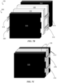
- FIGS. 45 A- 45 B show perspective schematic illustrations of an exemplary battery comprising electrochemical cells, according to some embodiments.
- FIG. 46 shows a perspective schematic illustration of an exemplary battery comprising electrochemical cells, thermally conductive solid article portions comprising alignment features, and a thermally insulating compressible solid article portion, according to some embodiments.
- FIGS. 47 A- 47 E show schematic diagrams of components of an exemplary battery, according to some embodiments.
- Batteries including electrochemical cells, associated components, and arrangements thereof are generally described.
- batteries with phase change materials that can facilitate heat transfer within the battery (e.g., from an electrochemical cell to a component of a housing of the battery) are described.
- the phase change material is in thermal communication with a thermally conductive solid article portion (e.g., a cooling fin).
- the batteries include a multiplexing switch apparatus. Such a multiplexing switch apparatus may be used to selectively discharge one or more electrochemical cells of the battery.
- batteries with housings that undergo relatively little expansion and contraction even in cases where electrochemical cells in the battery undergo a relatively high degree of expansion and contraction during charging and discharging are provided.
- Batteries configured to apply relatively high magnitudes and uniform force to electrochemical cells in the battery, while in some cases having high energy densities and a relatively low pack burden, are also provided.
- arrangements of electrochemical cells and associated components are generally described.
- thermally conductive solid articles that can be used for aligning components of the battery are described.
- thermally insulating and compressible components for battery packs are generally described.
- the present disclosure describes multiple inventive aspects relating to battery components and arrangements thereof, application of force to multiple electrochemical cells in battery packs, and thermal management. These inventive aspects can, alone or in combination, lead to the manufacture of batteries with unexpected properties such as unexpectedly high energy densities and durability.
- applying an anisotropic force with a component normal to at least one of the electrochemical cells can improve performance during charging and/or discharging by reducing problems such as dendrite formation and surface roughening of the electrode while improving current density.
- at least one of the electrochemical cells of the battery comprises lithium metal or a lithium metal alloy as an electrode active material.
- Lithium metal may undergo dendrite growth, for example, which can in certain cases lead to failure of the electrochemical cell and safety hazards.
- Application of relatively high magnitudes of anisotropic force to electrodes comprising lithium metal may mitigate lithium dendrite formation and other deleterious phenomena.
- the present disclosure provides methods, articles, and devices that can, in some cases, be used to mitigate such dimensional changes of the overall battery (e.g., the housing) even in situations where electrochemical cells may expand and contract.
- relatively high magnitudes of force e.g., defining a pressure of greater than or equal to 10 kg f /cm 2 and up to 40 kg f /cm 2 , or greater than or equal to 10 kg f /cm 2 and up to 25 kg f /cm 2
- relatively high magnitudes of force e.g., defining a pressure of greater than or equal to 10 kg f /cm 2 and up to 40 kg f /cm 2 , or greater than or equal to 10 kg f /cm 2 and up to 25 kg f /cm 2
- relatively high magnitudes of force e.g., defining a pressure of greater than or equal to 10 kg f /cm 2 and up to 40 kg f /cm 2 , or greater than or equal to
- relatively high magnitudes of force may be applied relatively uniformly using certain housing components (e.g., solid plates) having relatively high stiffness while being lightweight (e.g., certain types of carbon fiber having certain weaves and thicknesses).
- certain articles in the battery may compensate for dimensional changes of the electrochemical cells (e.g., thermally insulating compressible solid article portions such as microcellular elastomeric foams).
- thermally insulating compressible solid article portions such as microcellular elastomeric foams.
- thermally insulating compressible solid article portions may then be capable of serving multiple roles: compensating for dimensional changes in electrochemical cells and mitigating heat transfer between electrochemical cells. It has also been discovered that aligning components (e.g., electrochemical active regions of the electrochemical cells) of the battery can lead to improved performance and durability (e.g., by increasing the uniformity of the pressure distribution experienced by the electrochemical active regions).
- aligning components e.g., electrochemical active regions of the electrochemical cells
- Certain aspects of the present disclosure are related to thermally conductive solid article portions that can be used to align electrochemical active regions of the battery while also performing other functions, such as facilitating heat transfer away from the electrochemical cells (e.g., laterally).
- the use of articles capable of alignment and thermal transfer may reduce the number of components needed for the battery, which may reduce complexity, pack burden, and/or costs.
- Certain aspects also relate to unconventional arrangements of components that can simultaneously mitigate multiple potentially deleterious phenomena associated with batteries comprising multiple electrochemical cells, while using relatively few components, which may allow for relatively high energy densities while also allowing for good durability.
- certain arrangements of electrochemical cells, thermally conductive solid article portions, and thermally insulating compressible solid article portions may promote unexpectedly efficient heat transfer away from the electrochemical cells while also facilitating compensation for applied forces and cell breathing and facilitating relatively uniform pressure distributions (e.g., within ⁇ 2.5 kg f /cm 2 or within ⁇ 2 kg f /cm 2 across an electrochemical active region).
- batteries are generally described.
- the battery may include, in some embodiments, one or more rechargeable electrochemical cells.
- the battery comprises one or more rechargeable lithium-ion electrochemical cells.
- FIGS. 1 A- 1 B are cross-sectional schematic diagrams of a non-limiting embodiment of battery 100 .
- the battery may comprise one or more electrochemical cells as well as one or more other components (e.g., articles stacked with the electrochemical cells, housings, electrical and thermal management equipment, etc.).
- the battery comprises multiple electrochemical cells, including a first electrochemical cell and a second electrochemical cell.
- battery 100 in FIGS. 1 A- 1 B comprises first electrochemical cell 110 and second electrochemical cell 120 at least partially enclosed by optional housing 102 .
- the battery may have any of a variety of suitable configurations including, but not limited to, a stacked configuration, a folded configuration, or a wound configuration.
- at least one electrochemical cell of the battery (e.g., first electrochemical cell, second electrochemical cell) comprises lithium and/or a lithium metal alloy as an electrode active material.
- electrochemical cells in the battery comprise at least one anode.
- FIG. 2 shows a schematic diagram of one exemplary embodiment of first electrochemical cell 110 comprising anode 112 .
- the anode comprises an anode active material.
- an “anode active material” refers to any electrochemically active species associated with an anode.
- the anode comprises lithium metal and/or a lithium metal alloy as an anode active material.
- anode 112 comprises lithium metal and/or a lithium metal alloy as an anode active material in some embodiments.
- An electrode such as an anode can comprise, in accordance with certain embodiments, lithium metal and/or a lithium metal alloy as an electrode active material during at least a portion of or during all of a charging and/or discharging process of the electrochemical cell.
- the anode is or comprises vapor-deposited lithium (e.g., a vapor-deposited lithium film). Additional suitable anode active materials are described in more detail below. Certain embodiments described herein may be directed to systems, devices, and methods that may allow for improved performance (e.g., magnitude and uniformity of applied force, thermal management, alignment of electrochemical active regions to promote uniformity of lithium deposition during charging) of electrochemical devices comprising certain anodes, such as lithium metal-containing anodes.
- electrochemical cells in the battery comprise at least one cathode.
- first electrochemical cell 110 comprises cathode 114 .
- the cathode can comprise a cathode active material.
- a “cathode active material” refers to any electrochemically active species associated with a cathode.
- the cathode active material may be or comprise a lithium intercalation compound (e.g., a metal oxide lithium intercalation compound).
- cathode 114 in FIG. 2 comprises a nickel-cobalt-manganese lithium intercalation compound. Suitable cathode materials are described in more detail below.
- cathode refers to the electrode in which an electrode active material is oxidized during charging and reduced during discharging
- anode refers to the electrode in which an electrode active material is reduced during charging and oxidized during discharging.
- electrochemical cells in the battery comprise a separator between the anode and the cathode.
- FIG. 2 shows exemplary separator 115 between anode 112 and cathode 114 , according to certain embodiments.
- the separator may be a solid electronically non-conductive or insulative material that separates or insulates the anode and the cathode from each other, preventing short circuiting, and that permits the transport of ions between the anode and the cathode.
- the separator is porous and may be permeable to an electrolyte.
- first electrochemical cell and the second electrochemical cell have the same types of components (e.g., same anode active material, same cathode active material, same type of separator), in other embodiments the first electrochemical cell has one or more different components than the second electrochemical cell (e.g., a different anode active material, a different cathode active material, a different type of separator). In some embodiments, the first electrochemical cell and the second electrochemical cell are identical in composition and/or dimensions.
- the battery comprises a phase change material portion.
- a phase change material portion generally refers to an object comprising a substance that releases/absorbs sufficient thermal energy at a phase transition (e.g., from a solid to a liquid and vice versa) to facilitate cooling and/or heating.
- the amount of thermal energy released/absorbed depends on the latent heat associated with the substance from which the phase transition material is made, which can readily be determined by those of ordinary skill in the art.
- phase change material portions into batteries can facilitate relatively rapid removal of relatively large amounts heat from components of the batteries (e.g., electrochemical cells) during operation (e.g., charging and/or discharging).
- Such cooling may, in some instances, reduce deleterious phenomena associated with over-heating of certain electrochemical cells (e.g., cells comprising lithium as an electrode active material), such as reduced durability, cycle life, capacity, and even safety concerns such as thermal runaway.
- FIG. 3 shows a cross-sectional schematic of a stack 100 of electrochemical cells comprising first electrochemical cell 110 , second electrochemical cell 120 , and phase change material portion 160 .
- Stack of electrochemical cells 100 may be part of a battery (e.g., a rechargeable battery).
- a thermally conductive solid article portion may be at least partially between the first electrochemical cell and the second electrochemical cell.
- thermally conductive solid article portion 131 is at least partially between first electrochemical cell 110 and second electrochemical cell 120 . Further details, properties, and form factors for the thermally conductive solid article portion are described below.
- the phase change material portion is in thermal communication with the thermally conductive solid article portion.
- phase change material portion 160 may be in thermal communication with thermally conductive solid article portion 131 .
- two points are said to be in thermal communication when there exists at least one pathway that connects the two points and extends only through solid material having a thermal conductivity of greater than or equal to 0.5 W m ⁇ 1 K ⁇ 1 at a temperature of 25° C.
- the thermally-conductive solid article portion (e.g., in thermal communication with the phase change material portion) may be in thermal communication with an electrochemical cell (e.g., the first electrochemical cell and/or the second electrochemical cell).
- the stack When arranged in this manner, the stack may be arranged such that heat can dissipate from the electrochemical cell (e.g., during cycling), through at least a portion of the thermally conductive solid article, and to the phase change material portion. Such an arrangement may promote relatively efficient cooling of the electrochemical cell.
- at least a portion of the thermally conductive solid article portion is in direct contact with at least a portion (e.g., a pouch) of the electrochemical cell.
- the thermally conductive solid article portion be may in direct contact with the phase change material portion and the electrochemical cell.
- the phase change material portion comprises fatty acids (e.g., lauric acid, stearic acid).
- the phase change material comprises an inorganic compound.
- the phase change material may comprise an inorganic salt.
- inorganic salt hydrates e.g., sodium sulfate decahydrate, sodium chloride sodium sulfate decahydrate, manganese nitrate hexahydrate, sodium silicate pentahydrate.
- the phase change material comprises a composite material. Some such phase change materials are generally non-flammable, low-cost, and readily commercially available.
- a lateral positioning of the phase change material portion can reduce or eliminate pressure experienced by the phase change material portion due to that applied anisotropic force.
- Having the phase change material portion in thermal communication with a thermally conductive solid article portion that is in turn in thermal communication with the electrochemical cell may facilitate satisfactory thermal transfer (e.g., cooling during cycling) even in instances where the phase change material portion is lateral to the electrochemical cell (as opposed to part of the stack).
- the phase change material portion is lateral to an electrode active surface (e.g., an anode active surface and/or cathode active surface) of the electrochemical cell.
- the phase change material portion is lateral to all electrode active surfaces (e.g., an anode active surface and/or cathode active surface) of a stack of electrochemical cells.
- at least 50 volume percent (vol %), at least 75 vol %, at least 90 vol %, at least 95 vol %, at least 99 vol % or all of the phase change material portion is lateral to at least 50 vol %, at least 75 vol %, at least 90 vol %, at least 95 vol %, at least 99 vol % or all of the electrochemical cell.
- a region of the thermally conductive solid article portion is lateral to the first electrochemical cell.
- region 193 of thermally conductive solid article portion 131 is lateral to first electrochemical cell 110 .
- the phase change material portion (e.g., phase change material portion 160 ) is relatively close to a region of the thermally conductive solid article portion that is lateral to the first electrochemical cell.
- at least a portion of the phase change material portion may be within 5 cm, within 2 cm, with 1 cm, within 5 mm, within 2 mm, within 1 mm, within 0.5 mm, or less of a region of the thermally conductive solid article portion.
- at least a portion of the phase change material portion is in direct contact with a region of the thermally conductive solid article portion (e.g., a region lateral to the first electrochemical cell).
- the battery comprises a housing.
- the housing may at least partially enclose other components of the battery.
- the housing may at least partially enclose the first electrochemical cell and the second electrochemical cell.
- FIG. 1 A shows optional housing 102 at least partially enclosing first electrochemical cell 110 and second electrochemical cell 120 , according to certain embodiments.
- the housing may comprise rigid components.
- the housing may comprise one or more solid plates.
- the solid plate may, for example, be an endplate.
- FIG. 4 A shows a cross-sectional schematic diagram of exemplary battery 100 comprising housing 202 , housing 202 comprising first solid plate 201 and second solid plate 203 . Further details of certain solid plates that may be used in the battery are described below.
- the housing does not comprise a solid plate.
- the solid surface and other components of a containment structure configured to house the electrochemical device are part of a unitary structure.
- Some embodiments are related to applying, during at least one period of time during charge and/or discharge of the electrochemical cells (e.g., first electrochemical cell, second electrochemical cell), an anisotropic force with a component normal to an electrode active surface of at least one electrochemical cell of the battery.
- an anisotropic force may reduce potentially deleterious phenomena associated with certain types of electrochemical cells (e.g., cells comprising lithium metal as an electrode active material) and improve utilization.
- applying an anisotropic force with a component normal to an active surface of an electrode of the electrochemical device can reduce problems (such as surface roughening of the electrode and dendrite formation) while improving current density.
- Application of such forces to multiple electrochemical cells of a battery pack may present certain challenges, including uniformity of pressure distribution for each electrochemical cell, which can be important for both performance and durability. Certain aspects described herein may, in some cases, address and overcome such challenges.
- FIG. 1 A depicts a schematic cross-sectional illustration of a force that may be applied to the first electrochemical cell and the second electrochemical cell in the direction of arrow 181 .
- Arrow 182 illustrates the component of force 181 that is normal to an active surface of first electrochemical cell 110 , according to certain embodiments.
- active surface is used to describe a surface of an electrode that can be in physical contact with an electrolyte when the article is part of an electrochemical cell, and at which electrochemical reactions may take place.
- the housing of the battery is configured to apply, during at least one period of time during charge and/or discharge of the first electrochemical cell and/or the second electrochemical cell, an anisotropic force having a relatively high magnitude component normal to electrode active surfaces of at least one (or all) of the electrochemical cells in the battery.
- the housing of the battery is configured to apply, during at least one period of time during charge and/or discharge of the first electrochemical cell and/or the second electrochemical cell, an anisotropic force having a relatively high magnitude component normal to the first electrode active surface and the second electrode active surface.
- the housing may be configured to apply such a force in a variety of ways.
- the housing comprises two solid articles (e.g., a first solid plate and a second solid plate as shown in FIG. 4 A , where housing 202 comprises first solid plate 201 and second solid plate 203 ).
- An object e.g., a machine screw, a nut, a spring, etc.
- the electrochemical cells and other components of the battery may be compressed between the plates (e.g., a first solid plate and a second solid plate) upon rotating the screw.
- one or more wedges may be displaced between the housing and a fixed surface (e.g., a tabletop, etc.).
- the force may be applied by driving the wedge between the housing (e.g., between a solid plate of a containment structure of the housing) and the adjacent fixed surface through the application of force on the wedge (e.g., by turning a machine screw).
- Some embodiments comprise applying an anisotropic force with a component normal to a first electrode active surface of the first electrochemical cell and/or a second electrode active surface of the second electrochemical cell defining a pressure of at least 10 kg f /cm 2 , at least 12 kg f /cm 2 , at least 20 kg f /cm 2 , and/or up 25 kg f /cm 2 , or more.
- the housing is configured to apply such anisotropic forces. While high magnitudes of anisotropic force with a component normal to an electroactive surface can improve performance, too high of a magnitude of force may cause problems such as damage to certain components of the battery (e.g., the thermally insulating compressible solid article portion described below).
- some embodiments comprise applying (e.g., via the housing) during at least one period of time during charge and/or discharge of the first electrochemical cell and/or the second electrochemical cell, an anisotropic force with a component normal to a first electrode active surface of the first electrochemical cell and/or a second electrode active surface of the second electrochemical cell defining a pressure of less than or equal to 40 kg f /cm 2 , less than or equal to 35 kg f /cm 2 , less than or equal to 30 kg f /cm 2 , less than or equal to 25 kg f /cm 2 , or less.
- Combinations of these ranges e.g., at least 10 kg f /cm 2 and less than or equal to 40 kg f /cm 2 , at least 10 kg f /cm 2 and less than or equal to 25 kg f /cm 2 , or at least 12 kg f /cm 2 and less than or equal to 30 kg f /cm 2 are possible.
- Some embodiments comprise applying a first anisotropic force with a component normal to a first electrode active surface of the first electrochemical cell and/or a second electrode active surface of the second electrochemical cell defining a pressure having a first magnitude of at least 10 kg f /cm 2 (e.g., at least 12 kg f /cm 2 ), and then also during a charge and/or discharge of the battery, applying a second anisotropic force with a component normal to a first electrode active surface of the first electrochemical cell and/or a second electrode active surface of the second electrochemical cell defining a pressure having a second magnitude that is at least 10 kg f /cm 2 , at least 12 kg f /cm 2 , or higher and less than or equal to 40 kg f /cm 2 , less than or equal to 30 kg f /cm 2 , or less.
- the second magnitude of pressure is greater than the first magnitude by a factor of at least 1.2, at least 1.5, at least 2, at least 2.5, and/or up to 3, or up to 4.
- the second magnitude may be higher than the first magnitude, for example, in some embodiments where the first magnitude of force is applied via the housing (e.g., a rigid housing) and during a charging and/or discharge process, expansion of one or more components of the battery (e.g., one or more electrochemical cells) causes the force experienced by the electrochemical cells to increase.
- the first magnitude occurs when the electrochemical cells are at a state of charge (SOC) of less than or equal to 10%, less than or equal to 5%, less than or equal to 2%, less than or equal to 1%, or 0%.
- the second magnitude occurs when the electrochemical cells are at a state of charge of greater than or equal to 50%, greater than or equal to 75%, greater than or equal to 90%, greater than or equal to 95%, greater than or equal to 99%, or 100%. Combinations of these ranges are possible.
- the first magnitude occurs when the electrochemical cells are at a state of charge of less than or equal to 10% and the second magnitude (e.g., that defines a pressure that is greater than that of the first magnitude by a factor of at least 1.2 and up to 4) occurs when the electrochemical cells are at a state of charge of greater than or equal to 50%.
- the magnitude of anisotropic force defines a pressure of 12 kg f /cm 2 at a 0% SOC and 30 kg f /cm 2 at a 100% SOC.
- the battery comprises one or more solid plates.
- the housing is configured to apply the anisotropic force via a solid plate.
- the solid plates may be, for example, endplates configured to apply an anisotropic force to the electrochemical cells (e.g., first electrochemical cell, second electrochemical cell).
- first solid plate 201 and second solid plate 203 are endplates.
- the surfaces of a solid plate do not necessarily need to be flat.
- one of the sides of the solid plate may comprise a surface that is curved (e.g., contoured, convex) in the absence of an applied force.
- the solid plate e.g., an aluminum solid plate
- the end plate is convex with respect to the electrochemical cells in the absence of an applied force, and under at least one magnitude of applied force the end plate may become less convex (e.g., become flat).
- the housing may comprise any suitable solid material.
- a solid plate of the housing and/or stack is or comprises a metal, metal alloy, composite material, or a combination thereof.
- the metal that the solid plate is or comprises is a transition metal.
- the solid article is or comprises Ti, Cr, Mn, Fe, Co, Ni, Cu, or a combination thereof.
- the solid plate is or comprises a non-transition metal.
- the solid article is or comprises Al, Zn, or combinations thereof.
- Exemplary metal alloys that the solid plate can be or comprise include alloys of aluminum, alloys of iron (e.g., stainless steel), or combinations thereof.
- Exemplary composite materials that the solid plate can be or comprise include, but are not limited to, reinforced polymeric, metallic, or ceramic materials (e.g., fiber-reinforced composite materials), carbon-containing composites, or combinations thereof.
- a solid plate (e.g., solid plate 201 ) of the housing and/or stack comprises carbon fiber.
- Carbon fiber may be present in the solid plate in a relatively high amount (e.g., greater than or equal to 50 wt %, greater than or equal to 75 wt %, greater than or equal to 90 wt %, greater than or equal to 95 wt %, greater than or equal to 99 wt %, 100 wt %).
- Carbon fiber can, in some cases, afford relatively high stiffness and/or strength while having a relatively low mass (e.g., by having a relatively low mass density).
- the carbon fiber comprises unidirectional carbon fiber.
- at least one layer (or all layers) of the carbon fiber material of the solid plate is unidirectional within the layer. While relatively thin and/or twill weave carbon fiber materials are known, it has been discovered herein that unidirectional carbon fiber laminates may afford relatively beneficial properties (e.g., high stiffness and/or strength, low deflection under load).
- the housing comprises a solid plate comprising carbon fiber, the solid plate having a thickness of at least 5 mm, at least 8 mm, at least 10 mm, and/or up to 12 mm, up to 15 mm, up to 20 mm, or more.
- the solid plate comprises multiple layers of carbon fiber (e.g., unidirectional carbon fiber).
- the solid plate of the housing comprises a first layer comprising carbon fibers substantially parallel to a first direction in the plane of the first layer and a second layer comprising carbon fibers substantially parallel to a second direction in the plane of the second layer.
- two lines in a plane can be substantially parallel if, for example, the maximum angle defined by the two lines is less than or equal to 10°, less than or equal to 5°, less than or equal to 2°, or less than or equal to 1°.
- the angle between the first direction and the second direction may be an angle ⁇ .
- the pattern can be represented as “[ ⁇ °/ ⁇ ].”
- ⁇ is greater than or equal to (i.e., more positive than) ⁇ 90°, greater than or equal to ⁇ 75°, greater than or equal to ⁇ 60°, greater than or equal to ⁇ 45°, greater than or equal to ⁇ 30°, greater than or equal to ⁇ 15°, or greater, and/or less than or equal to 90°, less than or equal to 75°, less than or equal to 60°, less than or equal to 45°, less than or equal to 30°, less than or equal to 15°, or less.
- first solid plate 201 comprises first layer 211 comprising carbon fibers 218 substantially parallel to first direction 204 , second layer 212 comprising carbon fibers 218 substantially parallel to second direction 206 , and third layer 213 comprising carbon fibers 218 substantially parallel to first direction 204 .
- the solid plate of the housing may comprise, in order: a first layer comprising carbon fibers substantially parallel to a first direction in the plane of the first layer, a second layer comprising carbon fibers substantially parallel to a second direction in the plane of the second layer substantially perpendicular (e.g., within 10°, within 5°, within 2°, within 1° of perpendicular) to the first direction, and a third layer comprising carbon fibers substantially parallel to the first direction.
- ⁇ is within 10°, within 5°, within 2°, within 1° of 90°.
- Each of the individual layers may have a unidirectional weave.
- first solid plate 201 comprises first layer 211 comprising carbon fibers 218 substantially parallel to first direction 204 , second layer 212 comprising carbon fibers 218 substantially parallel to second direction 206 , which is substantially perpendicular to first direction 204 , and third layer 213 comprising carbon fibers 218 substantially parallel to first direction 204 , according to some embodiments. It has been observed that, in some cases, carbon fiber materials having such a “[0°/90°/0°]” orientation of layers may have higher strength and/or stiffness than other types of carbon fiber materials. While FIG. 4 B shows an embodiment of solid plate 201 comprising three layers, more layers are possible.
- the solid plate further comprises, in order, a fourth layer comprising carbon fibers substantially parallel to the second direction and a fifth layer comprising carbon fibers parallel to the first direction.
- FIG. 4 C shows one such embodiment, where first solid plate 201 comprises first layer 211 comprising carbon fibers 218 substantially parallel to first direction 204 , second layer 212 comprising carbon fibers 218 substantially parallel to second direction 206 , which is substantially perpendicular to first direction 204 , third layer 213 comprising carbon fibers 218 substantially parallel to first direction 204 , fourth layer 214 comprising carbon fibers 218 substantially parallel to second direction 206 , and fifth layer 215 comprising carbon fibers 218 substantially parallel to first direction 204 .
- the solid plate of the housing comprises at least 1, at least 2, at least 3, at least 5, at least 10, at least 15, and/or up to 20, up to 25, up to 50, up to 60, up to 75, or more layers of carbon fiber (e.g., layered carbon fiber with oriented fibers) as described herein. Some or all of these layers (e.g., oriented layers) may have certain mechanical properties described below (e.g., modulus).
- the multiple layers of carbon fiber comprise, in order: a first layer comprising carbon fibers substantially parallel to a first direction in the plane of the first layer, a second layer comprising carbon fibers substantially parallel (e.g. within 10°, within 5°, within 2°, within 1° of parallel) to a second direction in the plane of the second layer, a third layer comprising carbon fibers substantially parallel to the first direction in the plane of the third layer, a fourth layer comprising carbon fibers substantially parallel (e.g. within 10°, within 5°, within 2°, within 1° of parallel) to a third direction in the fourth layer, and a fifth layer comprising carbon fibers substantially parallel to the first direction in the plane of the fifth layer.
- the angle between the first direction and the second direction may be an angle ⁇
- the angle between the first direction and the third direction may be an angle ⁇ .
- the pattern can be represented as “[0°/ ⁇ /0°/ ⁇ /0°].” It should be understood that when notation of this form is used, the direction of each layer may be within 100 (i.e., +/ ⁇ 10°) of the direction denoted by the angle value in the notation.
- a layer orientation having repeating units in which the first layer is at 0°, the second layer is at ⁇ , the third layer is at 5°, the fourth layer is at ⁇ , and the fifth layer is at ⁇ 10° would be considered to have a “[0°/ ⁇ /0°/ ⁇ /0°]” layer orientation pattern because each layer is within 100 of the value indicated by the notation.
- Each of the individual layers may have a unidirectional weave.
- ⁇ is greater than or equal to (i.e., more positive than) ⁇ 90°, greater than or equal to ⁇ 75°, greater than or equal to ⁇ 60°, greater than or equal to ⁇ 45°, greater than or equal to ⁇ 30°, greater than or equal to ⁇ 15°, or greater, and/or less than or equal to 90°, less than or equal to 75°, less than or equal to 60°, less than or equal to 45°, less than or equal to 30°, less than or equal to 15°, or less. Combinations of these ranges (e.g., ⁇ greater than or equal to ⁇ 90° and less than or equal to 90°) are possible.
- first solid plate 201 comprises first layer 211 comprising carbon fibers 218 substantially parallel to first direction 204 , second layer 212 comprising carbon fibers 218 substantially parallel to second direction 206 , third layer 213 comprising carbon fibers 218 substantially parallel to first direction 204 , fourth layer 214 comprising carbon fibers 218 substantially parallel to third direction 220 , and fifth layer 215 comprising carbon fibers 218 substantially parallel to first direction 204 .
- FIG. 4 F shows angle ⁇ between first direction 204 and second direction 206 and angle ⁇ between first direction 204 and third direction 220 for the embodiment illustrated in FIG. 4 G .
- solid articles such as solid plates having some such patterns of unidirectional carbon fiber layers demonstrate less deflection under applied load than otherwise identical solid articles such as solid plates lacking such patterns (e.g., solid plates in which the carbon fibers of each layer are all substantially parallel).
- the solid plate comprises at least 1, at least 2, at least 3, at least 5, at least 10, at least 15, and/or up to 20, up to 25, up to 50, up to 60, up to 75, or more layers comprising carbon fiber having a tensile modulus of less than or equal to 650 GPa, less than or equal to 600 GPa, less than or equal to 550 GPa or less, and a flexural modulus of less than or equal to 650 GPa, less than or equal to 600 GPa, less than or equal to 550 GPa or less at room temperature (25° C.).
- the electrochemical cells of the battery may undergo a cumulative expansion that is relatively large, while an expansion of the battery is relatively small. It has been discovered that certain inventive aspects of the present disclosure, such as the application of relatively high magnitudes of force to multiple electrochemical cells, the use of strong and/or stiff housings (e.g., comprising certain carbon fiber plates), and the use of compressible components such as the thermally insulating compressible solid article portions described below, may afford such a small (or no) expansion of the battery even when the electrochemical cells expand to a relatively large extent.
- the electrochemical cells undergo a cumulative expansion during the charging and/or discharging of greater than 1 mm, greater than or equal to 1.2 mm, greater than or equal to 1.5 mm, greater than or equal to 2 mm, greater than or equal to 5 mm, greater than or equal to 10 mm, greater than or equal to 12 mm, and/or up to 20 mm, up to 30 mm, or more, and an expansion of the battery during the charging and/or discharging is less than or equal to 1 mm, less than or equal to 0.75 mm, less than or equal to 0.5 mm, and/or as low as 0.2 mm, as low as 0.1 mm, or less.
- the cumulative expansion of the electrochemical cells may be in any of the above-mentioned ranges, while the battery does not expand at all.
- one or more components of the battery e.g., a compressible component such as a thermally insulating compressible solid article portion
- each electrochemical cell expands by at least 1 mm. In some embodiments, the cumulative expansion of the electrochemical cells is at least 12 mm.
- the battery has a relatively small volume. It has been observed that certain aspects described herein, alone or in combination, such as the solid plates comprising carbon fiber, the solid housing components described in more detail below, the thermally insulating compressible solid article portions, and the thermally conductive solid article portions, can allow for relatively high magnitudes of force and/or relatively high energy densities for the battery, even with a relatively small volume.
- the battery has a volume of less than or equal to 15000 cm 3 , less than or equal to 13500 cm 3 , less than or equal to 12000 cm 3 , less than or equal to 10000 cm 3 , less than or equal to 8000 cm 3 , less than or equal to 6750 cm 3 , less than or equal to 6000 cm 3 , less than or equal to 5000 cm 3 , and/or as low as 4000 cm 3 , or lower.
- certain configurations of the housing may provide for an ability to enclose a relatively large amount of electrochemical cell volume and/or apply relatively high force while having a relatively small housing volume.
- the battery has a relatively high energy density, as described above. In some embodiments, the battery has a specific energy of greater than or equal to 250 Wh/kg. In some embodiments, the battery has a specific energy of greater than or equal to 280 Wh/kg, greater than or equal to 290 Wh/kg, greater than or equal to 300 Wh/kg, and/or up to 320 Wh/kg, up to 350 Wh/kg, or more. In some embodiments, the battery has a volumetric density of greater than or equal to 230 Wh/L, greater than or equal to 250 Wh/L, greater than or equal to 280 Wh/L, and/or up to 300 Wh/L, or higher.
- the battery may have a relatively high energy density and/or apply a relatively high magnitude of force while having a relatively low pack burden (defined as one minus the mass of the electrochemical cells of the battery divided by the total mass of the battery).
- pack burden 1 ⁇ (mass of the electrochemical cells/mass of the battery).
- the battery has a pack burden of less than or equal to 50%, less than or equal to 45%, less than or equal to 40%, less than or equal to 35%, less than or equal to 30%, and/or as low as 25%, as low as 20%, or lower.
- the battery includes components configured such that the battery (or portions of the battery) has a relatively low volume for a given size of electrochemical cells, compared to other configurations. Having a relatively low housing volume while having relatively large electrochemical active regions of cells may afford relatively large volumetric energy densities. Relatively large volumetric energy densities may be advantageous in certain applications where limited space for batteries is available, but where a large amount of stored energy may be desired, such as certain battery-powered vehicles. It has been realized that certain existing housings configured to apply anisotropic forces may have arrangements or operate under mechanisms that require relatively large spatial profiles. For example, housings configured to apply anisotropic forces to electrochemical cells via solid plates generally include fasteners spanning between solid plates.
- Tension in the fasteners may contribute some or all of the force applied to the cells within the housings.
- the battery in FIG. 4 A is one such example.
- the use of fasteners for applying tension when applying force via solid plates generally requires a relatively large lateral extension of pressure-applying components of the housing past lateral dimensions of electrochemical active regions of the electrochemical cells.
- Such “overhang” of housing components with respect to the cells may contribute to a large volume of the overall housing and battery.
- Certain embodiments herein are directed to application of force to electrochemical cells (e.g., the first electrochemical cell, the second electrochemical cell) with relatively low lateral extension of solid plates and/or pressure-applying components.
- the battery comprises a stack comprising electrochemical cells (e.g., the first electrochemical cell, the second electrochemical cell).
- the stack may be a multicomponent stack comprising non-cell components such as thermally insulating compressible solid article portions, thermally conductive solid article portions, and/or sensors.
- the stack includes a solid plate.
- the stack is at least partially enclosed by a housing comprising a solid plate. The solid plate may cover at least a portion (e.g., at least 10%, at least 25%, at least 50%, at least 75%, at least 90%, at least 95%, or all) of an end of the stack.
- a portion of a surface (e.g., an end of a stack) of an object is considered covered by a second object in this context if there exists a line perpendicular to and extending out of the portion of the surface and away from a bulk of the object that intersects any of the second object.
- any stack of components e.g., cells
- any stack of components includes two ends: the first end corresponds to the external surface of the first component (e.g., first cell) that faces away from the bulk of the stack, and the second end corresponds to the external surface of the last component (e.g., last cell) that faces away from the bulk of the stack.
- the first end corresponds to the external surface of the first component (e.g., first cell) that faces away from the bulk of the stack
- the second end corresponds to the external surface of the last component (e.g., last cell) that faces away from the bulk of the stack.
- the anisotropic force may define a pressure of at least 10 kg f /cm 2 , at least 12 kg f /cm 2 , at least 20 kg f /cm 2 , and/or up to 25 kg f /cm 2 , up to 30 kg f /cm 2 , up to 35 kg f /cm 2 , up to 40 kg f /cm 2 , or more.
- the solid housing component may contribute to force application by being coupled to a first solid plate (e.g., covering at least a portion of a first end of the stack, or a solid plate between the solid housing component and the first electrochemical cell) and a second component of the housing covering at least a portion of a second end of the stack (e.g., a second solid plate or a part of a frame).
- a first solid plate e.g., covering at least a portion of a first end of the stack, or a solid plate between the solid housing component and the first electrochemical cell
- a second component of the housing covering at least a portion of a second end of the stack (e.g., a second solid plate or a part of a frame).
- housing 302 comprises solid housing component 314 coupled to first solid plate 310 and second solid plate 312 (which covers second end 308 of stack 304 ).
- Tension in solid housing component 314 may contribute force causing first solid plate and/or second solid plate 312 to compress stack 304 , thereby applying an anisotropic force in direction of arrow 182 having component 182 normal to a first electrode active surface of first electrochemical cell 110 and/or a second electrode active surface of second electrochemical cell 120 .
- housing 302 comprises solid plate 310 having largest lateral dimension 328 , as illustrated by the dashed line with arrows.
- Solid plate 310 may be a first solid plate, and housing 302 may further comprise second solid plate 312 coupled to first solid plate via solid housing component 314 .
- FIG. 6 C illustrates the concept of a lateral pressure-applying dimension of a housing.
- Battery 100 comprises housing 302 comprising solid plate 310 , solid housing component 314 , and electronics component 332 coupled to solid plate 310 and positioned along a side of stack 304 .
- Housing 302 has largest lateral pressure-applying dimension 328 between far corners of solid plate 310 . (although this matches the largest lateral dimension of solid plate 310 in the pictured embodiment, such an occurrence is not necessary, as in other embodiments parts beyond the solid plate may be pressure-applying and contribute to a largest lateral pressure-applying dimension).
- the housing may have a largest lateral pressure-applying dimension that is relatively small with respect to an electrochemical active region of one or more of the electrochemical cells in the battery. Having a relatively small lateral pressure-applying profile of the housing may stand in contrast to certain existing pressure-applying housings having larger lateral pressure-applying profiles (e.g., due to lateral space needed for load-applying fasteners to pass through one or more components of the housing such as a solid plate). Certain embodiments of this disclosure are directed to various techniques and configurations that can make housings having relatively small lateral pressure-applying profiles practical (e.g., via certain configurations of solid housing components). Small pressure-applying regions of housings (relative to the electrochemical cells) may afford overall batteries having relatively small volumes, which can be advantageous in some applications.
- a ratio of the largest lateral pressure-applying dimension to the largest lateral dimension of the first electrochemical active region and/or a ratio of the largest lateral pressure-applying dimension of the solid plate to the largest lateral dimension of the second electrochemical active region is less than or equal to 1.6, less than or equal to 1.5, less than or equal to 1.4, less than or equal to 1.3, less than or equal to 1.2, less than or equal to 1.1, less than or equal to 1.05, less than or equal to 1.02, less than or equal to 1.01, and/or as low as 1.005, as low as 1.001, or as low as 1.
- At least 90%, at least 95%, at least 99%, or all of the first electrochemical active region of the first electrochemical cell and/or the second electrochemical active region of the second electrochemical cell is covered by a portion of the housing within the largest lateral pressure-applying dimension of the housing.
- the solid housing component may couple (or contribute to coupling of) the solid plate covering at least a portion of a first end of the stack to a component of the housing covering at least a portion of second end of the stack. Such a coupling via the solid housing component (e.g., solid housing component 314 ) may contribute to the anisotropic force applied by the housing.
- the solid housing component spans from the solid plate to the second end of the stack. For example, in FIG. 5 , solid housing component 314 spans from first solid plate to second end 308 of stack 304 .
- an object spanning from a first element to a second element may extend past some or all of either the first element of the second element, provided that it reach at least a portion of each the two elements in the direction of the spanning.
- solid housing component 314 which reaches all of but does not extend past solid plate 310 and extends past second end 308 , is considered to span from solid plate 310 to second end 308 .
- the housing comprises a first solid plate covering at least a portion of the first end of the stack and a second solid plate covering at least a portion of the second end of the stack (e.g., as shown in FIG. 5 )
- the solid housing component spans from the first solid plate to the second solid plate.
- Solid housing components may join two or more parts of the housing via any of a variety of coupling techniques.
- the solid housing components may be part of the underlying structure of the housing.
- the housing comprises a frame at least partially enclosing the stack, and a solid housing component is a part of the frame (e.g., a side of the frame joining two ends of the frame).
- the housing may have a single solid housing component, or the housing may comprise multiple solid housing components.
- the housing comprises a first solid housing component along a first side of the stack and a second solid housing component on along a second (e.g., opposite) side of the stack.
- Housing 302 in FIG. 5 shows one such embodiment, where first solid housing component 314 and optional second solid housing component 316 are along opposite sides of stack 304 .
- no auxiliary fastener spanning from the solid plate toward the second end of the stack along a side of the stack is in tension during application of the anisotropic force.
- An auxiliary fastener in this context is a fastener that is not part of the underlying housing structure.
- rod 205 is not part of the underlying structure of housing 202 and is therefore considered an auxiliary fastener.
- FIG. 4 A where housing 202 comprises first solid plate 201 coupled to second solid plate 203 via a fastener in the form of rod 205 , rod 205 is not part of the underlying structure of housing 202 and is therefore considered an auxiliary fastener.
- rod 205 is not part of the underlying structure of housing 202 and is therefore considered an auxiliary fastener.
- housing 302 comprises first solid plate 310 and second solid plate 312 coupled via solid housing component 314 , which is part of an underlying structure of housing 302 and is therefore not considered an auxiliary fastener.
- a housing in which no auxiliary fastener spans from the solid plate toward the second end of the stack along a side of the stack is in tension during application of the anisotropic force may still be able to apply the anisotropic force to the electrochemical cells of the stack even without tension from an auxiliary fastener at least because of the presence of a solid housing component in tension coupled to the solid plate, as described above and below.
- the housing may require less lateral extension (“overhang”) of pressure-applying components such as solid plates compared to housings that employ auxiliary fasteners in tension for force application. As discussed, less lateral extension beyond electrochemical active areas of the electrochemical cell may contribute to lower overall housing and battery volumes (and higher volumetric energy density).
- no auxiliary fastener spans from the solid plate to the second end of the stack. For example, in FIG. 5 , no auxiliary fastener spans from solid plate 310 to second end 308 of stack 304 , in accordance with some embodiments. In some embodiments, no auxiliary fastener passes through a thickness of the solid plate.
- fasteners may be present in the housing.
- fasteners couple the solid housing component to the solid plate or a solid portion adjacent to the solid plate, as described in more detail below.
- the solid housing component may be made of any of a variety of materials, depending on desired properties of the solid housing component and/or the overall battery.
- the solid housing component may be made of any of the materials described above for the solid plate.
- the solid housing component comprises a metal (e.g., aluminum, titanium, etc.), metal alloy (e.g., stainless steel), composite, polymeric material (e.g., a rigid plastic), or combination thereof.
- a metal e.g., aluminum, titanium, etc.
- metal alloy e.g., stainless steel
- composite e.g., polymeric material (e.g., a rigid plastic), or combination thereof.
- some (e.g., at least 50 wt %, at least 75 wt %, at least 90 wt %, at least 95 wt %, at least 99 wt %) or all of the solid housing component may be metal, metal alloy, polymeric material, composite, or a combination thereof.
- a metal alloy that may be suitable for the solid housing component is 5052-H32 aluminum, which is an aluminum alloy in which aluminum is primarily alloyed with magnesium and chromium and has been strained hardened and thermally stabilized.
- Other non-limiting examples of potentially suitable metals and/or metal alloys include, but are not limited to, steel (e.g., mild steel, high strength steel, stainless steel) and titanium alloys that can withstand the pressures defined by the applied anisotropic forces described in this disclosure (e.g., greater than or equal to 10 kg f /cm 2 and/or up to 40 kg f /cm 2 or higher).
- the solid housing component comprises a composite material.
- the solid housing component comprises a material (e.g., a composite comprising carbon fiber) having a relatively high modulus. In some embodiments, the solid housing component has a relatively high tensile modulus and a relatively high flexural modulus.
- some or all of the solid housing component has a tensile modulus of at least 1 GPa, at least 5 GPa, at least 10 GPa, at least 20 GPa, at least 50 GPa, at least 75 GPa, at least 100 GPa, 120 GPa, at least 150 GPa, at least 200 GPa, at least 300 GPa, at least 500 GPa and/or up to 550 GPa, up to 600 GPa, up to 650 GPa, or greater, and a flexural modulus of at least 120 GPa at least 150 GPa, at least 200 GPa, at least 300 GPa, at least 500 GPa and/or up to 550 GPa, up to 600 GPa, up to 650 GPa, or greater at room temperature (25° C.).
- the solid housing component comprises layers comprising a material (e.g., a composite comprising carbon fiber), and one or more of the layers has a relatively high tensile modulus and a relatively high flexural modulus.
- the solid housing component comprises layers comprising a material (e.g., a composite comprising carbon fiber), one or more of the layers having a tensile modulus of at least 120 GPa, at least 150 GPa, at least 200 GPa, at least 300 GPa, at least 500 GPa or greater, and a flexural modulus of at least 120 GPa at least 150 GPa, at least 200 GPa, at least 300 GPa, at least 500 GPa or greater at room temperature (25° C.).
- the solid housing component comprises layers comprising a material (e.g., a composite comprising carbon fiber), one or more of the layers having a tensile modulus of less than or equal to 650 GPa, less than or equal to 600 GPa, less than or equal to 550 GPa or less, and a flexural modulus of less than or equal to 650 GPa, less than or equal to 600 GPa, less than or equal to 550 GPa or less at room temperature (25° C.).
- a material e.g., a composite comprising carbon fiber
- the solid housing component has a relatively large number of layers satisfying the modulus ranges above.
- the solid housing component comprises at least 1, at least 2, at least 3, at least 5, at least 10, at least 15, and/or up to 20, up to 25, up to 50, up to 60, up to 75, or more layers comprising a material (e.g., a composite comprising carbon fiber) having a tensile modulus of at least 120 GPa, at least 150 GPa, at least 200 GPa, at least 300 GPa, at least 500 GPa or greater, and a flexural modulus of at least 120 GPa at least 150 GPa, at least 200 GPa, at least 300 GPa, at least 500 GPa or greater at room temperature (25° C.).
- a material e.g., a composite comprising carbon fiber
- the solid housing component comprises at least 1, at least 2, at least 3, at least 5, at least 10, at least 15, and/or up to 20, up to 25, up to 50, up to 60, up to 75, or more layers comprising a material (e.g., a composite comprising carbon fiber) having a tensile modulus of less than or equal to 650 GPa, less than or equal to 600 GPa, less than or equal to 550 GPa or less, and a flexural modulus of less than or equal to 650 GPa, less than or equal to 600 GPa, less than or equal to 550 GPa or less at room temperature (25° C.).
- a material e.g., a composite comprising carbon fiber
- a substantial portion of the housing comprises a material (e.g., a composite comprising carbon fiber) having a relatively high modulus.
- a material having a flexural and/or tensile modulus of at least 120 GPa, at least 150 GPa, at least 200 GPa, at least 300 GPa, at least 500 GPa, and/or up to 550 GPa, up to 600 GPa, up to 650 GPa, or higher is present in the housing in an amount of at least 50 wt %, at least 75 wt %, at least 90 wt %, at least 95 wt %, or more.
- the housing comprises a material having a relatively high modulus may be advantageous because they facilitate batteries with a relatively small lateral profile, a relatively high volumetric energy density, and/or adequate resistance to deformation (e.g., upon application of force).
- the housing comprises a solid plate and a solid housing component, each comprising a composite material having a relatively high modulus, such as a composite comprising carbon fiber, it can be beneficial to have some housing components with planarity parallel to a first plane and other housing components with planarity not parallel to that first plane.
- a solid plate of the housing may have multiple layers of unidirectional carbon fiber having planarity parallel to a plane of the solid plate, as well as a solid housing component (e.g., a frame component spanning from the solid plate to a second end of the stack) having multiple layers of unidirectional carbon fiber with planarity nonparallel to (e.g., substantially perpendicular to) the plane of the solid plate.
- a solid housing component e.g., a frame component spanning from the solid plate to a second end of the stack
- the solid housing component has a relatively high modulus, such a property is not necessary in all embodiments.
- the solid housing component has a tensile strength sufficient to avoid observable deflection and/or failure when the housing applies the anisotropic force to the electrochemical cells.
- the solid housing component has a tensile strength in at least one dimension of at least 10 MPa, at least 20 MPa, at least 50 MPa, at least 100 MPa, at least 200 MPa, at least 500 MPa, at least 1 GPa, at least 2 GPa, at least 5 GPa, and/or up to 10 GPa, up to 20 GPa, up to 50 GPa, up to 100 GPa, up to 120 GPa, or higher.
- components of the housing of the battery are reinforced by local increases in thickness and/or the attachment of mechanical doublers.
- local increases in thickness and/or the attachment of mechanical doublers provide additional support for portions of the housing (e.g., solid housing components along a side of the stack) that are pressure-applying or are otherwise mechanically loaded under at least some configurations of the housing.
- local increases in thickness and/or the attachment of mechanical doublers facilitate a reduction in the largest lateral pressure applying dimension of the housing and/or increase the gravimetric and/or volumetric energy density of the battery.
- a local increase in thickness or a mechanical doubler may have an area of less than 100%, less than or equal to 90%, less than or equal to 75%, less than or equal to 50%, less than or equal to 25%, less than or equal to 10%, less than or equal to 5%, or less of a corresponding solid housing component.
- a thickness of the solid housing component at a local increase in thickness and/or a combined thickness of a solid housing component and a mechanical doubler may be greater than an average thickness of the solid housing component by a factor of greater than or equal to 1.05, greater than or equal to 1.1, greater than or equal to 1.25, greater than or equal to 1.5, greater than or equal to 2, and/or up to 3, up to 5, or greater.
- FIGS. 8 D- 8 E introduce an exemplary embodiment of battery 100 , where mechanical doubler 315 is attached to solid housing component 314 .
- FIG. 8 D presents an exploded perspective schematic diagram of the battery
- FIG. 8 E presents a perspective schematic diagram of the battery. Note that while any feature appearing in FIGS. 8 D- 8 E may appear in some embodiments, some embodiments can include fewer than all pictured features while still accomplishing any of a variety of the advantages and performances described above.
- the solid housing component may have any of a variety of lengths while maintaining rigidity.
- such a rigidity even at relatively long lengths affords an ability for the ratio of the distance between a solid plate and the second end of the stack to the largest lateral dimension of the housing to be relatively large if desired.
- such a large ratio may allow for a relatively large number (e.g., at least 6, at least 12, or more) of electrochemical cells to be included in the stack of the battery.
- Such an ability for relatively long housing components spanning the stack stands in contrast to traditional auxiliary fasteners such as rods or bolts with nuts. Tension in long fasteners may produce bending moments that result in deleterious deflection.
- Solid housing components may not appreciably deflect under such tension.
- the ratio of the distance between a solid plate and the second end of the stack to the largest lateral dimension of the battery is less than or equal to 20, less than or equal to 10, less than or equal to 5, less than or equal to 2, less than or equal to 1.5, less than or equal to 1, less than or equal to 0.5, less than or equal to 0.2, less than or equal to 0.1, or less.
- housings with any given ratio of the distance between a solid plate and the second end of the stack to the largest lateral dimension of the housing can be reconfigured to have a new ratio of the distance between the solid plate and the second end of the stack to largest lateral dimension of the battery by modifying and/or adjusting one or more solid housing components of the housing.
- a variety of solid housing components for spanning along a side of the stack of the battery can be interchanged to accommodate a variety of ratios of the distance between a solid plate and the second end of the stack to the largest lateral pressure-applying dimension, in some embodiments.
- the ability to reconfigure the length of the housing without the adjustment of auxiliary fasteners can facilitate a reduction in the largest lateral pressure applying dimension of the battery. In some embodiments, the ability to reconfigure the length of the housing in such a way advantageously reduces the number of parts of the housing.
- the housing comprises a lateral base portion proximate to and/or along a lateral edge of the solid plate.
- the lateral base portion is part of the solid plate.
- the lateral base portion is part of a solid housing component coupled to the solid plate.
- batteries can be mounted to an external surface using fasteners (e.g., auxiliary fasteners).
- the lateral base portion is configured for mounting the battery to an external surface. For batteries that lack a lateral base portion, additional portions of the solid plate may be required to mount the battery to an external surface, and these may increase the lateral profile of the battery.
- the effective thermal conductivity of an article generally refers to the ability of an article to conduct heat, taking into account that the article may be made of a single material or of a non-homogeneous material that includes a combination of materials (e.g., a composite material such as a particulate material or layered material).
- An exemplary method for measuring the thermal conductivity or effective thermal conductivity solid housing component is using a hot disk method, as described in ISO/DIS 22007-2.2.
- a solid housing component (e.g., first solid housing component, second solid housing component) has an effective thermal conductivity of greater than or equal to 10 W m ⁇ 1 K ⁇ 1 , greater than or equal to 25 W m ⁇ 1 K ⁇ 1 , greater than or equal to 50 W m ⁇ 1 K ⁇ 1 , greater than or equal to 65 W m ⁇ 1 K ⁇ 1 , greater than or equal to 80 W m ⁇ 1 K ⁇ 1 , greater than or equal to 100 W m ⁇ 1 K ⁇ 1 , greater than or equal to 138 W m ⁇ 1 K ⁇ 1 , greater than or equal to 150 W m ⁇ 1 K ⁇ 1 , and/or up to 159 W m ⁇ 1 K ⁇ 1 , up to 200 W m ⁇ 1 K ⁇ 1 , or greater in an in-plane direction and/or in a thickness direction at a temperature of 25° C.
- a solid housing component e.g., first solid housing component, second solid housing component
- a solid housing component may be made of aluminum (e.g., aluminum metal) and have an effective thermal conductivity of 159 W m ⁇ 1 K ⁇ 1 in an in-plane direction and/or in a thickness direction at a temperature of 25° C.
- a solid housing component e.g., first solid housing component, second solid housing component
- a relatively large percentage of the stack of the battery is covered by the housing of the battery. This may, in some cases, be advantageous because it can afford substantial protection to the battery (e.g., from impact during handling and/or use).
- the housing covers at least 30%, at least 50%, at least 70%, at least 90%, at least 95%, at least 99%, or 100% of an external surface area of the stack.
- the solid housing component may couple to the solid plate of the housing in any of a variety of suitable ways. It has been realized that certain coupling techniques may establish coupling while maintaining relatively small lateral profiles for the housing. In some embodiments, mechanically interlocking features of the solid housing component and a lateral edge of the solid plate establish a joint.
- any of a variety of suitable joints may be employed via the interlocking features.
- any of a variety of woodworking joints may be suitable. It should be understood that woodworking joints refer to the geometries and balances of forces associated with the joints, and it is not required that any part of two components joined with a woodworking joint actually be made of wood. Examples of types of joints that may be established by interlocking features of the solid housing component and a lateral edge of the solid plate include, but are not limited to, box joints, dovetail joints, splice joints (e.g. tabled splice joints), and Knapp joints.
- a joint between the solid housing components and the solid plate of the housing is formed at least in part between a projection of the solid housing component (or solid plate) and a recess of the solid plate (or solid housing component).
- Some such embodiments may involve the solid housing comprising a projection, the solid plate comprising a recess, and the solid housing component and the solid plate being configured to form a joint at least in part via coupling of the projection and the recess.
- exemplary battery 100 may be configured such that first solid housing component 314 has first projection 340 and optional second projection 342 , while optional second solid housing component 316 has third projection 344 and fourth projection 346 .
- a housing of this type may, in some embodiments, decrease a largest lateral pressure-applying dimension of the housing relative to a housing comprising, for example, auxiliary fasteners coupling solid plates. Additionally, use of mechanically interlocking features (e.g., for woodworking joints) for coupling may require a lower part count than housings that employ auxiliary fasteners (e.g., nuts and bolts) for coupling.
- the solid housing component and the solid plate are configured to be joined via a dovetail joint (e.g., via tapered projects and/or recesses in the solid housing component and solid plate).
- the solid housing component may comprise male dovetail features at an end of the solid housing component
- the solid plate may comprise a female dovetail feature (e.g., proximate to a lateral edge of the solid plate).
- the male and female features may mate to form a joint.
- FIG. 7 A shows a side view schematic illustration of exemplary battery 100 , where all recesses are identical and where all projections are identical, in accordance with some embodiments.
- FIG. 7 B shows an exploded schematic illustration of exemplary battery 100 of this type, also revealing optional third solid housing component 318 and optional fourth solid housing component 320 .
- FIG. 7 C shows a perspective schematic illustration of exemplary battery 100 .
- the solid housing component comprises recesses which can couple, at least in part, with projections of the solid plates to form joints.
- the solid housing component and the solid plate may further be coupled via, for example, an adhesive and/or a weld (e.g., at a joint formed by the interlocking features).
- the lateral portion of the solid plate may apply a force to at least a portion of the solid plate.
- tension in first solid housing component 304 may cause lateral portion 370 to press against exterior surface 335 of solid plate 310 , thereby causing stack 304 to experience an anisotropic compressive force having a component in the direction of arrow 182 in FIG. 9 A ).
- the lateral portion of the solid housing component may have any of a variety of shapes depending on, for example, a desired deflection of the solid plate and/or pressure distribution within the battery. It has been realized that some shapes of lateral portions (e.g., relatively flat portions) can distribute force (e.g., from tension in the solid housing component) across the face of the solid plate more uniformly than, for example, solid plates coupled via discrete auxiliary fasteners (e.g., bolts with nuts) in contact with relatively small areas of the solid plate.
- a housing of this type may, in some embodiments, decrease a largest lateral pressure-applying dimension of the housing relative to a housing comprising, for example, auxiliary fasteners coupling solid plates.
- FIG. 9 A shows a front view schematic illustration of exemplary battery 100 in one embodiment, where all the lateral portions are identical.
- FIG. 9 B shows an exploded schematic illustration of the same exemplary battery 100
- FIG. 9 C shows a perspective schematic illustration of the same exemplary battery 100 . It should be understood that other embodiments, where lateral portions have different geometries from each other, are possible, as are embodiments with more or fewer solid housing components and/or lateral portions of solid housing components.
- the solid housing component contributes to force application by covering at least a portion (e.g., at least 10%, at least 25%, at least 50%, at least 75%, at least 90%, at least 95%, or all) of a first end of the stack comprising the first electrochemical cell and the second electrochemical cell. While in some embodiments a solid housing component directly covers at least a portion of an end of the stack (e.g., is directly adjacent), in some embodiments, the solid housing component covers at least a portion of an intervening component (e.g., a first solid plate) or part of a housing frame covering at least a portion of the end of the stack.
- an intervening component e.g., a first solid plate
- the first solid housing component covers a portion (e.g., at least 10%, at least 25%, at least 50%, at least 75%, at least 90%, at least 95%, or all) of the first end of the stack and has a portion along at least some of the side of the stack.
- a second solid housing component covers at least a portion (e.g., at least 10%, at least 25%, at least 50%, at least 75%, at least 90%, at least 95%, or all) of the second end of the stack a portion along at least some of the side of the stack.
- the first solid housing component and second solid housing component may be coupled directly or indirectly. Such a coupling be accomplished in any of a variety of suitable ways.
- a point of attachment between the first solid housing component and the second solid housing component is at a region of overlap between the first solid housing component and the second solid housing component along the side of the stack. It should be understood that a point of attachment may be part of a region of attachment between two surfaces (e.g., a region along a line of attached points, or a region occupying a 2-dimensional set of attached points), and is not meant to apply that an entirety of attachment is limited to a single point.
- first solid housing component 314 and second solid housing component 316 are coupled at point of attachment 382 at region of overlap 384 along side 380 of stack 304 , in accordance with some embodiments.
- a similar point of attachment may be present at a region of overlap at an opposite side of the stack.
- a housing of this type may, in some embodiments, decrease a largest lateral pressure-applying dimension of the housing relative to a housing comprising, for example, auxiliary fasteners coupling solid plates.
- the stack comprises one or more solid plates.
- a solid plate of the same type as solid plate 310 in FIG. 5 may be between first solid housing component 314 and first electrochemical cell 110 .
- the solid plate may be a first solid plate, and the stack may further comprise a second solid plate between the second solid housing component and the second electrochemical cell.
- the external anisotropic force may define a pressure of at least 10 kg f /cm 2 , at least 12 kg f /cm 2 , at least 20 kg f /cm 2 , and/or up to 25 kg f /cm 2 , up to 30 kg f /cm 2 , up to 35 kg f /cm 2 , up to 40 kg f /cm 2 , or more.
- first solid housing component 314 may be welded (e.g., laser welded) to second solid housing component 316 at point of attachment 382 at region of overlap 384 along side 308 of stack 304 (e.g., during application of an external anisotropic force in direction 181 having component 182 normal to an electrode active surface of first electrochemical cell 110 ).
- attaching the first solid housing component to the second solid housing component or to one or more additional solid housing comprises applying a fastener (e.g., a screw, a rivet, etc.) to the first housing component and the second housing component.
- attaching the first solid housing component to the second solid housing component or to one or more additional solid housing comprises applying an adhesive to the first housing component and the second housing component, thereby forming an adhesive interaction.
- attaching a solid housing component to the first solid plate and/or the second solid plate comprises establishing a joint by mechanically interlocking features of the solid housing component and a lateral edge of the first solid plate and/or second solid plate.
- some embodiments include removing the applied external anisotropic force while maintaining, via tension in the attached first solid housing component and the second solid housing component, an anisotropic force having a component normal to the first electrode active surface and/or the second electrode active surface.
- the anisotropic force may have a component normal to the first electrode active surface of the first electrochemical cell of the stack and/or the second electrode active surface of the second electrochemical cell of the stack.
- the anisotropic force may define a pressure of at least 10 kg f /cm 2 , at least 12 kg f /cm 2 , at least 20 kg f /cm 2 , at and/or up to 25 kg f /cm 2 , up to 30 kg f /cm 2 , up to 35 kg f /cm 2 , up to 40 kg f /cm 2 , or more. It has been realized that by applying an initial force to the stack and subsequently establishing tension in one or more parts of the housing (e.g., a solid housing component and/or a solid plate), relatively high pressures may be established in the stack at a point of manufacture within a substantially fixed housing.
- the housing e.g., a solid housing component and/or a solid plate
- Some such configurations may reduce a number of parts required for the overall battery, e.g., by avoiding use of tension in auxiliary fasteners (e.g., with separate screws or threaded rods, nuts, washers, etc.).
- a reduction in number of parts and/or fasteners in the housing may promote an overall reduction in housing and/or battery volume, which may be desirable in some applications.
- a ratio of at least one (or all) lateral dimensions of the solid housing component to the thickness of the solid housing component is greater than or equal to 1.5, greater than or equal to 2, greater than or equal to 5, greater than or equal to 10, greater than or equal to 20, greater than or equal to 50, greater than or equal to 100, greater than or equal to 500, and/or up to 1000, up to 5000, or greater.
- the solid housing component e.g., comprising a solid sheet
- the solid housing component (e.g., comprising a solid sheet) has a thickness of less than or equal to 5 mm, less than or equal to 2 mm, less than or equal to 1 mm, less than or equal to 500 microns, and/or as low as 200 microns or less.
- the solid housing component (e.g., first solid housing component, second solid housing component) comprises a metal and/or metal alloy sheet, such as an aluminum (e.g., aluminum metal) sheet.
- the solid housing component e.g., first solid housing component, second solid housing component
- the battery further comprises a contoured solid article portion between a lateral exterior surface of the first electrochemical cell and a portion of the housing.
- the contoured solid article portion may comprise a surface adjacent (e.g., directly adjacent or indirectly adjacent) to the lateral exterior surface of the first electrochemical cell that is convex with respect to the lateral exterior surface in the absence of an applied force. In some embodiments, under at least one magnitude of applied force, the surface of the contoured solid article portion becomes less convex.
- battery 100 may comprise contoured solid article portion 402 between lateral exterior surface 403 of electrochemical cell 110 and a portion of housing 102 , in accordance with certain embodiments.
- contoured solid article portion 402 which is adjacent to lateral exterior surface 403 , is convex with respect to lateral exterior surface 403 in the absence of an applied force.
- the contoured solid article portion is a discrete article with respect to the housing.
- the contoured solid article portion may be between the lateral exterior surface of the first electrochemical cell and, for example, a solid plate of the housing and/or a solid housing component described above.
- the surface of the contoured solid article portion becomes less convex.
- a change in convexity may be caused by force-induced deformation of the contoured solid article portion.
- the surface of the contoured solid article portion may become less convex.
- a solid surface that has a given shape “in the absence of an applied force” is one that, when all external forces are removed from the object comprising that surface, always assumes that particular shape. Accordingly, a surface that has a convex shape in the absence of an applied force is one that always assumes a convex shape when all external forces are removed from the object comprising that surface.
- a first surface is convex with respect to a second surface when the first surface curves away from the second surface. It should be understood that portions of surfaces being convex with respect to other surfaces refers to the external geometric surface of the portion.
- An external geometric surface of an object refers to the surface defining the outer boundaries of the object when analyzed on substantially the same scale as the maximum cross-sectional dimension of the object. Generally, the external geometric surface of an object does not include the internal surfaces, such as the surface defined by pores within a porous object.
- a contoured solid article portion can promote a desired pressure distribution experienced by one or more (or all) of the active surfaces of the electrochemical cells of the battery. For example, in some cases, a uniform pressure distribution is achieved. Such desired pressure distributions can, in some cases, lead to improved performance of the battery.
- the deformation of the contoured solid article portion (e.g., to become less convex) under applied force may, in some instances, reduce potentially deleterious effects in pressure distribution caused by deformation (e.g., deflection) of portions of the housing (e.g., solid plates) during application of pressure.
- Further description of contoured surfaces and related devices and methods is provided in International Publication No. WO2020/257414, published on Dec. 24, 2020, and entitled “Methods, Systems, and Devices for Applying Forces to Electrochemical Devices,” filed as International Application No. PCT/US2020/038375 on Jun. 18, 2020, which is incorporated herein by reference in its entirety.
- the contoured solid article portion (e.g., that is part of a device configured to apply a force to an electrochemical device) comprises any suitable solid material.
- the contoured solid article portion is or comprises a metal, metal alloy, composite material, or a combination thereof.
- the metal that the contoured solid article portion is or comprises is a transition metal.
- the contoured solid article portion is or comprises Ti, Cr, Mn, Fe, Co, Ni, Cu, or a combination thereof.
- the contoured solid article portion is or comprises a non-transition metal.
- the contoured solid article portion is or comprises Al, Zn, or combinations thereof.
- the contoured solid article portion comprising the solid surface comprises a polymeric material (e.g., an organic polymeric material).
- the contoured solid article portion comprises a polymeric material (e.g., an organic polymeric material) in an amount of greater than or equal to 25 weight percent (wt %), greater than or equal to 50 wt %, greater than or equal to 75 wt %, greater than or equal to 90 wt %, greater than or equal to 95 wt %, greater than or equal to 99 wt %, or up to 100 wt %.
- Example of suitable polymeric materials include, but are not limited to, acrylonitrile butadiene styrene, polylactic acid, polyamide, polyether ether ketone, Nylon, polycarbonate, polyetherimide resin, or combinations thereof.
- a contoured solid article portion comprising a polymeric material may be relatively inexpensive to fabricate and may deform relatively easily compared to other types of materials.
- the contoured solid article portion may have any of a variety of suitable elastic moduli.
- the elastic modulus of the contoured solid article portion may be high enough such that it can adequately hold its shape.
- the contoured solid article portion has an elastic modulus of greater than or equal to 10 MPa, greater than or equal to 50 MPa, greater than or equal to 100 MPa, greater than or equal to 200 MPa, greater than or equal to 500 MPa, greater than or equal to 1 GPa, greater than or equal to 2 GPa, greater than or equal to 5 GPa, greater than or equal to 10 GPa, greater than or equal to 20 GPa, greater than or equal to 50 GPa, greater than or equal to 100 GPa, greater than or equal to 200 GPa, or greater.
- the contoured solid article portion comprising the solid surface has an elastic modulus of less than or equal to 800 GPa, less than or equal to 760 GPa, less than or equal to 500 GPa, less than or equal to 400 GPa, less than or equal to 300 GPa, less than or equal to 250 GPa, less than or equal to 200 GPa, less than or equal to 150 GPa, less than or equal to 100 GPa, less than or equal to 75 GPa, less than or equal to 50 GPa, less than or equal to 25 GPa, less than or equal to 10 GPa, less than or equal to 5 GPa, or lower).
- First solid housing component 314 and second solid housing component 316 are coupled (e.g., via laser welding) at point of attachment 382 in region of overlap 384 along side 380 of stack 304 , according to some embodiments.
- phase change material portion 160 is in thermal communication with thermally conductive solid 131 , which is at least partially between first electrochemical cell 110 and second electrochemical cell 120 . While in some embodiments the phase change material portion is lateral to one or more electrochemical cells of a stack in a battery (e.g., as shown with phase change material portion 160 in FIG. 14 ), other configurations are possible, such as configurations in which the phase change material portion is a layer within the stack.
- the phase change material is in thermal communication with the thermally conductive solid article (and in some instances consequently in thermal communication with an electrochemical cell of the stack) via at least a portion (e.g., at least 0.01%, at least 0.1%, at least 1%, at least 10%, at least 50%, at least 75% or more by surface area) of the side of the stack.
- phase change material portion 160 is in thermal communication with thermally conductive solid article portion 131 via at least a portion of side 380 due to the lateral positioning of phase change material portion 131 .
- the stack comprises one or more solid plates (e.g., a first solid plate, a second solid plate).
- a first solid plate between an electrochemical cell (e.g., an outermost electrochemical cell of the stack) and the first solid housing component.
- a second solid plate between an electrochemical cell (e.g., an outermost electrochemical cell of the stack) and the second solid housing component.
- FIG. 15 shows a cross-sectional schematic diagram on one such embodiment, which is configured similarly to that shown in FIG. 14 , but further has first solid plate 310 between first electrochemical cell 110 and first solid housing component 314 , and has second solid plate 312 between second electrochemical cell 120 and second solid housing component 316 .
- the phase change material portion is located such that it experiences a relatively low pressure compared to an average pressure defined by the anisotropic force experienced by the electrode active surface.
- application of an anisotropic force with a component normal to an electrode active surface of an electrochemical cell may improve performance and/or durability of the cell (e.g., when the cell comprises lithium (e.g., lithium metal and/or a lithium alloy) as an electrode active material).
- a magnitude of pressure sufficient to cause improved performance of the electrochemical cell may cause adverse effects on some phase change materials (e.g., mechanical failure due to compressive stress).
- phase change material portion and an electrochemical cell can be arranged such that the relatively efficient heat transfer from the electrochemical cell to the phase change material portion can occur but without the phase change material portion experiencing as high a pressure as does the electrochemical cell.
- lateral positioning of the phase change material portion relative to the electrochemical cell e.g., lateral to a stack comprising the electrochemical cell
- phase change material portion 160 can, in some instances, result in the phase change material portion experiencing less pressure than does an electrode active surface of electrochemical cell during application of anisotropic force 181 .
- Such an arrangement stands in contrast to arrangements where, for example, a phase change material portion is part of a stack comprising the electrochemical cell, or where the phase change material forms a matrix into which an array of electrochemical cells are embedded. In those arrangements, the pressure experienced by the electrochemical cell would be substantially similar to the pressure experienced by the phase change material portion.
- the phase change material portion is located such that during at least some period of time during which the housing applies the anisotropic force with a component normal to an electrode active surface of the electrochemical cell, some (e.g., at least 25 vol %, at least 50 vol %, at least 75 vol %, at least 90 vol %, at least 95 vol %, at least 99 vol % or more) or all of the phase change material portion experiences a pressure defined by the anisotropic force that is zero or at least 50%, at least 75%, at least 90%, at least 95%, or at least 99% lower than an average pressure defined by the anisotropic force experienced by the electrode active surface.
- the thermally conductive solid article portion (e.g., first thermally conductive solid article portion, second thermally conductive solid article portion) is or comprises a fin (e.g., a metal and/or metal alloy fin).
- the thermally conductive solid article portion (e.g., first thermally conductive solid article portion, second thermally conductive solid article portion) is or comprises a solid plate. It should be understood that the surfaces of a sheet, fin, or solid plate do not necessarily need to be flat. For example, one of the sides of a sheet, fin, or solid plate could have any of the non-planarities and/or alignment features described herein.
- the thermally conductive solid article portion may have a thickness as well as two orthogonal lateral dimensions that are orthogonal to each other as well as orthogonal to the thickness.
- first thermally conductive solid article portion 131 has maximum thickness 235 , lateral dimension 151 , and a second lateral dimension (not pictured) orthogonal to both maximum thickness 235 and lateral dimension 151 (which would run into and out of the plane of the drawing in FIG. 16 A ).
- the dimensions of the thermally conductive solid article portion may be chosen based on any of a variety of considerations. For example, the thickness or lateral dimensions may be chosen based on the desired total size of the battery and/or a desired pack burden. In some embodiments, one or more lateral dimensions of the thermally conductive solid article portion is such that heat generated by the electrochemical cells, once conducted to the thermally conductive solid article portions, can be transferred a relatively long distance from the electrochemical active regions of the electrochemical cells.
- the thermally conductive solid article portion has one or more lateral dimensions that extends at least 1 mm, at least 2 mm, at least 5 mm, at least 1 cm, at least 2 cm, at least 5 cm, and/or up to 10 cm or more past the electrochemical active region of the electrochemical cell coupled to the thermally conductive solid article portion.
- the thermally conductive solid article portion (e.g., first thermally conductive solid article portion, second thermally conductive solid article portion) has at least one lateral dimension that is at least 5 times, at least 10 times, and/or up to 20 times, up to 50 times, up to 100 times or more greater than the maximum thickness of the thermally conductive solid article portion.
- the battery comprises a thermally insulating compressible solid article portion.
- the thermally insulating compressible solid article portion may be between two electrochemical cells of the battery.
- battery 100 comprises thermally insulating compressible solid article portion 140 between first electrochemical cell 110 and second electrochemical cell 120 , according to certain embodiments.
- thermally insulating compressible solid article portions is described below.
- the thermally conductive solid article portion is relatively smooth as compared to the thermally insulating compressible solid article portion. This may, in some cases, be advantageous, because, under high magnitudes of force, surface irregularities in certain types of thermally insulating compressible solid article portions (e.g., microcellular foams) may cause non-uniform pressure distributions on the electrode active surfaces of the battery.
- a relatively smooth thermally conductive solid article portion e.g., a metal sheet
- surface 144 of thermally insulating compressible solid article portion 140 may be relatively rough (e.g., have a relatively high surface roughness), while surface 334 of first thermally conductive solid article portion 131 may be relatively smooth (e.g., have a relatively low surface roughness), thereby mitigating irregularities in pressure distribution to surface 116 of first electrochemical cell 110 .
- the thermally conductive solid article portion has a surface facing a surface of the first electrochemical device having a surface roughness of less than or equal to 10 micrometers, less than or equal to 5 micrometers, less than or equal to 1 micrometer, less than or equal to 0.5 micrometers, less than or equal to 0.1 micrometers, less than or equal to 0.05 micrometers, less than or equal to 0.01 micrometers, or less.
- the thermally conductive solid article portion has a surface facing a surface of the first electrochemical device having a surface roughness as low as 0.005 micrometers. That is to say, in some embodiments, the thermally conductive solid article portion has a surface having a surface roughness as low as 0.005 micrometers, with that surface facing a surface of the first electrochemical device.
- battery 400 comprises first electrochemical cell 110 , first thermally conductive solid article portion 131 , first thermally insulating compressible solid article portion 140 , second thermally conductive solid article portion 132 , second electrochemical cell 120 , third thermally conductive solid article portion 231 , second thermally insulating compressible solid article portion 240 , fourth thermally conductive solid article portion 232 , and third electrochemical cell 210 .
- FIG. 21 is a schematic diagram of a non-limiting embodiment of battery 100 .
- Battery 100 in FIG. 21 comprises first electrochemical cell 110 and second electrochemical cell 120 as part of a stack with first thermally conductive solid article portion 131 and second thermally conductive solid article portion 132 , in accordance with certain embodiments.
- the thermally conductive solid article portions may comprise alignment features, as described in more detail below.
- FIG. 21 shows an embodiment where battery 100 comprises first electrochemical cell 110 comprising first electrochemical active region 190 and second electrochemical cell 120 comprising second electrochemical active region 192 .
- An electrochemical active region refers to a region defined by the overlap of the anode active surfaces of the anodes and cathode active surfaces of the cathodes of the electrochemical cell.
- first electrochemical cell 110 has electrochemical active region 190 defined by the overlap of anode active surface 166 and cathode active surface 167 .
- active surface is used to describe a surface of an electrode that can be in physical contact with an electrolyte when the article is part of an electrochemical cell, and at which electrochemical reactions may take place.
- a portion of an anode and/or cathode may not be part of the electrochemical active region of the electrochemical cell.
- an anode and cathode may be offset such that a portion of an anode does not overlap with the corresponding cathode, thereby preventing that portion of the anode from participating in electrochemical reactions with the cathode. Referring to FIG.
- portion 168 of anode 112 does not overlap with any of cathode 114 and therefore cannot participate in any electrochemical reactions with cathode 114 , and therefore portion 118 of anode 112 is not part of first electrochemical active region 190 , according to certain embodiments.
- an electrochemical cell of the battery (e.g., first electrochemical cell, second electrochemical cell) is coupled to a non-planarity of a thermally conductive solid article portion (e.g., first thermally conductive solid article portion, second thermally conductive solid article portion) of the battery.
- FIG. 21 shows one non-limiting such example, where battery 100 comprises first electrochemical cell 110 coupled to non-planarity 161 of first thermally conductive solid article portion 131 and battery 100 further comprises second electrochemical cell 120 coupled to non-planarity 163 of second thermally conductive solid article portion 132 .
- Any of a variety of non-planarities may be part of a thermally conductive solid article portion and used to couple to an electrochemical cell.
- a non-planarity of a thermally conductive solid article portion may be a deviation from the mean plane of a surface of the thermally conductive solid article portion facing the electrochemical cell to which it is coupled.
- thermally conductive solid article portions may comprise alignment features that interlock with features of the housing.
- an alignment feature such as non-planarity (e.g. a ridge) of a solid housing component of a housing may interlock with alignment features such as grooves of the thermally conductive solid article portions.
- alignment may be achieved without the incorporation of alignment features, due to geometric constraints imposed by the housing (e.g., by one or more solid housing components described above) on components of the battery. Aligning components of the battery with the housing may prove advantageous to some embodiments by facilitating a reduction in the number of constituent parts of the housing, reducing a largest lateral pressure applying dimension of the housing, and/or increasing the battery's volumetric energy density.
- battery 100 comprises first electrochemical cell 110 , first thermally conductive solid article portion 131 , first thermally insulating compressible solid article portion 140 , second electrochemical cell 120 , second thermally conductive solid article portion 132 , second thermally insulating compressible solid article portion 240 , and third electrochemical cell 210 .
- the battery may not be limited to three electrochemical cells, and may comprise at least 2, at least 3, at least 4 at least 5, at least 8, at least 10, and/or up to 12, up to 15, up to 20, up to 24, up to 30, up to 40, up to 48, or more electrochemical cells.
- the total number of thermally insulating compressible solid article portions is equal to one more than the total number of electrochemical cells in the battery (e.g., 12 electrochemical cells and 13 thermally insulating compressible solid article portions).
- multiple thermally conductive solid articles are in thermal communication with phase change material portion.
- the stack of the battery comprises the following in order:
- phase change material portions are part of the same solid body.
- at least two (e.g., at least three, or all four) of the first phase change material portion, the second phase change material portion, the third phase change material portion, and the fourth phase change material portion are part of the same solid body.
- first phase change material portion 160 and second phase change material portion 260 may be connected via an additional phase change material portion (not pictured) in FIG. 26 .
- One non-limiting way of achieving such variance in density is by including holes/gaps in the thermally insulating compressible article portion such that the overall external geometric dimensions of the thermally insulating compressible solid article portion are suitable for performing some or all of the roles described herein, while a mass of the thermally insulating compressible solid article is reduced. It has been observed that some such configurations may provide for a relative reduction in the mass of the battery (and an increase in energy density) without significantly affecting performance of the battery.
- the thermally insulating compressible solid article portion (e.g., comprising an open-cell solid such as an open-cell foam) has a relatively high porosity. Having a relatively high porosity may contribute to the thermally insulating compressible solid article portion having a relatively low density, which in some instances can be advantageous as described above. A high porosity may also contribute, in some cases, to a relatively high compressibility. In some embodiments, the thermally insulating compressible solid article portion has a porosity of greater than or equal to 40%, greater than or equal to 50%, greater than or equal to 60%, or higher by volume.
- the thermally insulating compressible solid article portion has a porosity of less than or equal to 90%, less than or equal to 80%, less than or equal to 70%, or less by volume. Combinations of these ranges are possible. For example, in some cases, the thermally insulating compressible solid article portion has a porosity of greater than or equal to 40% and less than or equal to 90%.
- the thermally insulating compressible solid article portion may have any of a variety of suitable pore sizes, depending on, for example, the choice of material for the compressible solid article portion or the magnitude of force to be applied to the battery.
- the thermally insulating compressible solid article portion has an average pore size of greater than or equal to 0.1 microns, greater than or equal to 0.5 microns, greater than or equal to one micron, greater than or equal to 10 microns, greater than or equal to 50 microns, or greater.
- the thermally insulating compressible solid article portion has an average pore size of less than or equal to 1 mm, less than or equal to 500 microns, less than or equal to 100 microns, or less.
- the thermally insulating compressible solid article portion has an average pore size of greater than or equal to 0.1 microns and less than or equal to 1 mm, or greater than or equal to 1 micron and less than or equal to 100 microns.
- the thermally insulating compressible solid article portion has a relatively high void percentage.
- the voids of a solid object in this context generally refers to portions of the solids object not occupied by solid material. Voids may be occupied by a fluid such as a gas (e.g., air) or a liquid. It should be understood that pores such as open-cells may contribute to the void percentage, and closed-cells may also contribute to void percentage.
- a thermally insulating compressible solid article portion comprising closed cells e.g., a closed-cell foam such as thermally insulating compressible solid article portion 140 a in FIG. 28 A
- closed cells e.g., a closed-cell foam such as thermally insulating compressible solid article portion 140 a in FIG. 28 A
- Void percentage a solid article may be determined by dividing the void volume of the article by the volume defined by the outer boundaries of the article. Having a relatively high void percentage may contribute to the thermally insulating compressible solid article portion having a relatively low density, which in some instances can be advantageous as described above. A high void percentage may also contribute, in some cases, to a relatively high compressibility. In some embodiments, the thermally insulating compressible solid article portion has a void percentage of greater than or equal to 25%, greater than or equal to 40%, greater than or equal to 50%, and/or up to 60%, up to 75%, up to 90%, or more.
- the thermally insulating compressible solid article portion may contribute at least in part to advantageous thermal management of components of the battery.
- the thermally insulating compressible solid article portion has a relatively low effective thermal conductivity (consequently making it a relatively good thermal insulator).
- the thermal insulating capability of the thermally insulating compressible solid article portion can, in some cases, contribute at least in part to thermally isolating one or more electrochemical cells and the battery from one or more other portions of the battery. For example, referring back to FIG. 16 A and FIG.
- thermally insulating compressible solid article portion 140 mitigates heat transfer between first electrochemical cell 110 and second electrochemical cell 120 . Such a mitigation in heat transfer can, in some instances, reduce propagation of deleterious phenomena among the electrochemical cells (e.g., during cycling).
- the thermally insulating compressible solid article portion has a relatively low effective thermal conductivity in the thickness direction.
- thermally insulating compressible solid article portion 140 may have a low effective thermal conductivity in thickness direction 143 .
- thermally insulating compressible solid article portion 140 may reduce the rate at which heat is transferred from first electrochemical cell 110 , through thermally insulating compressible solid article portion 140 in thickness direction 143 , and to second electrochemical cell 120 , according to certain embodiments. This reduced extent of heat transfer in the thickness direction can, in some instances, improve the safety and performance of the battery (e.g., by reducing thermal propagation).
- the thermally insulating compressible solid article portion has an effective thermal conductivity of less than or equal to 0.5 W m ⁇ 1 K ⁇ 1 , less than or equal to 0.25 W m ⁇ 1 K ⁇ 1 , and/or as low as 0.1 W m ⁇ 1 K ⁇ 1 , as low as 0.01 W m ⁇ 1 K ⁇ 1 , or less in the thickness direction at a temperature of 25° C.
- the thermally insulating compressible solid article portion may comprise a microcellular foam and have an effective thermal conductivity of 0.21 W m ⁇ 1 K ⁇ 1 in the thickness direction at a temperature of 25° C.
- the rate of heat transfer between two components of the battery is relatively low.
- the rate of heat transfer from the first electrochemical cell to the second electrochemical cell is less than or equal to 5 W m ⁇ 1 K ⁇ 1 , less than or equal to 2.5 W m ⁇ 1 K ⁇ 1 , and/or as low as 1 W m ⁇ 1 K ⁇ 1 , as low as 0.1 W m ⁇ 1 K ⁇ 1 , or less when the temperature difference between the first electrochemical cell and the second electrochemical cell is 10 K.
- a charging process of the battery causes one or more electrochemical cells (e.g., the first electrochemical cell, the second electrochemical cell) to expand in a thickness direction.
- one or more electrochemical cells e.g., the first electrochemical cell, the second electrochemical cell
- a lithium metal and/or a lithium metal alloy is used as an anode active material, and lithium deposition on the anode occurs during charging.
- thermally insulating compressible solid article portion 140 may have uncompressed thickness 146 in the absence of an applied anisotropic force (as shown in FIG. 29 A ) and smaller compressed thickness 147 when anisotropic force 481 is applied and/or when expansion of first electrochemical cell 110 and/or second electrochemical cell 120 occurs.
- the thermally insulating compressible solid article portion has a relatively low compression set.
- the compression set of an article generally refers to the amount of permanent (plastic) deformation that occurs when the article is compressed to a given deformation, for a given amount of time, at a given temperature.
- Compression set of an article can be measured, for example using ASTM D395.
- ASTM D395. ASTM D395.
- having a low compression set is associated with an ability for the material to maintain elastic properties even after prolonged compressive stress.
- Having a relatively low compression set may be beneficial, in some cases, where it is desired that the thermally insulating compressible solid article portion be able to regain at least a portion of its thickness when an applied compressive stress is removed.
- the thermally insulating compressible solid article portion in some cases where the thermally insulating compressible solid article portion is compressed due to an expansion of an electrochemical cell in the battery, a subsequent contraction of the electrochemical cell may reduce the compressive stress applied. Having a relatively low compression set may then allow the thermally insulating compressible solid article to expand in thickness as the electrochemical cell contracts, thereby compensating for the change in dimension.
- the thermally insulating compressible solid article portion has a compression set of less than or equal 15%, less than or equal to 12%, or less. In some embodiments, the thermally insulating compressible solid article portion has a compression set of less than or equal to 10%, less than or equal to 5%, or less.
- the thermally insulating compressible solid article portion has a compression set of greater than or equal to 1%, greater than or equal to 2%, or more. Combinations of these ranges are possible. For example, in some embodiments, the thermally insulating compressible solid article portion has a compression set of greater than or equal to 1% and less than or equal to 10%. In some embodiments, the thermally insulating compressible solid article portion has a compression set value in one of the ranges above determined using a constant force measurement (e.g., ASTM D395 Test Method A). In some embodiments, the thermally insulating compressible solid article portion has a compression set value in one of the ranges above determined using a constant displacement measurement (e.g., ASTM D395 Test Method B).
- a constant force measurement e.g., ASTM D395 Test Method A
- ASTM D395 Test Method B e.g., ASTM D395 Test Method
- the percent compression of the thermally insulating compressible solid article portion is at least 30%, and at a compressive stress of 40 kg f /cm 2 , the percent compression of the thermally insulating compressible solid article portion is at least 80%. In some embodiments, at a compressive stress of 12 kg f /cm 2 , the percent compression of the thermally insulating compressible solid article portion is at least 30%, and at a compressive stress of 40 kg f /cm 2 , the percent compression of the thermally insulating compressible solid article portion is at least 50%.
- the thermally insulating compressible solid article has a compressive stress versus percent compression curve in the hatched region of FIG.
- the measurement of the compressive stress versus percent compression curve (as shown in FIG. 30 ) of a sample may be conducted as follows.
- the compression rate may be, for example, greater than or equal to 0.001 mm/s, greater than or equal to 0.05, and/or up to 0.1 mm/s using a modified version of ASTM D3574.
- the thermally insulating compressible solid article portion has a relatively high resilience.
- the resilience of an article generally refers to the percentage of energy released when a deformed object recovers from deformation relative to the energy required to produce the deformation. Resilience can be measured, for example, using ASTM D3574 Test H (a ball drop resilience measurement).
- a relatively high resilience may contribute to the thermally insulating compressible solid article portion being durable under multiple repeated compressions and decompression of the battery (e.g., during charging and discharging).
- the thermally insulating compressible solid article portion has a resilience of at least 60%, at least 65%, at least 75%, at least 90%, at least 95%, or more.
- the thermally insulating compressible solid article portion has a relatively high dynamic continuous load limit.
- a dynamic continuous load limit generally refers to the maximum compressive stress applied to the article before failure occurs. Having a relatively high dynamic continuous load limit may be useful in some embodiments where a relatively high magnitude of anisotropic force with a component normal to one or more electrochemical cells of the battery is applied, or where one or more of the electrochemical cells undergoes a relatively large expansion during cycling.
- the thermally insulating compressible solid article portion has an uncompressed mass density of greater than or equal to 0.3 g/cm 3 , greater than or equal to 0.35 g/cm 3 , greater than or equal to 0.4 g/cm 3 , greater than or equal to 0.45 g/cm 3 , greater than or equal to 0.5 g/cm 3 , and/or up to 0.55 g/cm 3 , up to 0.6 g/cm 3 , up to 0.65 g/cm 3 , up to 0.7 g/cm 3 , or greater at 25° C.
- the thermally insulating compressible solid article portion can be made of any of a variety of suitable materials, provided that it have one or more of the combinations of thermal and mechanical properties in the present disclosure.
- the thermally insulating compressible solid article portion comprises a polymeric material.
- a relatively large percentage of the thermally insulating compressible solid article portion may be made of a polymeric material. For example, greater than or equal to 50 wt %, greater than or equal to 75 wt %, greater than or equal to 90 wt %, greater than or equal to 95 wt %, greater than or equal to 99 wt %, or more (e.g., 100 wt %) of the thermally insulating compressible solid article portion may be made of a polymeric material.
- the thermally insulating compressible solid article portion comprises a polymeric foam, such as a microcellular polymeric foam.
- battery 100 may comprise first electrochemical cell 110 , second electrochemical cell 120 , and thermally insulating compressible solid article portion 140 between first electrochemical cell 110 and second electrochemical cell 120 , where thermally insulating compressible solid article portion 140 is an elastomeric microcellular foam layer or sheet made of polyurethane.
- thermally insulating compressible solid article portion 140 is an elastomeric microcellular foam layer or sheet made of polyurethane.
- elastomeric microcellular polyurethane foam that can be used as a thermally insulating compressible solid article portion is sold by BASF under the trade name Cellasto®.
- the thermally insulating compressible solid article may have a thickness as well as two orthogonal lateral dimensions that are orthogonal to each other as well as orthogonal to the thickness.
- thermally insulating compressible solid article portion 140 has thickness 146 , lateral dimension 141 , and a second lateral dimension (not pictured) orthogonal to both thickness 146 and lateral dimension 141 (which would run into and out of the plane of the drawing in FIG. 29 A ).
- the thermally insulating compressible solid article may have an uncompressed thickness (e.g., uncompressed thickness 146 in FIG. 29 A ) and a compressed thickness (e.g., compressed thickness 147 FIG. 29 B ), with the latter depending in some cases on the magnitude of an applied force.
- the dimensions of the thermally insulating compressible solid article portion may be chosen based on any of a variety of considerations.
- the thickness e.g., uncompressed thickness
- lateral dimensions may be chosen based on the desired total size of the battery and/or a desired pack burden (defined as one minus the mass of the electrochemical cells of the battery divided by the total mass of the battery).
- the uncompressed thickness of the thermally insulating compressible solid article portion is such that a sufficient amount of compression can occur (e.g., to compensate for expansion of the first electrochemical cell and/or second electrochemical cell during cycling).
- the thermally insulating compressible solid article portion has one or more lateral dimension of greater than or equal to 50 mm, greater than or equal to 65 mm, greater than or equal to 80 mm, and/or up to 90 mm, up to 100 mm, up to 200 mm, or more. In some embodiments, the thermally insulating compressible solid article portion has at least one lateral dimension that is at least 5 times, at least 10 times, and/or up to 20 times, up to 50 times, up to 100 times or more greater than the uncompressed thickness of the thermally insulating compressible solid article portion.
- the anode is an electrode from which lithium ions are liberated during discharge and into which the lithium ions are integrated (e.g., intercalated) during charge.
- the anode active material is a lithium intercalation compound (e.g., a compound that is capable of reversibly inserting lithium ions at lattice sites and/or interstitial sites).
- the anode active material comprises carbon.
- the anode active material is or comprises a graphitic material (e.g., graphite).
- a graphitic material generally refers to a material that comprises a plurality of layers of graphene (i.e., layers comprising carbon atoms covalently bonded in a hexagonal lattice). Adjacent graphene layers are typically attracted to each other via van der Waals forces, although covalent bonds may be present between one or more sheets in some cases.
- the carbon-comprising anode active material is or comprises coke (e.g., petroleum coke).
- the anode active material comprises silicon, lithium, and/or any alloys of combinations thereof.
- the anode active material comprises lithium titanate (Li 4 Ti 5 O 12 , also referred to as “LTO”), tin-cobalt oxide, or any combinations thereof.
- the cathode active material comprises a lithium intercalation compound (e.g., a compound that is capable of reversibly inserting lithium ions at lattice sites and/or interstitial sites).
- the cathode active material comprises a layered oxide.
- a layered oxide generally refers to an oxide having a lamellar structure (e.g., a plurality of sheets, or layers, stacked upon each other).
- Non-limiting examples of suitable layered oxides include lithium cobalt oxide (LiCoO 2 ), lithium nickel oxide (LiNiO 2 ), and lithium manganese oxide (LiMnO 2 ).
- the layered oxide is lithium nickel manganese cobalt oxide (LiNi x Mn y Co z O 2 , also referred to as “NMC” or “NCM”).
- NMC lithium nickel manganese cobalt oxide
- NMC lithium nickel manganese cobalt oxide
- the sum of x, y, and z is 1.
- a non-limiting example of a suitable NMC compound is LiNi 1/3 Mn 1/3 Co 1/3 O 2 .
- a layered oxide may have the formula (Li 2 MnO 3 ) x (LiMO 2 ) (1-x) where M is one or more of Ni, Mn, and Co.
- the layered oxide may be (Li 2 MnO 3 ) 0.25 (LiNi 0.3 Co 0.15 Mn 0.55 O 2 ) 0.75 .
- the layered oxide is lithium nickel cobalt aluminum oxide (LiNi x Co y Al z O 2 , also referred to as “NCA”).
- the sum of x, y, and z is 1.
- a non-limiting example of a suitable NCA compound is LiNi 0.8 Co 0.15 Al 0.05 O 2 .
- the cathode active material is a transition metal polyanion oxide (e.g., a compound comprising a transition metal, an oxygen, and/or an anion having a charge with an absolute value greater than 1).
- a suitable transition metal polyanion oxide is lithium iron phosphate (LiFePO 4 , also referred to as “LFP”).
- Another non-limiting example of a suitable transition metal polyanion oxide is lithium manganese iron phosphate (LiMn x Fe 1-x PO 4 , also referred to as “LMFP”).
- LMFP lithium manganese iron phosphate
- a non-limiting example of a suitable LMFP compound is LiMn 0.8 Fe 0.2 PO 4 .
- the cathode active material is a spinel (e.g., a compound having the structure AB 2 O 4 , where A can be Li, Mg, Fe, Mn, Zn, Cu, Ni, Ti, or Si, and B can be Al, Fe, Cr, Mn, or V).
- a non-limiting example of a suitable spinel is a lithium manganese oxide with the chemical formula LiM x Mn 2-x O 4 where M is one or more of Co, Mg, Cr, Ni, Fe, Ti, and Zn.
- x may equal 0 and the spinel may be lithium manganese oxide (LiMn 2 O 4 , also referred to as “LMO”).
- the electroactive material of the second electrode comprises Li 1.14 Mn 0.42 Ni 0.25 Co 0.29 O 2 (“HC-MNC”), lithium carbonate (Li 2 CO 3 ), lithium carbides (e.g., Li 2 C 2 , Li 4 C, Li 6 C 2 , Li 8 C 3 , Li 6 C 3 , Li 4 C 3 , Li 4 C 5 ), vanadium oxides (e.g., V 2 O 5 , V 2 O 3 , V 6 O 13 ), and/or vanadium phosphates (e.g., lithium vanadium phosphates, such as Li 3 V 2 (PO 4 ) 3 ), or any combination thereof.
- HC-MNC Li 1.14 Mn 0.42 Ni 0.25 Co 0.29 O 2
- Li 2 CO 3 lithium carbides
- Li 2 C 2 , Li 4 C, Li 6 C 2 , Li 8 C 3 , Li 6 C 3 , Li 4 C 3 , Li 4 C 5 lithium carbides
- vanadium oxides e.g., V 2 O
- the cathode active material comprises a conversion compound.
- the cathode may be a lithium conversion cathode. It has been recognized that a cathode comprising a conversion compound may have a relatively large specific capacity. Without wishing to be bound by a particular theory, a relatively large specific capacity may be achieved by utilizing all possible oxidation states of a compound through a conversion reaction in which more than one electron transfer takes place per transition metal (e.g., compared to 0.1-1 electron transfer in intercalation compounds).
- the cathode active material may be doped with one or more dopants to alter the electrical properties (e.g., electrical conductivity) of the cathode active material.
- suitable dopants include aluminum, niobium, silver, and zirconium.
- the cathode active material comprises sulfur. In some embodiments, the cathode active material comprises electroactive sulfur-containing materials. “Electroactive sulfur-containing materials,” as used herein, refers to electrode active materials which comprise the element sulfur in any form, wherein the electrochemical activity involves the oxidation or reduction of sulfur atoms or moieties. As an example, the electroactive sulfur-containing material may comprise elemental sulfur (e.g., S 8 ). In some embodiments, the electroactive sulfur-containing material comprises a mixture of elemental sulfur and a sulfur-containing polymer.
- suitable electroactive sulfur-containing materials may include, but are not limited to, elemental sulfur, sulfides or polysulfides (e.g., of alkali metals) which may be organic or inorganic, and organic materials comprising sulfur atoms and carbon atoms, which may or may not be polymeric.
- Suitable organic materials include, but are not limited to, those further comprising heteroatoms, conductive polymer segments, composites, and conductive polymers.
- an electroactive sulfur-containing material within an electrode e.g., a cathode
- the electroactive sulfur-containing material comprises at least 50 wt %, at least 75 wt %, or at least 90 wt % sulfur.
- sulfur-containing polymers examples include those described in: U.S. Pat. Nos. 5,601,947 and 5,690,702 to Skotheim et al.; U.S. Pat. Nos. 5,529,860 and 6,117,590 to Skotheim et al.; U.S. Pat. No. 6,201,100 issued Mar. 13, 2001, to Gorkovenko et al., and PCT Publication No. WO 99/33130, each of which is incorporated herein by reference in its entirety for all purposes.
- Other suitable electroactive sulfur-containing materials comprising polysulfide linkages are described in U.S. Pat. No. 5,441,831 to Skotheim et al.; U.S. Pat. No.
- electroactive sulfur-containing materials include those comprising disulfide groups as described, for example in, U.S. Pat. No. 4,739,018 to Armand et al.; U.S. Pat. Nos. 4,833,048 and 4,917,974, both to De Jonghe et al.; U.S. Pat. Nos. 5,162,175 and 5,516,598, both to Visco et al.; and U.S. Pat. No. 5,324,599 to Oyama et al., each of which is incorporated herein by reference in its entirety for all purposes.
- One or more electrodes may further comprise additional additives, such as conductive additives, binders, etc., as described in U.S. Pat. No. 9,034,421 to Mikhaylik et al.; and U.S. Patent Application Publication No. 2013/0316072, each of which is incorporated herein by reference in its entirety for all purposes.
- additional additives such as conductive additives, binders, etc.
- the electrochemical cells of the battery further comprise a separator between two electrode portions (e.g., an anode portion and a cathode portion).
- the separator may be a solid non-conductive or insulative material, which separates or insulates the anode and the cathode from each other preventing short circuiting, and which permits the transport of ions between the anode and the cathode.
- the porous separator may be permeable to the electrolyte.
- the pores of the separator may be partially or substantially filled with electrolyte.
- Separators may be supplied as porous free standing films which are interleaved with the anodes and the cathodes during the fabrication of cells.
- the porous separator layer may be applied directly to the surface of one of the electrodes, for example, as described in PCT Publication No. WO 99/33125 to Carlson et al. and in U.S. Pat. No. 5,194,341 to Bagley et al.
- separator materials are known in the art.
- suitable solid porous separator materials include, but are not limited to, polyolefins, such as, for example, polyethylenes (e.g., SETELATM made by Tonen Chemical Corp) and polypropylenes, glass fiber filter papers, and ceramic materials.
- the separator comprises a microporous polyethylene film.
- separators and separator materials suitable for use in this invention are those comprising a microporous xerogel layer, for example, a microporous pseudo-boehmite layer, which may be provided either as a free standing film or by a direct coating application on one of the electrodes, as described in U.S. Pat. Nos. 6,153,337 and 6,306,545 by Carlson et al. of the common assignee. Solid electrolytes and gel electrolytes may also function as a separator in addition to their electrolyte function.
- a force is applied to portions of an electrochemical cell.
- Such application of force may reduce irregularity or roughening of an electrode surface of the cell (e.g., when lithium metal or lithium alloy anodes are employed), thereby improving performance.
- Electrochemical devices in which anisotropic forces are applied and methods for applying such forces are described, for example, in U.S. Pat. No. 9,105,938, issued Aug. 11, 2015, published as U.S. Patent Publication No. 2010/0035128 on Feb. 11, 2010, and entitled “Application of Force in Electrochemical Cells,” which is incorporated herein by reference in its entirety for all purposes.
- batteries may undergo a charge/discharge cycle involving deposition of metal (e.g., lithium metal or other active material) on a surface of an anode upon charging and reaction of the metal on the anode surface, wherein the metal diffuses from the anode surface, upon discharging.
- metal e.g., lithium metal or other active material
- the uniformity with which the metal is deposited on the anode may affect cell performance. For example, when lithium metal is removed from and/or redeposited on an anode, it may, in some cases, result in an uneven surface. For example, upon redeposition it may deposit unevenly forming a rough surface. The roughened surface may increase the amount of lithium metal available for undesired chemical reactions which may result in decreased cycling lifetime and/or poor cell performance.
- the application of force to the electrochemical device has been found, in accordance with certain embodiments described herein, to reduce such behavior and to improve the cycling lifetime and/or performance of the cell.
- the battery e.g., a housing of the battery
- the battery is configured to apply, during at least one period of time during charge and/or discharge of the device, an anisotropic force with a component normal to an electrode active surface of one of the electrochemical cells (e.g., first electrochemical cell, second electrochemical cell).
- an anisotropic force with a component normal to an electrode active surface of one of the electrochemical cells is applied during at least one period of time during charge and/or discharge of the battery.
- the force may be applied continuously, over one period of time, or over multiple periods of time that may vary in duration and/or frequency.
- the anisotropic force may be applied, in some cases, at one or more pre-determined locations, optionally distributed over an active surface of the one or more of the electrochemical cells of the battery.
- the anisotropic force is applied uniformly over one or more active surfaces of the anode.
- anisotropic force is given its ordinary meaning in the art and means a force that is not equal in all directions.
- a force equal in all directions is, for example, internal pressure of a fluid or material within the fluid or material, such as internal gas pressure of an object.
- forces not equal in all directions include forces directed in a particular direction, such as the force on a table applied by an object on the table via gravity.
- Another example of an anisotropic force includes certain forces applied by a band arranged around a perimeter of an object.
- a rubber band or turnbuckle can apply forces around a perimeter of an object around which it is wrapped.
- the band may not apply any direct force on any part of the exterior surface of the object not in contact with the band.
- the band when the band is expanded along a first axis to a greater extent than a second axis, the band can apply a larger force in the direction parallel to the first axis than the force applied parallel to the second axis.
- a force with a “component normal” to a surface for example an active surface of an electrode such as an anode, is given its ordinary meaning as would be understood by those of ordinary skill in the art and includes, for example, a force which, at least in part, exerts itself in a direction substantially perpendicular to the surface.
- a force which, at least in part, exerts itself in a direction substantially perpendicular to the surface is given its ordinary meaning as would be understood by those of ordinary skill in the art and includes, for example, a force which, at least in part, exerts itself in a direction substantially perpendicular to the surface.
- the anisotropic force can be applied such that the magnitude of the force is substantially equal in all directions within a plane defining a cross-section of the battery, but the magnitude of the forces in out-of-plane directions is substantially unequal to the magnitudes of the in-plane forces.
- batteries e.g., housings
- batteries are configured to apply, during at least one period of time during charge and/or discharge of the cell, an anisotropic force with a component normal to an electrode active surface of one of the electrochemical cells (e.g., first electrochemical cell, second electrochemical cell).
- the electrochemical cell may be formed as part of a container which applies such a force by virtue of a “load” applied during or after assembly of the cell, or applied during use of the battery as a result of expansion and/or contraction of one or more components of the battery itself.
- the surface of an anode can be enhanced during cycling (e.g., for lithium, the development of mossy or a rough surface of lithium may be reduced or eliminated) by application of an externally-applied (in some embodiments, uniaxial) pressure.
- the externally-applied pressure may, in some embodiments, be chosen to be greater than the yield stress of a material forming the anode.
- the cell may be under an externally-applied anisotropic force with a component defining a pressure of at least 10 kg f /cm 2 , at least 20 kg f /cm 2 , or more.
- the yield stress of lithium is around 7-8 kg f /cm 2 .
- mossy Li or any surface roughness at all, may be reduced or suppressed.
- the lithium surface roughness may mimic the surface that is pressing against it. Accordingly, when cycling under at least about 10 kg f /cm 2 , at least about 20 kg f /cm 2 , and/or up 30 kg f /cm 2 , up to 40 kg f /cm 2 of externally-applied pressure, the lithium surface may become smoother with cycling when the pressing surface is smooth.
- the sum of the components of all applied anisotropic forces in a direction normal to any electrode active surface of the battery is at least about 5%, at least about 10%, at least about 20%, at least about 35%, at least about 50%, at least about 75%, at least about 90%, at least about 95%, at least about 99%, or at least about 99.9% larger than any sum of components in a direction that is parallel to the electrode active surface.
- electrochemical cells may be pre-compressed before they are inserted into housings, and, upon being inserted to the house, they may expand to produce a net force on the electrochemical cells.
- Such an arrangement may be advantageous, for example, if the electrochemical cells are capable of withstanding relatively high variations in pressure.
- the electrochemical cells and batteries (e.g., rechargeable batteries) described in this disclosure can be used to provide power to an electric vehicle or otherwise be incorporated into an electric vehicle.
- stacks of electrochemical cells and/or batteries described in this disclosure e.g., comprising lithium metal and/or lithium alloy electrochemical cells, phase change materials and/or multiplexing switch apparatuses
- the vehicle may be any suitable vehicle, adapted for travel on land, sea, and/or air.
- the vehicle may be an automobile, truck, motorcycle, boat, helicopter, airplane, and/or any other suitable type of vehicle.
- FIG. 32 shows a cross-sectional schematic diagram of electric vehicle 600 in the form of an automobile comprising battery 100 , in accordance with some embodiments.
- Battery 100 can, in some instances, provide power to a drive train of electric vehicle 601 .
- charging step is used herein to generally refer to a continuous period of time during which charging is performed without discharging
- discharging step is used herein to generally refer to a continuous period during which discharging is performed without charging.
- a charging step coupled with a discharging step may form a cycle, but the cycle may not necessarily be a complete cycle.
- capacity is used to generally refer to an amount of electrical charge a cell or cells can deliver at a given or rated voltage and is often measured in amp-hours (such as milliamp-hours or mAh). In some embodiments, capacity may be the mAh a cell or cells can hold at a given point in time (which may change over multiple cycles), it may be the mAh remaining in a cell or cells at a given point in time, or it may be the mAh a cell or cells need to fully re-charge.
- state of charge refers to a level of charge of the cell relative to its capacity and is measured as a percentage.
- a state of charge of 100% refers to a fully charged cell
- a state of charge of 40% refers to a cell that retains 40% of its capacity
- a state of charge of 0% refers to a fully discharged cell.
- state of charge range (SOC range) is used herein to refer to a range of states of charge.
- SOC range state of charge range
- a state of charge range of 10% to 50% would include the states of charge of 10%, 50%, and all states of charge between 10% and 50%.
- the “breadth” of the state of charge range is used herein to refer to the absolute value of the difference between the end points of a state of charge range.
- a state of charge range of 10% to 50% would have a breadth of 40% (because 50% minus 10% is 40%).
- a state of charge range of at least 2% and at most 5% would have a breadth of 3% (because 5% minus 2% is 3%).
- the cycle life of a cell (and a battery including the cell), and consequently the longevity and performance of the cell (and battery), may be greatly improved by employing higher ratios of discharge rate to charge rate, higher ratios of charge rate to other charge rate(s) (such as a preceding or proceeding rate(s)), and/or higher ratios of discharge rate to other discharge rate(s). Furthermore, it has been recognized and appreciated that these ratios may be employed by providing a cell and/or battery management system that controls the cell or cells to provide such ratios.
- some embodiments are directed to a cell management system that controls a cell such that the cell is discharged or charged over a SOC range (e.g., a range having breadth of at least 2% and at most 60%) to satisfy a rate ratio (such as by discharging at a rate at least 2 times an average charging rate of any of the last 5 cycles, or by charging to establish a similar ratio with discharging rate(s)) if the ratio has not been satisfied within the last 5 cycles.
- a SOC range e.g., a range having breadth of at least 2% and at most 60%
- a rate ratio such as by discharging at a rate at least 2 times an average charging rate of any of the last 5 cycles, or by charging to establish a similar ratio with discharging rate(s)
- the cell is discharged over a SOC range to satisfy another rate ratio (such as by discharging at a rate at least 2 times an average discharging rate of any of the last 5 cycles, but discharging at most 4 times a maximum recommended continuous discharging rate) if the ratio has not been satisfied within the last 5 cycles.
- another rate ratio such as by discharging at a rate at least 2 times an average discharging rate of any of the last 5 cycles, but discharging at most 4 times a maximum recommended continuous discharging rate
- a charging step is terminated (e.g., at 60% SOC) and a discharge is initiated, whereupon the cell is discharged, over a SOC range having breadth of at least 1%, at a rate at least 2 times an average charging rate of the terminated charging step or of at least one cycle in the cycle history.
- the cell is discharged over a SOC range (e.g., a range having breadth of at least 2% and at most 60%), and then charged such that the discharging rate is at least 2 times the average charging rate.
- analysis and control as described herein may be performed by a cell and/or battery management system (e.g., of a battery described herein).
- analysis and control as described herein may be performed by a cell and/or battery management system of a battery comprising a stack of electrochemical cells at least partially enclosed by a housing (e.g., and comprising a phase change material), with the housing configured to apply an anisotropic force having a component normal to an electrode active surface of an electrochemical cell of the stack.
- FIG. 33 depicts a representative cell management system 700 A.
- representative system 700 A includes a controller (e.g., 714 ) and an electrochemical cell (e.g., 721 A).
- cell 721 A is present alone.
- additional cells e.g., optional cells 721 B and 721 C in FIG. 33
- additional cell sets e.g., optional cell set 722 in FIG. 33
- system 700 A may include one or more sensors (e.g., 716 ). It should be appreciated that although only a single controller 714 and a single sensor 716 are shown in FIG. 33 , any suitable number of these components may be used. Any of numerous different modes of implementation may be employed.
- the controller (e.g., 714 ) includes one or more processors, which may be of whatever complexity is suitable for the application. Alternatively or additionally, the controller may include an analog circuit and/or a less complex logic device than a processor or microprocessor.
- the controller controls the cell such that, for at least a portion of a charging step of the cell, the cell is charged at a charging rate or current that is lower than a discharging rate or current of at least a portion of a previous discharging step.
- the controller may cause the cell to be charged for some state of charge range (e.g., over a range having breadth of anywhere from 1% to 100%) at a charging rate or current that is on average at least 2 times lower than the discharging rate or current that has been used on average discharging for some state of charge range (e.g., over a range having breadth of anywhere from 1% to 100%) (i.e., the charging rate or current may be half as fast as the discharging rate or current).
- a charging step is performed such that, for at least 5% (or at least 10%, at least 25%, at least 50%, or at least 75%) of the cell's or battery's capacity, the average of the charging rate and/or current is less than 50% (or less than 35%, or less than 25%) of an average discharging rate and/or current at which at least 5% (or at least 10%, at least 25%, at least 50%, or at least 75%) of the cell's or battery's capacity was discharged during the immediately preceding discharging step.
- the average charging rate over that given period of time is calculated as follows:
- the controller can consider any of several factors when determining the cell state of charge and State of Health (SOH).
- An impedance measurement may have two components: real and imaginary.
- the imaginary (or reactive) component in this case may be XC, which may be affected inversely by frequency;
- Impedance (Z) 1 2 ⁇ ⁇ ⁇ fc where f is frequency and c is capacitance. Impedance (Z) may be found at any particular frequency, and the phase angle may be known or determined as follows:
- any of the components of representative system 700 B or representative battery pack 790 may be implemented using any suitable combination of hardware and/or software components. As such, various components may be considered a controller that may employ any suitable collection of hardware and/or software components to perform the described function.
- cover 501 also includes fuse holder 506 for battery 500 .
- housing 502 comprises a first solid housing component and a second solid housing component as described in FIGS. 10 A- 15 and 26 , in the form of clamshell sheets welded together.
- the clamshell sheets of housing 502 may be made of a metal alloy such as 5052-H32 aluminum, and may be attached via, for example, welding (e.g., laser welding).
- the attached clamshell sheets of housing 502 can maintain an anisotropic force with a component normal to electrode active surfaces of electrochemical cells within the battery (e.g., defining a pressure of at least 10 kg f /cm 2 and less than or equal to 25 kg f /cm 2 ).
- battery 500 may comprise upper printed circuit board (PCB) 507 and lower PCB 508 with tab connections 509 (e.g., laser welded tab connections) for electrical connectivity to the electrochemical cells.
- housing 502 may at least partially cover solid plates 510 , which can be in the form of carbon fiber endplates each having a mass of 97.21 g in some embodiments.
- FIG. 37 A shows a top view schematic illustration of exemplary battery 500 , this time indicating section AA which is shown in FIG. 37 B .
- battery 500 comprises, according to some embodiments, a stack comprising electrochemical cells 511 and thermally insulating compressible solid article portions 540 within housing 502 .
- Electrochemical cells 511 may be lithium metal rechargeable electrochemical cells with dimensions of 128 mm length ⁇ 118 width ⁇ 2.6 mm thickness, a 6.0 Ah capacity, a nominal voltage of 3.82 V, an upper operating voltage limit of 4.35 V, a lower operating voltage limit of 3.20 V, a mass of 0.056 kg, a volume of 0.039 L, a specific energy of 409 Wh/kg, and a volumetric energy density of 584 Wh/L.
- battery 500 further comprises phase change material portions 560 lateral to electrochemical cells 511 .
- Phase change material portions 560 may be in thermal communication (e.g., via direct contact) with housing 502 and a thermally conductive solid article portion (not shown in FIG. 37 B but described below).
- phase change material portions 560 in battery 500 each have dimensions of 143.5 mm ⁇ 14.3 mm ⁇ 31.0 mm and a mass of 129 g.
- Thermally insulating compressible solid article portion 540 may be in the form of a microcellular polyurethane foam sheet having dimensions of 95 mm ⁇ 84 mm ⁇ 5.5 mm (uncompressed thickness), a density of 600 kg/m 3 , a mass of 18.15 g, and having properties consistent with those described above.
- FIG. 38 shows an exploded perspective view schematic illustration of exemplary battery 500 comprising a stack comprising electrochemical cells 511 , thermally conductive solid article portions 531 , thermally insulating compressible solid article portions 540 , and solid plates 510 , phase change material portions 560 , upper PCB 507 , lower PCB 508 , PCB standoffs 512 , terminals 504 , and cover 501 , according to some embodiments.
- first solid housing component 514 in the form of a first aluminum alloy “clamshell half” (having a mass of 60.54 g) and second solid housing component 516 in the form of a second aluminum alloy “clamshell half” (having a mass of 91.96 g).
- First solid housing component 514 and second solid housing component 516 are, in some instances, welded to each other at a region of overlap along a side of the stack once the stack is assembled under anisotropic pressure, with resulting welded housing 502 maintaining pressure during at least some portions of time of charging and/or discharging of battery 500 .
- the total mass of battery 500 may be 1,135.48 g, with battery 500 having a total specific energy density of 80.75 Wh/kg.
- FIG. 39 shows a top view schematic illustration of lower PCB 508 of exemplary battery 500 with cell tab connections 509 , according to some embodiments.
- a multiplexing switch apparatus (such as 712 described herein) may be located at an end of the housing at which tabs of electrochemical cell(s) (such as cell tab connections 509 described herein) are located.
- the multiplexing switch apparatus may be included in the upper PCB 507 and/or the lower PCT 508 , as shown in FIGS. 36 B, 37 B, and 38 .
- FIG. 40 shows a top view schematic illustration of a stack within exemplary battery 500 (comprising a thermally insulating compressible solid article portion), and two phase change material portions 560 in contact with the stack, according to some embodiments.
- FIG. 41 A shows a side view schematic illustration of phase change material portion 560
- FIG. 41 B shows perspective view schematic illustrations of two phase change material portions 560 according to some embodiments.
- each phase change material portion 560 can comprise slots (e.g., four slots) for receiving thermally conductive solid article portions 531 , according to some embodiments.
- FIGS. 43 A- 43 B shows front view ( FIG. 43 A ), top view ( FIG. 43 B ), and perspective view ( FIG. 43 C ) schematic illustrations of thermally conductive solid article portion 531 , which is in the form of an aluminum metal cooling fin, according to some embodiments.
- the dimensions shown in FIGS. 43 A- 43 B are shown in millimeters.
- FIG. 44 A shows an exemplary battery management system in charge mode.
- four cells may be included in the system, such as 821 A, 821 B, 821 C, and 821 D (which in some instances correspond to electrochemical cells 511 described above).
- the system may include MOSFET switches 812 A, 812 B, 812 C, and 812 D.
- the system may include charge regulation circuits 861 A, 861 B, 861 C, and 861 D.
- the system may include blocking diodes 862 A, 862 B, 862 C, and 862 D.
- H and V can indicate a location point to measure current and voltage, respectively, such as by a sensor (e.g., 716 ).
- a sensor e.g., 716
- hall effect sensor(s) may be used to measure current.
- sensor(s) (such as sensor 716 described herein) can measure individual cell voltages. Additionally, the sensor(s) may measure current as described. Additionally, the sensor(s) may measure one temperature measurement on a given internal cell.
- the MOSFET switch for a given cell e.g., switch 812 A for cell 821 A
- the positive rail voltage is greater than a charge-threshold (e.g., the charge-threshold may be from 6.0 VDC to 8.5 VDC)
- charge current can flow from the rail into the cell along the dotted line path shown.
- a charge regulation circuit 861 A is included in the charge path and a blocking diode 862 A may be provided to stop the cell from discharging back into the regulator circuit when not being charged.
- the “charge threshold” voltage may be greater than, for example, 8.5 VDC.
- the charge-threshold voltage on the B+ rail may be used to block each cell's MOSFET switch (e.g., switch 812 A for cell 821 A, switch 812 B for cell 821 B, switch 812 C for cell 821 C, switch 812 D for cell 821 D, and so on) in the open state.
- this safety measure can completely inhibit the controller (e.g., microprocessor) from turning on the MOSFET switch in an error or malfunction state.
- the cell(s) together have a current limit of 12 amperes in charge or discharge mode.
- the charge limit may be 3 amperes per cell (which may be a rate of 1 C) but through the block may be 12 amperes (which may be a rate of 1 C) due to a configuration of 4 cells in parallel.
- the discharge pulse current limit may be 12 amperes.
- the system can be on a printed circuit board mounted above a connection printed circuit board containing the switches.
- upper PCB 507 and lower PCB 508 of battery 500 described above can be configured in such a way.
- FIG. 44 B shows a schematic diagram of an exemplary cell's MOSFET switch 812 A.
- the MOSFET switch comprises three active components: two P-channel MOSFET and one opto-isolated MOSFET in the circuit. In some embodiments, there is one complete switch per cell.
- positive voltage present at either A or B side of the switch can flow through either MOSFET's body diode and through the resistor marked with a star.
- the gates of both MOSFETs can be tied together and connected to this resistor. Additionally, the voltage present at the resistor may bias the gate of each MOSFET high, which may turn both P-channel MOSFETs OFF.
- Exemplary battery 900 can also include a power bus and battery management system 980 , as shown on the top of battery 900 in FIG. 45 A .
- the electrochemical cells may comprise lithium metal anodes (e.g., vapor-deposited lithium metal) and lithium metal oxide intercalation cathodes (e.g., nickel-cobalt manganese intercalation cathodes).
- the phrase “at least one,” in reference to a list of one or more elements, should be understood to mean at least one element selected from any one or more of the elements in the list of elements, but not necessarily including at least one of each and every element specifically listed within the list of elements and not excluding any combinations of elements in the list of elements.
- This definition also allows that elements may optionally be present other than the elements specifically identified within the list of elements to which the phrase “at least one” refers, whether related or unrelated to those elements specifically identified.
Landscapes
- General Chemical & Material Sciences (AREA)
- Chemical & Material Sciences (AREA)
- Chemical Kinetics & Catalysis (AREA)
- Electrochemistry (AREA)
- Engineering & Computer Science (AREA)
- Manufacturing & Machinery (AREA)
- Aviation & Aerospace Engineering (AREA)
- Physics & Mathematics (AREA)
- Algebra (AREA)
- General Physics & Mathematics (AREA)
- Mathematical Analysis (AREA)
- Mathematical Optimization (AREA)
- Pure & Applied Mathematics (AREA)
- Secondary Cells (AREA)
Abstract
Description
-
- a first solid plate; a first thermally insulating compressible solid article portion; a second thermally conductive solid article portion in thermal communication with a second phase change material portion; a first electrochemical cell; a second thermally insulating compressible solid article portion; a first thermally conductive solid article portion in thermal communication with the first phase change material; a second electrochemical cell; a third thermally insulating compressible solid article portion; a third thermally conductive solid article portion in thermal communication with a third phase change material portion; a third electrochemical cell; a fourth thermally insulating compressible solid article portion; a fourth thermally conductive solid article portion in thermal communication with a fourth phase change material portion; a fourth electrochemical cell; a fifth thermally insulating compressible solid article portion; and
- a second solid plate.
FIG. 26 shows a cross-sectional schematic illustration of one such embodiment, wherebattery 100 compriseshousing 302 at least partially enclosingstack 304, wherestack 304 comprises the following, in order: firstsolid plate 310; first thermally insulating compressiblesolid article portion 140; second thermally conductivesolid article portion 132 in thermal communication with second phasechange material portion 260; firstelectrochemical cell 110; second thermally insulating compressiblesolid article portion 240; first thermally conductivesolid article portion 131 in thermal communication with firstphase change material 160; secondelectrochemical cell 120; third thermally insulating compressiblesolid article portion 341; third thermally conductivesolid article portion 231 in thermal communication with third phasechange material portion 360; thirdelectrochemical cell 210; fourth thermally insulating compressiblesolid article portion 440; fourth thermally conductivesolid article portion 232 in thermal communication with fourth phasechange material portion 460; fourthelectrochemical cell 220; fifth thermally insulating compressiblesolid article portion 640; and secondsolid plate 312. It should be understood that while a single thermally conductive solid article portion is shown between each electrochemical cell inFIG. 15 , multiple thermally conductive solid articles (e.g., in thermal communication with a phase change material portion) may be present between electrochemical cells in the stack. For example, in some embodiments stack 304 comprises a thermally conductive solid article portion (not shown) at least partially between firstelectrochemical cell 110 and second thermally insulating compressiblesolid article 240, between secondelectrochemical cell 120 and third thermally insulating compressiblesolid article portion 341, between thirdelectrochemical cell 210 and fourth thermally insulating compressiblesolid article portion 440, and between fourthelectrochemical cell 220 and fifth thermally insulating compressiblesolid article portion 640.
where f is frequency and c is capacitance. Impedance (Z) may be found at any particular frequency, and the phase angle may be known or determined as follows:
Impedance may change both with SOC and SOH. The inventors have recognized and appreciated that these relationships may allow the controller to determine how to charge the cell in order to provide improvements described herein.
Claims (24)
Priority Applications (1)
| Application Number | Priority Date | Filing Date | Title |
|---|---|---|---|
| US18/291,213 US12278357B2 (en) | 2021-07-23 | 2022-07-21 | Battery module with multiplexing and associated systems and methods |
Applications Claiming Priority (3)
| Application Number | Priority Date | Filing Date | Title |
|---|---|---|---|
| US202163224930P | 2021-07-23 | 2021-07-23 | |
| US18/291,213 US12278357B2 (en) | 2021-07-23 | 2022-07-21 | Battery module with multiplexing and associated systems and methods |
| PCT/US2022/037818 WO2023004006A1 (en) | 2021-07-23 | 2022-07-21 | Battery module with multiplexing and associated systems and methods |
Publications (2)
| Publication Number | Publication Date |
|---|---|
| US20240266639A1 US20240266639A1 (en) | 2024-08-08 |
| US12278357B2 true US12278357B2 (en) | 2025-04-15 |
Family
ID=84980115
Family Applications (1)
| Application Number | Title | Priority Date | Filing Date |
|---|---|---|---|
| US18/291,213 Active US12278357B2 (en) | 2021-07-23 | 2022-07-21 | Battery module with multiplexing and associated systems and methods |
Country Status (2)
| Country | Link |
|---|---|
| US (1) | US12278357B2 (en) |
| WO (1) | WO2023004006A1 (en) |
Families Citing this family (2)
| Publication number | Priority date | Publication date | Assignee | Title |
|---|---|---|---|---|
| JP2023539873A (en) * | 2020-09-01 | 2023-09-20 | シオン・パワー・コーポレーション | Multiplexed battery management system |
| JP2024506589A (en) | 2021-02-05 | 2024-02-14 | シオン・パワー・コーポレーション | Charge/discharge management of electrochemical cells including partial cycle control |
Citations (139)
| Publication number | Priority date | Publication date | Assignee | Title |
|---|---|---|---|---|
| US4664991A (en) | 1984-09-21 | 1987-05-12 | Alain Perichaud | Composition based on a electron conducting polymer and its application to a positive active material for electrochemical generators |
| US4739018A (en) | 1983-09-20 | 1988-04-19 | Societe Nationale Elf Aquitaine | Polycarbon sulphide polymers |
| US4833048A (en) | 1988-03-31 | 1989-05-23 | The United States Of America As Represented By The United States Department Of Energy | Metal-sulfur type cell having improved positive electrode |
| US4917974A (en) | 1989-04-14 | 1990-04-17 | The United States Of America As Represented By The Department Of Energy | Lithium/organosulfur redox cell having protective solid electrolyte barrier formed on anode and method of making same |
| US5162175A (en) | 1989-10-13 | 1992-11-10 | Visco Steven J | Cell for making secondary batteries |
| US5194341A (en) | 1991-12-03 | 1993-03-16 | Bell Communications Research, Inc. | Silica electrolyte element for secondary lithium battery |
| US5324599A (en) | 1991-01-29 | 1994-06-28 | Matsushita Electric Industrial Co., Ltd. | Reversible electrode material |
| US5441831A (en) | 1992-12-17 | 1995-08-15 | Associated Universities, Inc. | Cells having cathodes containing polycarbon disulfide materials |
| US5516598A (en) | 1994-07-28 | 1996-05-14 | Polyplus Battery Company, Inc. | Secondary cell using organosulfur/metal charge transfer materials as positive electrode |
| US5529860A (en) | 1995-06-07 | 1996-06-25 | Moltech Corporation | Electroactive high storage capacity polyacetylene-co-polysulfur materials and electrolytic cells containing same |
| US5601947A (en) | 1995-06-07 | 1997-02-11 | Moltech Corporation | Electroactive high storage capacity polycarbon-sulfide materials and electrolytic cells containing same |
| US5648187A (en) | 1994-02-16 | 1997-07-15 | Moltech Corporation | Stabilized anode for lithium-polymer batteries |
| US5723230A (en) | 1995-02-27 | 1998-03-03 | Yazaki Corporation | Oligosulfide type electrode material and secondary battery containing such electrode material |
| US5783330A (en) | 1995-09-28 | 1998-07-21 | Yazaki Corporation | Electrode material and secondary battery |
| US5792575A (en) | 1995-09-11 | 1998-08-11 | Yazaki Corporation | Lithium sulfur secondary battery and elecrode material for a non-aqueous battery |
| US5882819A (en) | 1995-09-28 | 1999-03-16 | Yazaki Corporation | Sulfide-series electrode material and secondary battery with high energy density |
| WO1999033130A1 (en) | 1997-12-19 | 1999-07-01 | Moltech Corporation | Electroactive, energy-storing, highly crosslinked, polysulfide-containing, organic polymers for use in electrochemical cells |
| WO1999033125A1 (en) | 1997-12-19 | 1999-07-01 | Moltech Corporation | Separators for electrochemical cells |
| US5919587A (en) | 1996-05-22 | 1999-07-06 | Moltech Corporation | Composite cathodes, electrochemical cells comprising novel composite cathodes, and processes for fabricating same |
| US5961672A (en) | 1994-02-16 | 1999-10-05 | Moltech Corporation | Stabilized anode for lithium-polymer batteries |
| US6117590A (en) | 1995-06-07 | 2000-09-12 | Moltech Corporation | Electroactive high storage capacity polyacetylene-co-polysulfur materials and electrolytic cells containing same |
| US6733924B1 (en) | 1999-11-23 | 2004-05-11 | Moltech Corporation | Lithium anodes for electrochemical cells |
| US6797428B1 (en) | 1999-11-23 | 2004-09-28 | Moltech Corporation | Lithium anodes for electrochemical cells |
| US7247408B2 (en) | 1999-11-23 | 2007-07-24 | Sion Power Corporation | Lithium anodes for electrochemical cells |
| US20070221265A1 (en) | 2006-03-22 | 2007-09-27 | Sion Power Corporation | Rechargeable lithium/water, lithium/air batteries |
| US20070257638A1 (en) * | 2006-05-08 | 2007-11-08 | Ingersoll-Rand Company | Twist lock battery interface for cordless power tools |
| US20080318128A1 (en) | 2007-06-22 | 2008-12-25 | Sion Power Corporation | Lithium alloy/sulfur batteries |
| US20090035646A1 (en) | 2007-07-31 | 2009-02-05 | Sion Power Corporation | Swelling inhibition in batteries |
| US20090055110A1 (en) | 2005-04-20 | 2009-02-26 | Sion Power Corporation | Lithium sulfur rechargeable battery fuel gauge systems and methods |
| US20100035128A1 (en) | 2008-08-05 | 2010-02-11 | Sion Power Corporation | Application of force in electrochemical cells |
| US20100239914A1 (en) | 2009-03-19 | 2010-09-23 | Sion Power Corporation | Cathode for lithium battery |
| US20110006738A1 (en) | 2007-09-21 | 2011-01-13 | Sion Power Corporation | Electrolyte additives for lithium batteries and related methods |
| US20110014524A1 (en) | 1999-11-23 | 2011-01-20 | Sion Power Corporation | Protection of anodes for electrochemical cells |
| US20110068001A1 (en) | 2009-08-24 | 2011-03-24 | Sion Power Corporation | Release system for electrochemical cells |
| US20110070494A1 (en) | 2009-08-28 | 2011-03-24 | Sion Power Corporation | Electrochemical cells comprising porous structures comprising sulfur |
| US20110206992A1 (en) | 2009-08-28 | 2011-08-25 | Sion Power Corporation | Porous structures for energy storage devices |
| US8084102B2 (en) | 2007-02-06 | 2011-12-27 | Sion Power Corporation | Methods for co-flash evaporation of polymerizable monomers and non-polymerizable carrier solvent/salt mixtures/solutions |
| US8087309B2 (en) | 2009-05-22 | 2012-01-03 | Sion Power Corporation | Hermetic sample holder and method for performing microanalysis under controlled atmosphere environment |
| US20120052339A1 (en) | 2010-08-24 | 2012-03-01 | Basf Se | Electrolyte materials for use in electrochemical cells |
| US20120048729A1 (en) | 2010-08-24 | 2012-03-01 | Sion Power Corporation | Electrically non-conductive materials for electrochemical cells |
| US20120070746A1 (en) | 2007-09-21 | 2012-03-22 | Sion Power Corporation | Low electrolyte electrochemical cells |
| US20120082901A1 (en) | 2010-09-30 | 2012-04-05 | Basf Se | Lithium-based anode with ionic liquid polymer gel |
| US20120082872A1 (en) | 2010-09-30 | 2012-04-05 | Basf Se | Additive for electrolytes |
| US8264205B2 (en) | 2008-02-08 | 2012-09-11 | Sion Power Corporation | Circuit for charge and/or discharge protection in an energy-storage device |
| US8617748B2 (en) | 2006-12-04 | 2013-12-31 | Sion Power Corporation | Separation of electrolytes |
| US20140272594A1 (en) | 2013-03-15 | 2014-09-18 | Sion Power Corporation | Protective structures for electrodes |
| US20140272595A1 (en) | 2013-03-15 | 2014-09-18 | Basf Se | Compositions for use as protective layers and other components in electrochemical cells |
| KR101449103B1 (en) | 2012-06-04 | 2014-10-10 | 현대자동차주식회사 | Heat control plate for battery cell module and battery cell module having the same |
| US8871387B2 (en) | 2007-10-26 | 2014-10-28 | Sion Power Corporation | Primer for battery electrode |
| US8936870B2 (en) | 2011-10-13 | 2015-01-20 | Sion Power Corporation | Electrode structure and method for making the same |
| KR20150015216A (en) | 2013-07-31 | 2015-02-10 | 주식회사 엘지화학 | Device for Heating the Battery Pack Using Phase Change Material and Temperature Control Apparatus for the Battery Pack Comprising the Same |
| JP5691932B2 (en) | 2011-08-15 | 2015-04-01 | 株式会社豊田自動織機 | Secondary battery |
| US9005311B2 (en) | 2012-11-02 | 2015-04-14 | Sion Power Corporation | Electrode active surface pretreatment |
| US9034421B2 (en) | 2008-01-08 | 2015-05-19 | Sion Power Corporation | Method of forming electrodes comprising sulfur and porous material comprising carbon |
| US20150162586A1 (en) | 2013-12-05 | 2015-06-11 | Sion Power Corporation | New separator |
| US9077041B2 (en) | 2012-02-14 | 2015-07-07 | Sion Power Corporation | Electrode structure for electrochemical cell |
| US9214678B2 (en) | 2012-03-09 | 2015-12-15 | Sion Power Corporation | Porous support structures, electrodes containing same, and associated methods |
| US20160118638A1 (en) | 2014-10-24 | 2016-04-28 | Sion Power Corporation | Compositions for use as protective layers and other components in electrochemical cells |
| US20160254578A1 (en) * | 2015-02-27 | 2016-09-01 | Gogoro Inc. | Portable electrical energy storage device with in-situ formable fluid channels |
| US9490478B2 (en) | 2013-03-05 | 2016-11-08 | Sion Power Corporation | Electrochemical cells comprising fibril materials |
| US9531009B2 (en) | 2013-01-08 | 2016-12-27 | Sion Power Corporation | Passivation of electrodes in electrochemical cells |
| US9548492B2 (en) | 2011-06-17 | 2017-01-17 | Sion Power Corporation | Plating technique for electrode |
| US9559348B2 (en) | 2013-01-08 | 2017-01-31 | Sion Power Corporation | Conductivity control in electrochemical cells |
| US9577243B2 (en) | 2010-05-28 | 2017-02-21 | Sion Power Corporation | Use of expanded graphite in lithium/sulphur batteries |
| US9577267B2 (en) | 2012-12-19 | 2017-02-21 | Sion Power Corporation | Electrode structure and method for making same |
| US9653750B2 (en) | 2014-02-19 | 2017-05-16 | Sion Power Corporation | Electrode protection using a composite comprising an electrolyte-inhibiting ion conductor |
| US20170141385A1 (en) | 2015-11-04 | 2017-05-18 | Sion Power Corporation | Layer composite and electrode having a smooth surface, and associated methods |
| US9711784B2 (en) | 2014-05-01 | 2017-07-18 | Sion Power Corporation | Electrode fabrication methods and associated systems and articles |
| US9728768B2 (en) | 2013-03-15 | 2017-08-08 | Sion Power Corporation | Protected electrode structures and methods |
| US9735411B2 (en) | 2014-05-30 | 2017-08-15 | Sion Power Corporation | Polymer for use as protective layers and other components in electrochemical cells |
| US9755268B2 (en) | 2014-03-27 | 2017-09-05 | Sion Power Corporation | Gel electrolytes and electrodes |
| US9825328B2 (en) | 2015-11-24 | 2017-11-21 | Sion Power Corporation | Ionically conductive compounds and related uses |
| US9994960B2 (en) | 2013-07-03 | 2018-06-12 | Sion Power Corporation | Ceramic/polymer matrix for electrode protection in electrochemical cells, including rechargeable lithium batteries |
| US10020512B2 (en) | 2013-12-19 | 2018-07-10 | Sion Power Corporation | Polymer for use as protective layers and other components in electrochemical cells |
| US10020479B2 (en) | 2013-08-08 | 2018-07-10 | Sion Power Corporation | Self-healing electrode protection in electrochemical cells |
| US10050308B2 (en) | 2012-12-17 | 2018-08-14 | Sion Power Corporation | Lithium-ion electrochemical cell, components thereof, and methods of making and using same |
| US10069135B2 (en) | 2012-11-02 | 2018-09-04 | Sion Power Corporation | Polymers for use as protective layers and other components in electrochemical cells |
| US20180254516A1 (en) | 2015-10-02 | 2018-09-06 | Sion Power Corporation | Non-aqueous electrolytes for high energy lithium-ion batteries |
| US20180261820A1 (en) | 2017-03-09 | 2018-09-13 | Sion Power Corporation | Electrochemical cells comprising short-circuit resistant electronically insulating regions |
| WO2018170413A1 (en) * | 2017-03-17 | 2018-09-20 | Sion Power Corporation | Electrode edge protection in electrochemical cells |
| US20190006699A1 (en) | 2013-01-16 | 2019-01-03 | Sion Power Corporation | Pressure and/or temperature management in electrochemical systems |
| US20190088958A1 (en) | 2017-09-15 | 2019-03-21 | Sion Power Corporation | Protective membrane for electrochemical cells |
| KR20190049682A (en) | 2016-06-20 | 2019-05-09 | 코버스 에너지 인코포레이티드 | A battery carrier comprising a phase change material |
| US10320031B2 (en) | 2015-11-13 | 2019-06-11 | Sion Power Corporation | Additives for electrochemical cells |
| US20190280265A1 (en) * | 2016-07-27 | 2019-09-12 | Johnson Controls Advanced Power Solutions Gmbh | Cell assembly for a battery module |
| US10461372B2 (en) | 2015-05-20 | 2019-10-29 | Sion Power Corporation | Protective layers for electrochemical cells |
| US10490796B2 (en) | 2014-02-19 | 2019-11-26 | Sion Power Corporation | Electrode protection using electrolyte-inhibiting ion conductor |
| US10608278B2 (en) | 2017-06-09 | 2020-03-31 | Sion Power Corporation | In situ current collector |
| US10629947B2 (en) | 2008-08-05 | 2020-04-21 | Sion Power Corporation | Electrochemical cell |
| US20200220197A1 (en) | 2018-12-27 | 2020-07-09 | Sion Power Corporation | Folded electrochemical devices and associated methods and systems |
| US10847833B2 (en) | 2015-05-21 | 2020-11-24 | Sion Power Corporation | Glass-ceramic electrolytes for lithium-sulfur batteries |
| WO2020237015A1 (en) | 2019-05-22 | 2020-11-26 | Sion Power Corporation | Electrically coupled electrodes, and associated articles and methods |
| US10862105B2 (en) | 2013-03-15 | 2020-12-08 | Sion Power Corporation | Protected electrode structures |
| US10868306B2 (en) | 2017-05-19 | 2020-12-15 | Sion Power Corporation | Passivating agents for electrochemical cells |
| US20200395585A1 (en) | 2017-08-07 | 2020-12-17 | Sion Power Corporation | Lithium-coated separators and electrochemical cells comprising the same |
| WO2020257414A1 (en) | 2019-06-21 | 2020-12-24 | Sion Power Corporation | Methods, systems, and devices for applying forces to electrochemical devices |
| US10879527B2 (en) | 2016-05-20 | 2020-12-29 | Sion Power Corporation | Protective layers for electrodes and electrochemical cells |
| US20210057753A1 (en) | 2019-08-21 | 2021-02-25 | Sion Power Corporation | Electrochemical cells and components comprising thiol group-containing species |
| US10944094B2 (en) | 2017-05-19 | 2021-03-09 | Sion Power Corporation | Passivating agents for electrochemical cells |
| US10965130B2 (en) | 2018-07-31 | 2021-03-30 | Sion Power Corporation | Multiplexed charge discharge battery management system |
| US10991925B2 (en) | 2016-06-21 | 2021-04-27 | Sion Power Corporation | Coatings for components of electrochemical cells |
| US20210138673A1 (en) | 2019-11-07 | 2021-05-13 | Sion Power Corporation | Electrode cutting instrument |
| US20210151817A1 (en) | 2019-11-19 | 2021-05-20 | Sion Power Corporation | Battery alignment, and associated systems and methods |
| US20210151839A1 (en) | 2019-11-19 | 2021-05-20 | Sion Power Corporation | Batteries, and associated systems and methods |
| US20210151830A1 (en) | 2019-11-19 | 2021-05-20 | Sion Power Corporation | Batteries with components including carbon fiber, and associated systems and methods |
| US20210151815A1 (en) | 2019-11-19 | 2021-05-20 | Sion Power Corporation | Electrochemical cell stacks, and associated components |
| US11038178B2 (en) | 2014-09-09 | 2021-06-15 | Sion Power Corporation | Protective layers in lithium-ion electrochemical cells and associated electrodes and methods |
| US20210193985A1 (en) | 2019-12-20 | 2021-06-24 | Sion Power Corporation | Lithium metal electrodes and methods |
| US20210194069A1 (en) | 2019-12-20 | 2021-06-24 | Sion Power Corporation | Systems and methods for providing, assembling, and managing integrated power bus for rechargeable electrochemical cell or battery |
| US11056728B2 (en) | 2019-10-31 | 2021-07-06 | Sion Power Corporation | System and method for operating a rechargeable electrochemical cell or battery |
| US20210218243A1 (en) | 2019-12-20 | 2021-07-15 | Sion Power Corporation | Systems and methods for protecting a circuit, rechargeable electrochemical cell, or battery |
| US11183690B2 (en) | 2016-12-23 | 2021-11-23 | Sion Power Corporation | Protective layers comprising metals for electrochemical cells |
| US11251501B2 (en) | 2017-05-24 | 2022-02-15 | Sion Power Corporation | Lithium metal sulfide and lithium metal sulfide argyrodite ionically conductive compounds and related uses |
| US20220048121A1 (en) | 2020-08-12 | 2022-02-17 | Sion Power Corporation | Ultrasonic blade for cutting a metal |
| US20220069593A1 (en) | 2020-09-01 | 2022-03-03 | Sion Power Corporation | Multiplexed battery management system |
| US20220115704A1 (en) | 2020-10-13 | 2022-04-14 | Sion Power Corporation | Electrolytes for lithium batteries |
| US20220115715A1 (en) | 2020-10-14 | 2022-04-14 | Sion Power Corporation | Electrolytes for reduced gassing |
| US20220115705A1 (en) | 2020-10-09 | 2022-04-14 | Sion Power Corporation | Electrochemical cells comprising nitrogen-containing species, and methods of forming them |
| US11322804B2 (en) | 2018-12-27 | 2022-05-03 | Sion Power Corporation | Isolatable electrodes and associated articles and methods |
| US20220199968A1 (en) | 2020-12-22 | 2022-06-23 | Sion Power Corporation | Laser cutting of components for electrochemical cells |
| US20220209327A1 (en) | 2020-12-30 | 2022-06-30 | Sion Power Corporation | Temperature management for electrochemical cells |
| US11424492B2 (en) | 2019-10-31 | 2022-08-23 | Sion Power Corporation | System and method for operating a rechargeable electrochemical cell or battery |
| US20220271537A1 (en) | 2021-02-05 | 2022-08-25 | Sion Power Corporation | Charge/discharge management in electrochemical cells, including partial cycle control |
| US20220311081A1 (en) | 2021-03-26 | 2022-09-29 | Sion Power Corporation | Battery pack and related components and methods |
| US20220320586A1 (en) | 2021-03-26 | 2022-10-06 | Sion Power Corporation | In-situ control of solid electrolyte interface for enhanced cycle performance in lithium metal batteries |
| US20220328880A1 (en) | 2021-04-08 | 2022-10-13 | Sion Power Corporation | Electrolytes for lithium batteries |
| US20220352521A1 (en) | 2021-04-30 | 2022-11-03 | Sion Power Corporation | Integrated battery electrode and separator |
| US20230006185A1 (en) | 2021-07-02 | 2023-01-05 | Sion Power Corporation | Systems and methods for roll to roll deposition of electrochemical cell components and other articles |
| US11557753B2 (en) | 2014-10-23 | 2023-01-17 | Sion Power Corporation | Ion-conductive composite for electrochemical cells |
| US20230112241A1 (en) | 2021-09-13 | 2023-04-13 | Sion Power Corporation | High voltage lithium-containing electrochemical cells including magnesium-comprising protective layers and related methods |
| US20230118071A1 (en) | 2020-03-13 | 2023-04-20 | Sion Power Corporation | Application of pressure to electrochemical devices including deformable solids, and related systems |
| US11637353B2 (en) | 2018-12-27 | 2023-04-25 | Sion Power Corporation | Electrodes, heaters, sensors, and associated articles and methods |
| US20230207908A1 (en) | 2018-12-27 | 2023-06-29 | Sion Power Corporation | Electrochemical devices and related articles, components, configurations, and methods |
| US11705554B2 (en) | 2020-10-09 | 2023-07-18 | Sion Power Corporation | Electrochemical cells and/or components thereof comprising nitrogen-containing species, and methods of forming them |
| US11710828B2 (en) | 2019-05-22 | 2023-07-25 | Sion Power Corporation | Electrochemical devices including porous layers |
| US20230275256A1 (en) | 2020-08-03 | 2023-08-31 | Sion Power Corporation | Electrochemical cell clamps and related methods |
| US20230317959A1 (en) | 2020-09-04 | 2023-10-05 | Sion Power Corporation | Electrically conductive release layer |
| US11791511B2 (en) | 2019-11-19 | 2023-10-17 | Sion Power Corporation | Thermally insulating compressible components for battery packs |
| US11828861B1 (en) | 2022-10-27 | 2023-11-28 | Integrity Security Services Llc | Systems and methods for establishing a confidence level for device operational data |
-
2022
- 2022-07-21 US US18/291,213 patent/US12278357B2/en active Active
- 2022-07-21 WO PCT/US2022/037818 patent/WO2023004006A1/en not_active Ceased
Patent Citations (246)
| Publication number | Priority date | Publication date | Assignee | Title |
|---|---|---|---|---|
| US4739018A (en) | 1983-09-20 | 1988-04-19 | Societe Nationale Elf Aquitaine | Polycarbon sulphide polymers |
| US4664991A (en) | 1984-09-21 | 1987-05-12 | Alain Perichaud | Composition based on a electron conducting polymer and its application to a positive active material for electrochemical generators |
| US4833048A (en) | 1988-03-31 | 1989-05-23 | The United States Of America As Represented By The United States Department Of Energy | Metal-sulfur type cell having improved positive electrode |
| US4917974A (en) | 1989-04-14 | 1990-04-17 | The United States Of America As Represented By The Department Of Energy | Lithium/organosulfur redox cell having protective solid electrolyte barrier formed on anode and method of making same |
| US5162175A (en) | 1989-10-13 | 1992-11-10 | Visco Steven J | Cell for making secondary batteries |
| US5324599A (en) | 1991-01-29 | 1994-06-28 | Matsushita Electric Industrial Co., Ltd. | Reversible electrode material |
| US5194341A (en) | 1991-12-03 | 1993-03-16 | Bell Communications Research, Inc. | Silica electrolyte element for secondary lithium battery |
| US5441831A (en) | 1992-12-17 | 1995-08-15 | Associated Universities, Inc. | Cells having cathodes containing polycarbon disulfide materials |
| US5648187A (en) | 1994-02-16 | 1997-07-15 | Moltech Corporation | Stabilized anode for lithium-polymer batteries |
| US5961672A (en) | 1994-02-16 | 1999-10-05 | Moltech Corporation | Stabilized anode for lithium-polymer batteries |
| US5516598A (en) | 1994-07-28 | 1996-05-14 | Polyplus Battery Company, Inc. | Secondary cell using organosulfur/metal charge transfer materials as positive electrode |
| US5723230A (en) | 1995-02-27 | 1998-03-03 | Yazaki Corporation | Oligosulfide type electrode material and secondary battery containing such electrode material |
| US5601947A (en) | 1995-06-07 | 1997-02-11 | Moltech Corporation | Electroactive high storage capacity polycarbon-sulfide materials and electrolytic cells containing same |
| US5690702A (en) | 1995-06-07 | 1997-11-25 | Moltech Corporation | Method of making electroactive high storage capacity polycarbon-sulfide materials and electrolytic cells containing same |
| US5529860A (en) | 1995-06-07 | 1996-06-25 | Moltech Corporation | Electroactive high storage capacity polyacetylene-co-polysulfur materials and electrolytic cells containing same |
| US6117590A (en) | 1995-06-07 | 2000-09-12 | Moltech Corporation | Electroactive high storage capacity polyacetylene-co-polysulfur materials and electrolytic cells containing same |
| US5792575A (en) | 1995-09-11 | 1998-08-11 | Yazaki Corporation | Lithium sulfur secondary battery and elecrode material for a non-aqueous battery |
| US5783330A (en) | 1995-09-28 | 1998-07-21 | Yazaki Corporation | Electrode material and secondary battery |
| US5882819A (en) | 1995-09-28 | 1999-03-16 | Yazaki Corporation | Sulfide-series electrode material and secondary battery with high energy density |
| US6238821B1 (en) | 1996-05-22 | 2001-05-29 | Moltech Corporation | Composite cathodes, electrochemical cells comprising novel composite cathodes, and processes for fabricating same |
| US20050196672A1 (en) | 1996-05-22 | 2005-09-08 | Mukherjee Shyama P. | Novel composite cathodes, eletrochemical cells comprising novel composite cathodes, and processes for fabricating same |
| US7939198B2 (en) | 1996-05-22 | 2011-05-10 | Sion Power Corporation | Composite cathodes, electrochemical cells comprising novel composite cathodes, and processes for fabricating same |
| US5919587A (en) | 1996-05-22 | 1999-07-06 | Moltech Corporation | Composite cathodes, electrochemical cells comprising novel composite cathodes, and processes for fabricating same |
| US20060115579A1 (en) | 1996-05-22 | 2006-06-01 | Mukherjee Shyama P | Novel composite cathodes, electrochemical cells comprising novel composite cathodes, and processes for fabricating same |
| WO1999033125A1 (en) | 1997-12-19 | 1999-07-01 | Moltech Corporation | Separators for electrochemical cells |
| US6153337A (en) | 1997-12-19 | 2000-11-28 | Moltech Corporation | Separators for electrochemical cells |
| US6201100B1 (en) | 1997-12-19 | 2001-03-13 | Moltech Corporation | Electroactive, energy-storing, highly crosslinked, polysulfide-containing organic polymers and methods for making same |
| US6306545B1 (en) | 1997-12-19 | 2001-10-23 | Moltech Corporation | Separators for electrochemical cells |
| WO1999033130A1 (en) | 1997-12-19 | 1999-07-01 | Moltech Corporation | Electroactive, energy-storing, highly crosslinked, polysulfide-containing, organic polymers for use in electrochemical cells |
| US9653735B2 (en) | 1999-11-23 | 2017-05-16 | Sion Power Corporation | Lithium anodes for electrochemical cells |
| US8415054B2 (en) | 1999-11-23 | 2013-04-09 | Sion Power Corporation | Lithium anodes for electrochemical cells |
| US7247408B2 (en) | 1999-11-23 | 2007-07-24 | Sion Power Corporation | Lithium anodes for electrochemical cells |
| US6797428B1 (en) | 1999-11-23 | 2004-09-28 | Moltech Corporation | Lithium anodes for electrochemical cells |
| US10069146B2 (en) | 1999-11-23 | 2018-09-04 | Sion Power Corporation | Lithium anodes for electrochemical cells |
| US6733924B1 (en) | 1999-11-23 | 2004-05-11 | Moltech Corporation | Lithium anodes for electrochemical cells |
| US9397342B2 (en) | 1999-11-23 | 2016-07-19 | Sion Power Corporation | Lithium anodes for electrochemical cells |
| US20110159376A1 (en) | 1999-11-23 | 2011-06-30 | Sion Power Corporation | Protection of anodes for electrochemical cells |
| US9065149B2 (en) | 1999-11-23 | 2015-06-23 | Sion Power Corporation | Lithium anodes for electrochemical cells |
| US20110165471A9 (en) | 1999-11-23 | 2011-07-07 | Sion Power Corporation | Protection of anodes for electrochemical cells |
| US8753771B2 (en) | 1999-11-23 | 2014-06-17 | Sion Power Corporation | Lithium anodes for electrochemical cells |
| US8728661B2 (en) | 1999-11-23 | 2014-05-20 | Sion Power Corporation | Lithium anodes for electrochemical cells |
| US8623557B2 (en) | 1999-11-23 | 2014-01-07 | Sion Power Corporation | Lithium anodes for electrochemical cells |
| US6936381B2 (en) | 1999-11-23 | 2005-08-30 | Moltech Corporation | Lithium anodes for electrochemical cells |
| US20110014524A1 (en) | 1999-11-23 | 2011-01-20 | Sion Power Corporation | Protection of anodes for electrochemical cells |
| US8197971B2 (en) | 1999-11-23 | 2012-06-12 | Sion Power Corporation | Lithium anodes for electrochemical cells |
| US8105717B2 (en) | 1999-11-23 | 2012-01-31 | Sion Power Corporation | Lithium anodes for electrochemical cells |
| US7688075B2 (en) | 2005-04-20 | 2010-03-30 | Sion Power Corporation | Lithium sulfur rechargeable battery fuel gauge systems and methods |
| US20090055110A1 (en) | 2005-04-20 | 2009-02-26 | Sion Power Corporation | Lithium sulfur rechargeable battery fuel gauge systems and methods |
| US11575124B2 (en) | 2006-03-22 | 2023-02-07 | Sion Power Corporation | Electrode protection in both aqueous and non-aqueous electrochemical cells, including rechargeable, lithium batteries |
| US8338034B2 (en) | 2006-03-22 | 2012-12-25 | Sion Power Corporation | Electrode protection in both aqueous and non-aqueous electrochemical cells, including rechargeable lithium batteries |
| US20070221265A1 (en) | 2006-03-22 | 2007-09-27 | Sion Power Corporation | Rechargeable lithium/water, lithium/air batteries |
| US8076024B2 (en) | 2006-03-22 | 2011-12-13 | Sion Power Corporation | Electrode protection in both aqueous and non-aqueous electromechanical cells, including rechargeable lithium batteries |
| US7785730B2 (en) | 2006-03-22 | 2010-08-31 | Sion Power Corporation | Electrode protection in both aqueous and non-aqueous electrochemical cells, including rechargeable lithium batteries |
| US7771870B2 (en) | 2006-03-22 | 2010-08-10 | Sion Power Corporation | Electrode protection in both aqueous and non-aqueous electrochemical cells, including rechargeable lithium batteries |
| US20150287986A1 (en) | 2006-03-22 | 2015-10-08 | Sion Power Corporation | Electrode protection in both aqueous and non-aqueous electrochemical cells, including rechargeable lithium batteries |
| US8603680B2 (en) | 2006-03-22 | 2013-12-10 | Sion Power Corporation | Electrode protection in both aqueous and non-aqueous electrochemical cells, including rechargeable lithium batteries |
| US9040201B2 (en) | 2006-03-22 | 2015-05-26 | Sion Power Corporation | Electrode protection in both aqueous and non-aqueous electrochemical cells, including rechargeable lithium batteries |
| US20070257638A1 (en) * | 2006-05-08 | 2007-11-08 | Ingersoll-Rand Company | Twist lock battery interface for cordless power tools |
| US10629954B2 (en) | 2006-12-04 | 2020-04-21 | Sion Power Corporation | Separation of electrolytes |
| US11316204B2 (en) | 2006-12-04 | 2022-04-26 | Sion Power Corporation | Separation of electrolytes |
| US8617748B2 (en) | 2006-12-04 | 2013-12-31 | Sion Power Corporation | Separation of electrolytes |
| US8084102B2 (en) | 2007-02-06 | 2011-12-27 | Sion Power Corporation | Methods for co-flash evaporation of polymerizable monomers and non-polymerizable carrier solvent/salt mixtures/solutions |
| US20080318128A1 (en) | 2007-06-22 | 2008-12-25 | Sion Power Corporation | Lithium alloy/sulfur batteries |
| US20090035646A1 (en) | 2007-07-31 | 2009-02-05 | Sion Power Corporation | Swelling inhibition in batteries |
| US20110006738A1 (en) | 2007-09-21 | 2011-01-13 | Sion Power Corporation | Electrolyte additives for lithium batteries and related methods |
| US20120070746A1 (en) | 2007-09-21 | 2012-03-22 | Sion Power Corporation | Low electrolyte electrochemical cells |
| US8968928B2 (en) | 2007-10-26 | 2015-03-03 | Sion Power Corporation | Primer for battery electrode |
| US8871387B2 (en) | 2007-10-26 | 2014-10-28 | Sion Power Corporation | Primer for battery electrode |
| US9034421B2 (en) | 2008-01-08 | 2015-05-19 | Sion Power Corporation | Method of forming electrodes comprising sulfur and porous material comprising carbon |
| US8264205B2 (en) | 2008-02-08 | 2012-09-11 | Sion Power Corporation | Circuit for charge and/or discharge protection in an energy-storage device |
| US11735761B2 (en) | 2008-08-05 | 2023-08-22 | Sion Power Corporation | Application of force in electrochemical cells |
| US11121397B2 (en) | 2008-08-05 | 2021-09-14 | Sion Power Corporation | Application of force in electrochemical cells |
| US9780404B2 (en) | 2008-08-05 | 2017-10-03 | Sion Power Corporation | Application of force in electrochemical cells |
| US10629947B2 (en) | 2008-08-05 | 2020-04-21 | Sion Power Corporation | Electrochemical cell |
| US9105938B2 (en) | 2008-08-05 | 2015-08-11 | Sion Power Corporation | Application of force in electrochemical cells |
| US20100035128A1 (en) | 2008-08-05 | 2010-02-11 | Sion Power Corporation | Application of force in electrochemical cells |
| US20200220205A1 (en) | 2008-08-05 | 2020-07-09 | Sion Power Corporation | Electrochemical cell |
| US10320027B2 (en) | 2008-08-05 | 2019-06-11 | Sion Power Corporation | Application of force in electrochemical cells |
| US11108077B2 (en) | 2008-08-05 | 2021-08-31 | Sion Power Corporation | Application of force in electrochemical cells |
| US10312545B2 (en) | 2008-08-05 | 2019-06-04 | Sion Power Corporation | Application of force in electrochemical cells |
| US11108076B2 (en) | 2008-08-05 | 2021-08-31 | Sion Power Corporation | Application of force in electrochemical cells |
| US20100239914A1 (en) | 2009-03-19 | 2010-09-23 | Sion Power Corporation | Cathode for lithium battery |
| US8087309B2 (en) | 2009-05-22 | 2012-01-03 | Sion Power Corporation | Hermetic sample holder and method for performing microanalysis under controlled atmosphere environment |
| US20110068001A1 (en) | 2009-08-24 | 2011-03-24 | Sion Power Corporation | Release system for electrochemical cells |
| US10333149B2 (en) | 2009-08-24 | 2019-06-25 | Sion Power Corporation | Release system for electrochemical cells |
| US11233243B2 (en) | 2009-08-24 | 2022-01-25 | Sion Power Corporation | Release system for electrochemical cells |
| US20110206992A1 (en) | 2009-08-28 | 2011-08-25 | Sion Power Corporation | Porous structures for energy storage devices |
| US20130316072A1 (en) | 2009-08-28 | 2013-11-28 | Sion Power Corporation | Electrochemical cells comprising porous structures comprising sulfur |
| US20110256450A1 (en) | 2009-08-28 | 2011-10-20 | Sion Power Corporation | Electrochemical cells comprising porous structures comprising sulfur |
| US9005809B2 (en) | 2009-08-28 | 2015-04-14 | Sion Power Corporation | Electrochemical cells comprising porous structures comprising sulfur |
| US20110070491A1 (en) | 2009-08-28 | 2011-03-24 | Sion Power Corporation | Electrochemical cells comprising porous structures comprising sulfur |
| US20110076560A1 (en) | 2009-08-28 | 2011-03-31 | Sion Power Corporation | Electrochemical cells comprising porous structures comprising sulfur |
| US20110070494A1 (en) | 2009-08-28 | 2011-03-24 | Sion Power Corporation | Electrochemical cells comprising porous structures comprising sulfur |
| US9419274B2 (en) | 2009-08-28 | 2016-08-16 | Sion Power Corporation | Electrochemical cells comprising porous structures comprising sulfur |
| US9577243B2 (en) | 2010-05-28 | 2017-02-21 | Sion Power Corporation | Use of expanded graphite in lithium/sulphur batteries |
| US20150188194A1 (en) | 2010-08-24 | 2015-07-02 | Sion Power Corporation | Electrically non-conductive materials for electrochemical cells |
| US9853287B2 (en) | 2010-08-24 | 2017-12-26 | Sion Power Corporation | Electrolyte materials for use in electrochemical cells |
| US20120048729A1 (en) | 2010-08-24 | 2012-03-01 | Sion Power Corporation | Electrically non-conductive materials for electrochemical cells |
| US11705555B2 (en) | 2010-08-24 | 2023-07-18 | Sion Power Corporation | Electrolyte materials for use in electrochemical cells |
| US20120052339A1 (en) | 2010-08-24 | 2012-03-01 | Basf Se | Electrolyte materials for use in electrochemical cells |
| US20120082901A1 (en) | 2010-09-30 | 2012-04-05 | Basf Se | Lithium-based anode with ionic liquid polymer gel |
| US20120082872A1 (en) | 2010-09-30 | 2012-04-05 | Basf Se | Additive for electrolytes |
| US9548492B2 (en) | 2011-06-17 | 2017-01-17 | Sion Power Corporation | Plating technique for electrode |
| US11456459B2 (en) | 2011-06-17 | 2022-09-27 | Sion Power Corporation | Plating technique for electrode |
| US20220359882A1 (en) | 2011-06-17 | 2022-11-10 | Sion Power Corporation | Plating technique for electrode |
| JP5691932B2 (en) | 2011-08-15 | 2015-04-01 | 株式会社豊田自動織機 | Secondary battery |
| US9040197B2 (en) | 2011-10-13 | 2015-05-26 | Sion Power Corporation | Electrode structure and method for making the same |
| US8936870B2 (en) | 2011-10-13 | 2015-01-20 | Sion Power Corporation | Electrode structure and method for making the same |
| US9077041B2 (en) | 2012-02-14 | 2015-07-07 | Sion Power Corporation | Electrode structure for electrochemical cell |
| US9214678B2 (en) | 2012-03-09 | 2015-12-15 | Sion Power Corporation | Porous support structures, electrodes containing same, and associated methods |
| KR101449103B1 (en) | 2012-06-04 | 2014-10-10 | 현대자동차주식회사 | Heat control plate for battery cell module and battery cell module having the same |
| US10243202B2 (en) | 2012-11-02 | 2019-03-26 | Sion Power Corporation | Polymers for use as protective layers and other components in electrochemical cells |
| US9005311B2 (en) | 2012-11-02 | 2015-04-14 | Sion Power Corporation | Electrode active surface pretreatment |
| US10069135B2 (en) | 2012-11-02 | 2018-09-04 | Sion Power Corporation | Polymers for use as protective layers and other components in electrochemical cells |
| US11502334B2 (en) | 2012-12-17 | 2022-11-15 | Sion Power Corporation | Lithium-ion electrochemical cell, components thereof, and methods of making and using same |
| US10050308B2 (en) | 2012-12-17 | 2018-08-14 | Sion Power Corporation | Lithium-ion electrochemical cell, components thereof, and methods of making and using same |
| US9577267B2 (en) | 2012-12-19 | 2017-02-21 | Sion Power Corporation | Electrode structure and method for making same |
| US9559348B2 (en) | 2013-01-08 | 2017-01-31 | Sion Power Corporation | Conductivity control in electrochemical cells |
| US9531009B2 (en) | 2013-01-08 | 2016-12-27 | Sion Power Corporation | Passivation of electrodes in electrochemical cells |
| US20190006699A1 (en) | 2013-01-16 | 2019-01-03 | Sion Power Corporation | Pressure and/or temperature management in electrochemical systems |
| US9490478B2 (en) | 2013-03-05 | 2016-11-08 | Sion Power Corporation | Electrochemical cells comprising fibril materials |
| US10461333B2 (en) | 2013-03-05 | 2019-10-29 | Sion Power Corporation | Electrochemical cells comprising fibril materials |
| US9728768B2 (en) | 2013-03-15 | 2017-08-08 | Sion Power Corporation | Protected electrode structures and methods |
| US11245103B2 (en) | 2013-03-15 | 2022-02-08 | Sion Power Corporation | Methods of forming electrode structures |
| US20140272594A1 (en) | 2013-03-15 | 2014-09-18 | Sion Power Corporation | Protective structures for electrodes |
| US20140272595A1 (en) | 2013-03-15 | 2014-09-18 | Basf Se | Compositions for use as protective layers and other components in electrochemical cells |
| US20190229323A1 (en) | 2013-03-15 | 2019-07-25 | Sion Power Corporation | Protected electrode structures and methods |
| US20210135192A1 (en) | 2013-03-15 | 2021-05-06 | Sion Power Corporation | Protected electrode structures |
| US10333134B2 (en) | 2013-03-15 | 2019-06-25 | Sion Power Corporation | Protected electrode structures and methods |
| US10862105B2 (en) | 2013-03-15 | 2020-12-08 | Sion Power Corporation | Protected electrode structures |
| US9994960B2 (en) | 2013-07-03 | 2018-06-12 | Sion Power Corporation | Ceramic/polymer matrix for electrode protection in electrochemical cells, including rechargeable lithium batteries |
| US9994959B2 (en) | 2013-07-03 | 2018-06-12 | Sion Power Corporation | Ceramic/polymer matrix for electrode protection in electrochemical cells, including rechargeable lithium batteries |
| US11041248B2 (en) | 2013-07-03 | 2021-06-22 | Sion Power Corporation | Ceramic/polymer matrix for electrode protection in electrochemical cells, including rechargeable lithium batteries |
| KR20150015216A (en) | 2013-07-31 | 2015-02-10 | 주식회사 엘지화학 | Device for Heating the Battery Pack Using Phase Change Material and Temperature Control Apparatus for the Battery Pack Comprising the Same |
| US10020479B2 (en) | 2013-08-08 | 2018-07-10 | Sion Power Corporation | Self-healing electrode protection in electrochemical cells |
| US10573869B2 (en) | 2013-08-08 | 2020-02-25 | Sion Power Corporation | Self-healing electrode protection in electrochemical cells |
| US20150162586A1 (en) | 2013-12-05 | 2015-06-11 | Sion Power Corporation | New separator |
| US10020512B2 (en) | 2013-12-19 | 2018-07-10 | Sion Power Corporation | Polymer for use as protective layers and other components in electrochemical cells |
| US11165122B2 (en) | 2014-02-19 | 2021-11-02 | Sion Power Corporation | Electrode protection using electrolyte-inhibiting ion conductor |
| US11367892B2 (en) | 2014-02-19 | 2022-06-21 | Sion Power Corporation | Electrode protection using a composite comprising an electrolyte-inhibiting ion conductor |
| US11710847B2 (en) | 2014-02-19 | 2023-07-25 | Sion Power Corporation | Electrode protection using electrolyte-inhibiting ion conductor |
| US10490796B2 (en) | 2014-02-19 | 2019-11-26 | Sion Power Corporation | Electrode protection using electrolyte-inhibiting ion conductor |
| US9653750B2 (en) | 2014-02-19 | 2017-05-16 | Sion Power Corporation | Electrode protection using a composite comprising an electrolyte-inhibiting ion conductor |
| US10553893B2 (en) | 2014-02-19 | 2020-02-04 | Sion Power Corporation | Electrode protection using a composite comprising an electrolyte-inhibiting ion conductor |
| US20220278354A1 (en) | 2014-02-19 | 2022-09-01 | Sion Power Corporation | Electrode protection using a composite comprising an electrolyte-inhibiting ion conductor |
| US9755268B2 (en) | 2014-03-27 | 2017-09-05 | Sion Power Corporation | Gel electrolytes and electrodes |
| US10319988B2 (en) | 2014-05-01 | 2019-06-11 | Sion Power Corporation | Electrode fabrication methods and associated systems and articles |
| US9711784B2 (en) | 2014-05-01 | 2017-07-18 | Sion Power Corporation | Electrode fabrication methods and associated systems and articles |
| US9735411B2 (en) | 2014-05-30 | 2017-08-15 | Sion Power Corporation | Polymer for use as protective layers and other components in electrochemical cells |
| US20210408550A1 (en) | 2014-09-09 | 2021-12-30 | Sion Power Corporation | Protective layers in lithium-ion electrochemical cells and associated electrodes and methods |
| US11038178B2 (en) | 2014-09-09 | 2021-06-15 | Sion Power Corporation | Protective layers in lithium-ion electrochemical cells and associated electrodes and methods |
| US11557753B2 (en) | 2014-10-23 | 2023-01-17 | Sion Power Corporation | Ion-conductive composite for electrochemical cells |
| US20160118638A1 (en) | 2014-10-24 | 2016-04-28 | Sion Power Corporation | Compositions for use as protective layers and other components in electrochemical cells |
| US20160254578A1 (en) * | 2015-02-27 | 2016-09-01 | Gogoro Inc. | Portable electrical energy storage device with in-situ formable fluid channels |
| US10535902B2 (en) | 2015-05-20 | 2020-01-14 | Sion Power Corporation | Protective layers for electrochemical cells |
| US10461372B2 (en) | 2015-05-20 | 2019-10-29 | Sion Power Corporation | Protective layers for electrochemical cells |
| US11239504B2 (en) | 2015-05-20 | 2022-02-01 | Sion Power Corporation | Protective layers for electrochemical cells |
| US10847833B2 (en) | 2015-05-21 | 2020-11-24 | Sion Power Corporation | Glass-ceramic electrolytes for lithium-sulfur batteries |
| US20180254516A1 (en) | 2015-10-02 | 2018-09-06 | Sion Power Corporation | Non-aqueous electrolytes for high energy lithium-ion batteries |
| US20170141385A1 (en) | 2015-11-04 | 2017-05-18 | Sion Power Corporation | Layer composite and electrode having a smooth surface, and associated methods |
| US11088395B2 (en) | 2015-11-13 | 2021-08-10 | Sion Power Corporation | Additives for electrochemical cells |
| US10541448B2 (en) | 2015-11-13 | 2020-01-21 | Sion Power Corporation | Additives for electrochemical cells |
| US20230120877A1 (en) | 2015-11-13 | 2023-04-20 | Sion Power Corporation | Additives for electrochemical cells |
| US11569531B2 (en) | 2015-11-13 | 2023-01-31 | Sion Power Corporation | Additives for electrochemical cells |
| US10320031B2 (en) | 2015-11-13 | 2019-06-11 | Sion Power Corporation | Additives for electrochemical cells |
| US10122043B2 (en) | 2015-11-24 | 2018-11-06 | Sion Power Corporation | Ionically conductive compounds and related uses |
| US10388987B2 (en) | 2015-11-24 | 2019-08-20 | Sion Power Corporation | Ionically conductive compounds and related uses |
| US9825328B2 (en) | 2015-11-24 | 2017-11-21 | Sion Power Corporation | Ionically conductive compounds and related uses |
| US9947963B2 (en) | 2015-11-24 | 2018-04-17 | Sion Power Corporation | Ionically conductive compounds and related uses |
| US11742477B2 (en) | 2016-05-20 | 2023-08-29 | Sion Power Corporation | Protective layers for electrodes and electrochemical cells |
| US10879527B2 (en) | 2016-05-20 | 2020-12-29 | Sion Power Corporation | Protective layers for electrodes and electrochemical cells |
| US11581530B2 (en) | 2016-05-20 | 2023-02-14 | Sion Power Corporation | Protective layers for electrodes and electrochemical cells |
| KR20190049682A (en) | 2016-06-20 | 2019-05-09 | 코버스 에너지 인코포레이티드 | A battery carrier comprising a phase change material |
| US20190386359A1 (en) | 2016-06-20 | 2019-12-19 | Corvus Energy Inc. | Cell carrier comprising phase change material |
| US10991925B2 (en) | 2016-06-21 | 2021-04-27 | Sion Power Corporation | Coatings for components of electrochemical cells |
| US20190280265A1 (en) * | 2016-07-27 | 2019-09-12 | Johnson Controls Advanced Power Solutions Gmbh | Cell assembly for a battery module |
| US11183690B2 (en) | 2016-12-23 | 2021-11-23 | Sion Power Corporation | Protective layers comprising metals for electrochemical cells |
| US11024923B2 (en) | 2017-03-09 | 2021-06-01 | Sion Power Corporation | Electrochemical cells comprising short-circuit resistant electronically insulating regions |
| US20180261820A1 (en) | 2017-03-09 | 2018-09-13 | Sion Power Corporation | Electrochemical cells comprising short-circuit resistant electronically insulating regions |
| US10720648B2 (en) | 2017-03-17 | 2020-07-21 | Sion Power Corporation | Electrode edge protection in electrochemical cells |
| WO2018170413A1 (en) * | 2017-03-17 | 2018-09-20 | Sion Power Corporation | Electrode edge protection in electrochemical cells |
| US11784297B2 (en) | 2017-05-19 | 2023-10-10 | Sion Power Corporation | Passivating agents for electrochemical cells |
| US10944094B2 (en) | 2017-05-19 | 2021-03-09 | Sion Power Corporation | Passivating agents for electrochemical cells |
| US10868306B2 (en) | 2017-05-19 | 2020-12-15 | Sion Power Corporation | Passivating agents for electrochemical cells |
| US11251501B2 (en) | 2017-05-24 | 2022-02-15 | Sion Power Corporation | Lithium metal sulfide and lithium metal sulfide argyrodite ionically conductive compounds and related uses |
| US20220255188A1 (en) | 2017-05-24 | 2022-08-11 | Sion Power Corporation | Lithium metal sulfide and lithium metal sulfide argyrodite ionically conductive compounds and related uses |
| US11228055B2 (en) | 2017-06-09 | 2022-01-18 | Sion Power Corporation | In situ current collector |
| US10608278B2 (en) | 2017-06-09 | 2020-03-31 | Sion Power Corporation | In situ current collector |
| US11664527B2 (en) | 2017-06-09 | 2023-05-30 | Sion Power Corporation | In situ current collector |
| US20200395585A1 (en) | 2017-08-07 | 2020-12-17 | Sion Power Corporation | Lithium-coated separators and electrochemical cells comprising the same |
| US20190088958A1 (en) | 2017-09-15 | 2019-03-21 | Sion Power Corporation | Protective membrane for electrochemical cells |
| US20230106718A1 (en) | 2018-07-31 | 2023-04-06 | Sion Power Corporation | Multiplexed charge discharge battery management system |
| US11489348B2 (en) | 2018-07-31 | 2022-11-01 | Sion Power Corporation | Multiplexed charge discharge battery management system |
| US10965130B2 (en) | 2018-07-31 | 2021-03-30 | Sion Power Corporation | Multiplexed charge discharge battery management system |
| US11322804B2 (en) | 2018-12-27 | 2022-05-03 | Sion Power Corporation | Isolatable electrodes and associated articles and methods |
| US11728528B2 (en) | 2018-12-27 | 2023-08-15 | Sion Power Corporation | Isolatable electrodes and associated articles and methods |
| US11637353B2 (en) | 2018-12-27 | 2023-04-25 | Sion Power Corporation | Electrodes, heaters, sensors, and associated articles and methods |
| US20200220197A1 (en) | 2018-12-27 | 2020-07-09 | Sion Power Corporation | Folded electrochemical devices and associated methods and systems |
| US20230207908A1 (en) | 2018-12-27 | 2023-06-29 | Sion Power Corporation | Electrochemical devices and related articles, components, configurations, and methods |
| US11710828B2 (en) | 2019-05-22 | 2023-07-25 | Sion Power Corporation | Electrochemical devices including porous layers |
| WO2020237015A1 (en) | 2019-05-22 | 2020-11-26 | Sion Power Corporation | Electrically coupled electrodes, and associated articles and methods |
| US11699780B2 (en) | 2019-05-22 | 2023-07-11 | Sion Power Corporation | Electrically coupled electrodes, and associated articles and methods |
| WO2020257414A1 (en) | 2019-06-21 | 2020-12-24 | Sion Power Corporation | Methods, systems, and devices for applying forces to electrochemical devices |
| US20220359902A1 (en) | 2019-06-21 | 2022-11-10 | Sion Power Corporation | Methods, systems, and devices for applying forces to electrochemical devices |
| US20210057753A1 (en) | 2019-08-21 | 2021-02-25 | Sion Power Corporation | Electrochemical cells and components comprising thiol group-containing species |
| US11424492B2 (en) | 2019-10-31 | 2022-08-23 | Sion Power Corporation | System and method for operating a rechargeable electrochemical cell or battery |
| US20220407127A1 (en) | 2019-10-31 | 2022-12-22 | Sion Power Corporation | System and method for operating a rechargeable electrochemical cell or battery |
| US11658352B2 (en) | 2019-10-31 | 2023-05-23 | Sion Power Corporation | System and method for operating a rechargeable electrochemical cell or battery |
| US11056728B2 (en) | 2019-10-31 | 2021-07-06 | Sion Power Corporation | System and method for operating a rechargeable electrochemical cell or battery |
| US20210138673A1 (en) | 2019-11-07 | 2021-05-13 | Sion Power Corporation | Electrode cutting instrument |
| US20210151839A1 (en) | 2019-11-19 | 2021-05-20 | Sion Power Corporation | Batteries, and associated systems and methods |
| US20210151815A1 (en) | 2019-11-19 | 2021-05-20 | Sion Power Corporation | Electrochemical cell stacks, and associated components |
| US11824228B2 (en) | 2019-11-19 | 2023-11-21 | Sion Power Corporation | Compression systems for batteries |
| US11791511B2 (en) | 2019-11-19 | 2023-10-17 | Sion Power Corporation | Thermally insulating compressible components for battery packs |
| US20210151817A1 (en) | 2019-11-19 | 2021-05-20 | Sion Power Corporation | Battery alignment, and associated systems and methods |
| WO2021102071A1 (en) | 2019-11-19 | 2021-05-27 | Sion Power Corporation | Batteries, and associated systems and methods |
| US20210151841A1 (en) | 2019-11-19 | 2021-05-20 | Sion Power Corporation | Systems and methods for applying and maintaining compression pressure on electrochemical cells |
| US20210151830A1 (en) | 2019-11-19 | 2021-05-20 | Sion Power Corporation | Batteries with components including carbon fiber, and associated systems and methods |
| US20210193996A1 (en) | 2019-12-20 | 2021-06-24 | Sion Power Corporation | Lithium metal electrodes |
| US20210193985A1 (en) | 2019-12-20 | 2021-06-24 | Sion Power Corporation | Lithium metal electrodes and methods |
| US20230069989A1 (en) | 2019-12-20 | 2023-03-09 | Sion Power Corporation | Lithium metal electrodes |
| US20210193984A1 (en) | 2019-12-20 | 2021-06-24 | Sion Power Corporation | Systems and methods for fabricating lithium metal electrodes |
| US20210194069A1 (en) | 2019-12-20 | 2021-06-24 | Sion Power Corporation | Systems and methods for providing, assembling, and managing integrated power bus for rechargeable electrochemical cell or battery |
| US20210218243A1 (en) | 2019-12-20 | 2021-07-15 | Sion Power Corporation | Systems and methods for protecting a circuit, rechargeable electrochemical cell, or battery |
| US20230118071A1 (en) | 2020-03-13 | 2023-04-20 | Sion Power Corporation | Application of pressure to electrochemical devices including deformable solids, and related systems |
| US20230275256A1 (en) | 2020-08-03 | 2023-08-31 | Sion Power Corporation | Electrochemical cell clamps and related methods |
| US20220048121A1 (en) | 2020-08-12 | 2022-02-17 | Sion Power Corporation | Ultrasonic blade for cutting a metal |
| US20220069593A1 (en) | 2020-09-01 | 2022-03-03 | Sion Power Corporation | Multiplexed battery management system |
| US20230317959A1 (en) | 2020-09-04 | 2023-10-05 | Sion Power Corporation | Electrically conductive release layer |
| US20230261182A1 (en) | 2020-10-09 | 2023-08-17 | Sion Power Corporation | Electrochemical cells and/or components thereof comprising nitrogen-containing species, and methods of forming them |
| US11705554B2 (en) | 2020-10-09 | 2023-07-18 | Sion Power Corporation | Electrochemical cells and/or components thereof comprising nitrogen-containing species, and methods of forming them |
| US20220115705A1 (en) | 2020-10-09 | 2022-04-14 | Sion Power Corporation | Electrochemical cells comprising nitrogen-containing species, and methods of forming them |
| US20220115704A1 (en) | 2020-10-13 | 2022-04-14 | Sion Power Corporation | Electrolytes for lithium batteries |
| US20220115715A1 (en) | 2020-10-14 | 2022-04-14 | Sion Power Corporation | Electrolytes for reduced gassing |
| US20220199968A1 (en) | 2020-12-22 | 2022-06-23 | Sion Power Corporation | Laser cutting of components for electrochemical cells |
| US20220209327A1 (en) | 2020-12-30 | 2022-06-30 | Sion Power Corporation | Temperature management for electrochemical cells |
| US20220271537A1 (en) | 2021-02-05 | 2022-08-25 | Sion Power Corporation | Charge/discharge management in electrochemical cells, including partial cycle control |
| US20220336872A1 (en) | 2021-02-05 | 2022-10-20 | Sion Power Corporation | Charge/discharge management in electrochemical cells, including partial cycle control |
| US20220311081A1 (en) | 2021-03-26 | 2022-09-29 | Sion Power Corporation | Battery pack and related components and methods |
| US20220320586A1 (en) | 2021-03-26 | 2022-10-06 | Sion Power Corporation | In-situ control of solid electrolyte interface for enhanced cycle performance in lithium metal batteries |
| US20220328880A1 (en) | 2021-04-08 | 2022-10-13 | Sion Power Corporation | Electrolytes for lithium batteries |
| US20220352521A1 (en) | 2021-04-30 | 2022-11-03 | Sion Power Corporation | Integrated battery electrode and separator |
| US20230006185A1 (en) | 2021-07-02 | 2023-01-05 | Sion Power Corporation | Systems and methods for roll to roll deposition of electrochemical cell components and other articles |
| US20230112241A1 (en) | 2021-09-13 | 2023-04-13 | Sion Power Corporation | High voltage lithium-containing electrochemical cells including magnesium-comprising protective layers and related methods |
| US20230111336A1 (en) | 2021-09-13 | 2023-04-13 | Sion Power Corporation | High voltage lithium-containing electrochemical cells and related methods |
| US11828861B1 (en) | 2022-10-27 | 2023-11-28 | Integrity Security Services Llc | Systems and methods for establishing a confidence level for device operational data |
Non-Patent Citations (5)
| Title |
|---|
| [No Author Listed], Physics explanation of Thermal Conductivity of Metals. Thermtest Instruments. May 22, 2020. https://thermtest.com/physics-explanation-of-thermal;-conductivity-of-metals [last accessed Aug. 27, 2024]: 8 pages. |
| Cabeza et al., Report C2 of Subtask C. Inventory of Phase Change Materials (PCM). Feb. 2005: 33 pages. |
| International Search Report and Written Opinion for International Application No. PCT/US2022/037818 dated Nov. 11, 2022. |
| Paraffin—Wax-Emulsions.com (Year: 2017). * |
| WO 2018170413 English Translation (Year: 2018). * |
Also Published As
| Publication number | Publication date |
|---|---|
| WO2023004006A1 (en) | 2023-01-26 |
| US20240266639A1 (en) | 2024-08-08 |
Similar Documents
| Publication | Publication Date | Title |
|---|---|---|
| US12051829B2 (en) | Systems and methods for applying and maintaining compression pressure on electrochemical cells | |
| US11978917B2 (en) | Batteries with components including carbon fiber, and associated systems and methods | |
| US11984575B2 (en) | Battery alignment, and associated systems and methods | |
| US11791511B2 (en) | Thermally insulating compressible components for battery packs | |
| US20210151815A1 (en) | Electrochemical cell stacks, and associated components | |
| US8658305B2 (en) | Lithium-ion battery and use thereof | |
| US7951482B2 (en) | Non-aqueous electrolyte secondary battery and battery module | |
| WO2010053157A1 (en) | Lithium secondary battery and use thereof | |
| US12278357B2 (en) | Battery module with multiplexing and associated systems and methods | |
| EP1659648B1 (en) | Electrochemical cell structure | |
| JP6037472B2 (en) | Lithium storage battery | |
| EP3333957A1 (en) | Lithium-ion secondary cell | |
| JP2015502626A5 (en) | ||
| US20220311081A1 (en) | Battery pack and related components and methods | |
| US20240291292A1 (en) | Multiplexing systems for batteries of electrochemical cells | |
| US9269988B2 (en) | Method for manufacturing secondary battery | |
| EP4189763A1 (en) | Electrochemical cell clamps and related methods | |
| US20220209327A1 (en) | Temperature management for electrochemical cells | |
| JP6735036B2 (en) | Lithium ion secondary battery | |
| CN113994502B (en) | Energy storage element and method for manufacturing energy storage element | |
| US20250233245A1 (en) | Lateral constraint of battery components under force | |
| CN100431201C (en) | battery structure | |
| JP5261861B2 (en) | Secondary battery | |
| Gozdz et al. | E-mail: agozdz@ telcordia. com |
Legal Events
| Date | Code | Title | Description |
|---|---|---|---|
| FEPP | Fee payment procedure |
Free format text: ENTITY STATUS SET TO UNDISCOUNTED (ORIGINAL EVENT CODE: BIG.); ENTITY STATUS OF PATENT OWNER: LARGE ENTITY |
|
| AS | Assignment |
Owner name: SION POWER CORPORATION, ARIZONA Free format text: ASSIGNMENT OF ASSIGNORS INTEREST;ASSIGNORS:NIEDZWIECKI, MARK;JENNINGS, JARED M.;NICCUM, RYAN MICHAEL;AND OTHERS;SIGNING DATES FROM 20221004 TO 20221006;REEL/FRAME:067189/0414 |
|
| STPP | Information on status: patent application and granting procedure in general |
Free format text: NON FINAL ACTION MAILED |
|
| STPP | Information on status: patent application and granting procedure in general |
Free format text: RESPONSE TO NON-FINAL OFFICE ACTION ENTERED AND FORWARDED TO EXAMINER |
|
| STPP | Information on status: patent application and granting procedure in general |
Free format text: NOTICE OF ALLOWANCE MAILED -- APPLICATION RECEIVED IN OFFICE OF PUBLICATIONS |
|
| STPP | Information on status: patent application and granting procedure in general |
Free format text: NOTICE OF ALLOWANCE MAILED -- APPLICATION RECEIVED IN OFFICE OF PUBLICATIONS |
|
| STCF | Information on status: patent grant |
Free format text: PATENTED CASE |