US12274970B2 - Scrubber for cleaning of a gas - Google Patents
Scrubber for cleaning of a gas Download PDFInfo
- Publication number
- US12274970B2 US12274970B2 US16/628,600 US201816628600A US12274970B2 US 12274970 B2 US12274970 B2 US 12274970B2 US 201816628600 A US201816628600 A US 201816628600A US 12274970 B2 US12274970 B2 US 12274970B2
- Authority
- US
- United States
- Prior art keywords
- casing
- deflector device
- gas
- gap
- inner shield
- Prior art date
- Legal status (The legal status is an assumption and is not a legal conclusion. Google has not performed a legal analysis and makes no representation as to the accuracy of the status listed.)
- Active, expires
Links
Images


Classifications
-
- B—PERFORMING OPERATIONS; TRANSPORTING
- B01—PHYSICAL OR CHEMICAL PROCESSES OR APPARATUS IN GENERAL
- B01D—SEPARATION
- B01D3/00—Distillation or related exchange processes in which liquids are contacted with gaseous media, e.g. stripping
- B01D3/008—Liquid distribution
-
- B—PERFORMING OPERATIONS; TRANSPORTING
- B01—PHYSICAL OR CHEMICAL PROCESSES OR APPARATUS IN GENERAL
- B01D—SEPARATION
- B01D3/00—Distillation or related exchange processes in which liquids are contacted with gaseous media, e.g. stripping
- B01D3/14—Fractional distillation or use of a fractionation or rectification column
- B01D3/26—Fractionating columns in which vapour and liquid flow past each other, or in which the fluid is sprayed into the vapour, or in which a two-phase mixture is passed in one direction
-
- B—PERFORMING OPERATIONS; TRANSPORTING
- B01—PHYSICAL OR CHEMICAL PROCESSES OR APPARATUS IN GENERAL
- B01D—SEPARATION
- B01D47/00—Separating dispersed particles from gases, air or vapours by liquid as separating agent
- B01D47/06—Spray cleaning
-
- B—PERFORMING OPERATIONS; TRANSPORTING
- B01—PHYSICAL OR CHEMICAL PROCESSES OR APPARATUS IN GENERAL
- B01D—SEPARATION
- B01D5/00—Condensation of vapours; Recovering volatile solvents by condensation
- B01D5/0027—Condensation of vapours; Recovering volatile solvents by condensation by direct contact between vapours or gases and the cooling medium
- B01D5/003—Condensation of vapours; Recovering volatile solvents by condensation by direct contact between vapours or gases and the cooling medium within column(s)
-
- B—PERFORMING OPERATIONS; TRANSPORTING
- B01—PHYSICAL OR CHEMICAL PROCESSES OR APPARATUS IN GENERAL
- B01D—SEPARATION
- B01D5/00—Condensation of vapours; Recovering volatile solvents by condensation
- B01D5/0078—Condensation of vapours; Recovering volatile solvents by condensation characterised by auxiliary systems or arrangements
- B01D5/0084—Feeding or collecting the cooling medium
-
- B—PERFORMING OPERATIONS; TRANSPORTING
- B01—PHYSICAL OR CHEMICAL PROCESSES OR APPARATUS IN GENERAL
- B01D—SEPARATION
- B01D53/00—Separation of gases or vapours; Recovering vapours of volatile solvents from gases; Chemical or biological purification of waste gases, e.g. engine exhaust gases, smoke, fumes, flue gases, aerosols
- B01D53/14—Separation of gases or vapours; Recovering vapours of volatile solvents from gases; Chemical or biological purification of waste gases, e.g. engine exhaust gases, smoke, fumes, flue gases, aerosols by absorption
- B01D53/1456—Removing acid components
- B01D53/1481—Removing sulfur dioxide or sulfur trioxide
-
- B—PERFORMING OPERATIONS; TRANSPORTING
- B01—PHYSICAL OR CHEMICAL PROCESSES OR APPARATUS IN GENERAL
- B01D—SEPARATION
- B01D53/00—Separation of gases or vapours; Recovering vapours of volatile solvents from gases; Chemical or biological purification of waste gases, e.g. engine exhaust gases, smoke, fumes, flue gases, aerosols
- B01D53/14—Separation of gases or vapours; Recovering vapours of volatile solvents from gases; Chemical or biological purification of waste gases, e.g. engine exhaust gases, smoke, fumes, flue gases, aerosols by absorption
- B01D53/18—Absorbing units; Liquid distributors therefor
-
- B—PERFORMING OPERATIONS; TRANSPORTING
- B01—PHYSICAL OR CHEMICAL PROCESSES OR APPARATUS IN GENERAL
- B01D—SEPARATION
- B01D2257/00—Components to be removed
- B01D2257/30—Sulfur compounds
-
- F—MECHANICAL ENGINEERING; LIGHTING; HEATING; WEAPONS; BLASTING
- F01—MACHINES OR ENGINES IN GENERAL; ENGINE PLANTS IN GENERAL; STEAM ENGINES
- F01N—GAS-FLOW SILENCERS OR EXHAUST APPARATUS FOR MACHINES OR ENGINES IN GENERAL; GAS-FLOW SILENCERS OR EXHAUST APPARATUS FOR INTERNAL-COMBUSTION ENGINES
- F01N2240/00—Combination or association of two or more different exhaust treating devices, or of at least one such device with an auxiliary device, not covered by indexing codes F01N2230/00 or F01N2250/00, one of the devices being
- F01N2240/20—Combination or association of two or more different exhaust treating devices, or of at least one such device with an auxiliary device, not covered by indexing codes F01N2230/00 or F01N2250/00, one of the devices being a flow director or deflector
-
- F—MECHANICAL ENGINEERING; LIGHTING; HEATING; WEAPONS; BLASTING
- F01—MACHINES OR ENGINES IN GENERAL; ENGINE PLANTS IN GENERAL; STEAM ENGINES
- F01N—GAS-FLOW SILENCERS OR EXHAUST APPARATUS FOR MACHINES OR ENGINES IN GENERAL; GAS-FLOW SILENCERS OR EXHAUST APPARATUS FOR INTERNAL-COMBUSTION ENGINES
- F01N2570/00—Exhaust treating apparatus eliminating, absorbing or adsorbing specific elements or compounds
- F01N2570/04—Sulfur or sulfur oxides
-
- F—MECHANICAL ENGINEERING; LIGHTING; HEATING; WEAPONS; BLASTING
- F01—MACHINES OR ENGINES IN GENERAL; ENGINE PLANTS IN GENERAL; STEAM ENGINES
- F01N—GAS-FLOW SILENCERS OR EXHAUST APPARATUS FOR MACHINES OR ENGINES IN GENERAL; GAS-FLOW SILENCERS OR EXHAUST APPARATUS FOR INTERNAL-COMBUSTION ENGINES
- F01N2590/00—Exhaust or silencing apparatus adapted to particular use, e.g. for military applications, airplanes, submarines
- F01N2590/02—Exhaust or silencing apparatus adapted to particular use, e.g. for military applications, airplanes, submarines for marine vessels or naval applications
-
- F—MECHANICAL ENGINEERING; LIGHTING; HEATING; WEAPONS; BLASTING
- F01—MACHINES OR ENGINES IN GENERAL; ENGINE PLANTS IN GENERAL; STEAM ENGINES
- F01N—GAS-FLOW SILENCERS OR EXHAUST APPARATUS FOR MACHINES OR ENGINES IN GENERAL; GAS-FLOW SILENCERS OR EXHAUST APPARATUS FOR INTERNAL-COMBUSTION ENGINES
- F01N3/00—Exhaust or silencing apparatus having means for purifying, rendering innocuous, or otherwise treating exhaust
- F01N3/02—Exhaust or silencing apparatus having means for purifying, rendering innocuous, or otherwise treating exhaust for cooling, or for removing solid constituents of, exhaust
- F01N3/04—Exhaust or silencing apparatus having means for purifying, rendering innocuous, or otherwise treating exhaust for cooling, or for removing solid constituents of, exhaust using liquids
-
- F—MECHANICAL ENGINEERING; LIGHTING; HEATING; WEAPONS; BLASTING
- F23—COMBUSTION APPARATUS; COMBUSTION PROCESSES
- F23J—REMOVAL OR TREATMENT OF COMBUSTION PRODUCTS OR COMBUSTION RESIDUES; FLUES
- F23J2219/00—Treatment devices
- F23J2219/40—Sorption with wet devices, e.g. scrubbers
-
- Y—GENERAL TAGGING OF NEW TECHNOLOGICAL DEVELOPMENTS; GENERAL TAGGING OF CROSS-SECTIONAL TECHNOLOGIES SPANNING OVER SEVERAL SECTIONS OF THE IPC; TECHNICAL SUBJECTS COVERED BY FORMER USPC CROSS-REFERENCE ART COLLECTIONS [XRACs] AND DIGESTS
- Y02—TECHNOLOGIES OR APPLICATIONS FOR MITIGATION OR ADAPTATION AGAINST CLIMATE CHANGE
- Y02T—CLIMATE CHANGE MITIGATION TECHNOLOGIES RELATED TO TRANSPORTATION
- Y02T10/00—Road transport of goods or passengers
- Y02T10/10—Internal combustion engine [ICE] based vehicles
- Y02T10/12—Improving ICE efficiencies
Definitions
- the available area for the exhaust gas to pass is limited, and thus the gas velocity may increase when passing the deflector device.
- the high gas velocity makes it difficult to drain the scrubbing liquid in the scrubber since the scrubbing liquid typically should pass the same area in the opposite direction, i.e. through the exhaust gas flow, to be drained.
- the effect may cause entrainment of scrubbing liquid to a higher level in the scrubber, either in the same scrubbing section or the next scrubbing section.
- An object of the present invention is to overcome the problems discussed above. More precisely, an object of the present invention is to reduce the entrainment of scrubbing liquid in a scrubber.
- the flow velocity of the gas passing from the gas inlet to the gas outlet may be lower close to, or at, an inner side of the casing than at a distance from the inner side of the casing, i.e. closer to the deflector device.
- a high gas flow velocity may obstruct an opposite scrubbing liquid flow and thus scrubbing liquid drainage, and even force the scrubbing liquid in the gas flow direction.
- the inner shield may protect or shield the scrubbing liquid flowing along the inner side of the casing from the gas that flows in the passage at a large velocity in the flow direction.
- the inner shield may prevent the gas from contacting the scrubbing liquid in the gap, and from entraining scrubbing liquid into the gas flow towards the gas outlet. The entrainment of scrubbing liquid from the passage may thus be reduced as well the scrubbing liquid hold-up and the back pressure.
- the longitudinal central axis may be vertical or slightly inclined in relation to a vertical direction.
- the gas inlet may be arranged below the gas outlet.
- the gas inlet and gas outlet may, or may not be, concentrically arranged.
- the inlet end of the gap is open towards the gas outlet, and the outlet end of the gap is open towards the gas inlet, wherein the flow of scrubbing liquid is permitted from the inlet end to the outlet end in a direction opposite to the flow direction.
- the scrubbing liquid may thus flow in an undisturbed manner through the gap towards liquid outlet means in a direction opposite to the flow direction.
- the inner shield extends around the deflector device to give the gap between the inner shield and the casing an annular extension.
- An annular extension is advantageous when a small footprint is required. Furthermore, a smooth flow through the scrubbing chamber may be ensured by the annular extension.
- the casing and the inner shield have cross-sections of at least partly the same shape, but not necessarily the same size.
- the gap between the casing and the inner shield may have a uniform thickness in a cross sectional plane.
- the inner shield comprises an inclined shield portion.
- the inclined shield portion is inclined inwardly towards the longitudinal central axis so as to gradually widen the gap in a direction from the outlet end towards the inlet end of the gap. This means that the gap will be tapered in the opposite direction.
- the inclined shield portion may define the inlet end of the gap or be an intermediate portion of the inner shield. The inclined shield portion may facilitate the entering and guidance of the scrubbing liquid into the gap.
- the inner shield comprises an axial shield portion extending axially with the casing from the inclined shield portion towards the outlet end of the gap.
- the axial shield portion may thus extend in parallel with the casing.
- the scrubber comprises a flow prevention element extending inwardly from the casing, perpendicular or not to the inner side of the casing, into the gap and arranged to force scrubbing liquid towards the inner shield.
- the flow prevention element may direct the scrubbing liquid flowing along the inner side of the casing to the inner shield, and thus ensure a flow of scrubbing liquid on an outer side of the inner shield, which outer side faces the gap.
- the gas flowing through the scrubbing chamber may be hot, or very hot, and the flow of scrubbing liquid on the outer side of the inner shield may ensure cooling of the inner shield.
- the flow prevention element may thus prevent droplets of scrubbing liquid on the outer side of the inner shield. Such droplets may evaporate instantly and leave deposits, such as salts, on the outer side of the inner shield, which deposits could result in a restriction of the gap, and eventually a blocking of the gap.
- the scrubber comprises a flow prevention element extending inwardly from the casing, perpendicular or not to the inner side of the casing, into the gap and arranged to force scrubbing liquid towards the inner shield, which flow prevention element is provided opposite to the inclined shield portion.
- a flow of scrubbing liquid on the outer side of the inner shield may thus be ensured from the inlet end to the outlet end, i.e. along the whole axial length of the inner shield.
- the inner shield and thus the gap, has an axial length and a transversal length perpendicular to the axial length.
- the transversal length is thus perpendicular to the longitudinal central axis, and extends peripherally inside the casing.
- the flow prevention element may extend along a part of, or the whole, transversal length of the inner shield and of the gap.
- the deflector device comprises
- the upstream surface of the deflector device is the surface visible from the gas inlet and it may be formed by one and the same or more than one component.
- the downstream surface of the deflector device is the surface visible from the gas outlet and it may be formed by one and the same or more than one component.
- the upstream surface tapers towards the gas inlet.
- Such an upstream surface may guide the gas flowing through the scrubbing chamber outwardly to the passage. Since the passage may form a restriction of the flow area of the scrubbing chamber, the gas velocity at the passage will increase.
- the scrubber comprises at least one conveying member extending from the deflector device and configured to guide scrubbing liquid from the deflector device to facilitate draining of scrubbing liquid from the scrubber.
- the at least one conveying member may extend towards liquid outlet means of the scrubber.
- the inner shield comprises at least one opening extending from an inside to an outside of the inner shield and communicating with the at least one conveying member to permit feed of scrubbing liquid from the deflector device to the gap.
- the conveying member, or conveying members may thus convey the scrubbing liquid directly to the gap, excluding any contact between the gas and the scrubbing liquid.
- the passage between the deflector device and the casing has a varying width and the inner shield extends through a most narrow portion of the passage.
- the scrubber comprises a restriction element extending inwardly from the casing towards the gas outlet, wherein the restriction element forms a tray between the restriction element and the casing, and wherein the tray is configured to collect scrubbing liquid.
- the restriction element is provided downstream the deflector device, and downstream the inner shield.
- the scrubber comprises an upstream scrubbing section adjacent to the gas inlet inside which the above deflector device is arranged as an upstream deflector device, and a downstream scrubbing section adjacent to the gas outlet inside which a further deflector device is arranged as a downstream deflector device.
- the inner shield may be provided in the upstream scrubbing section at an axial level of the upstream deflector device.
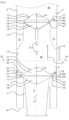
- FIG. 1 discloses schematically a longitudinal section of a scrubber according to a first embodiment of the invention.
- FIG. 2 discloses schematically a longitudinal section of a part of the scrubber in FIG. 1 .
- FIG. 3 discloses schematically a longitudinal section of an inner shield of the scrubber in FIG. 1 .
- FIG. 4 discloses schematically a transversal section along the line IV-IV in FIG. 2 .
- FIG. 5 discloses schematically a longitudinal section of the inner shield of a scrubber similar to FIG. 3 but according to a second embodiment.
- FIG. 6 discloses schematically a transversal section similar to the one in FIG. 4 , of an upstream deflector device according to a third embodiment.
- FIG. 1 discloses an inline scrubber 1 for cleaning of a gas, such as an exhaust gas from an engine, a burner a boiler, etc., for instance a marine vessel engine 2 schematically indicated in FIG. 1 .
- a gas such as an exhaust gas from an engine, a burner a boiler, etc.
- a marine vessel engine 2 schematically indicated in FIG. 1 .
- the scrubber 1 comprises a casing 3 , which extends along a longitudinal central axis x, and encloses a scrubbing chamber 4 .
- the longitudinal central axis x may be vertical as indicated in FIG. 1 .
- the scrubber 1 has a first end 1 a , that may form a lower end, and a second end 1 b , that may form an upper end.
- the scrubber 1 and the casing 3 have a circular cross-section, see FIG. 4 .
- the casing 3 comprises a gas inlet 5 for the gas to be cleaned, and a gas outlet 6 for the cleaned gas.
- the gas inlet 5 is provided at the first end 1 a and extends into the scrubbing chamber 4 .
- the gas outlet 6 is provided at the second end 1 b and extends out from the scrubbing chamber 4 .
- the gas inlet 5 and the gas outlet 6 are concentric with the longitudinal central axis x, see FIG. 1 .
- the casing 3 is configured to permit a gas flow of the gas to flow through the scrubbing chamber 4 in a flow direction F from the gas inlet 5 to the gas outlet 6 .
- the gas inlet 5 comprises an inlet tube 7 which is connected to an exhaust pipe 2 a of the marine vessel engine 2 .
- the inlet tube 7 extends into the scrubbing chamber 4 at the first end 1 a, see also FIG. 2 .
- the exhaust pipe 2 a and the inlet tube 7 may extend in line with the longitudinal central axis x.
- the scrubber 1 comprises at least one deflector device 11 , 12 provided in the scrubbing chamber 4 , concentrically with the casing 3 , between the gas inlet 5 and the gas outlet 6 .
- two deflector devices 11 , 12 are provided, one upstream deflector device 11 and one downstream deflector device 12 .
- the passage 28 between the deflector device 11 and the casing 3 has a varying width and the inner shield 20 extends through a most narrow portion of the passage 28 .
- the most narrow portion of the passage 28 is located at the downstream transversal plane Pb and/or at the upstream transversal plane Pa.
- the inner shield 20 is thus provided in the upstream scrubbing section 4 a at an axial level of the upstream deflector device 11 . More precisely, the outlet end 23 of the gap 21 is located axially closer to the gas inlet 5 than the upstream transversal plane Pa. Furthermore, the inlet end 22 of the gap 21 is located axially closer to the gas outlet 6 than the downstream transversal plane Pb.
- Scrubbing liquid collected on the downstream surface 17 of the upstream deflector device 11 may thus be retained on the downstream surface 17 by the edge member 33 .
- the edge member 33 comprises openings 35 extending from an inside to an outside of the edge member 33 and communicating with a respective one of the conveying members 30 .
- the openings 35 thus permit the scrubbing liquid collected on the downstream surface 17 to escape via the conveying members 30 , see FIG. 3 .
- FIG. 5 refers to a second embodiment that differs from the first embodiment in that the conveying members 30 are configured as pipes.
- At least one, for instance three, conveying members 30 may be provided from the downstream surface 17 of the downstream deflector device 12 to a position at the inner side 10 of the casing 3 .
- the end position 32 of these conveying members 30 may be adjacent to the inner side 10 of the casing 3 , where the velocity of the gas flow is lower than at a greater distance from the inner side 10 .
- no inner shield 20 is provided at the downstream deflector device 12 .
- a part of the droplets are forced towards the inner side 10 of the casing 3 . These droplets may then form a flow of liquid flowing towards the first liquid outlet 9 by means for the gravity force in a direction opposite to the flow direction F of the gas flow.
- the inner shield 20 locally shields the flow of liquid from the gas flow to prevent that the liquid is forced upwards by the gas flow as the liquid flows in the gap 21 outside the inner shield 20 . Thereby, draining of scrubbing liquid is facilitated.
- Another part of the droplets are flowing towards the downstream surface 17 of the upstream deflector device 11 in the middle of the upstream scrubbing section 4 a, where the velocity of the gas flow is lower than in a more outward area.
- the droplets hitting the downstream surface 17 of the upstream deflector device 11 form a liquid flowing on the downstream surface 17 towards the outer edge 17 ′ and the edge member 33 by means of the gravity force. From there, the liquid is conveyed via the conveying members 30 towards the inner side 10 of the casing 3 and in particular to the gap 21 . From the gap 21 , the liquid from the conveying members 30 is drained, by gravity, through the first liquid outlet 9 together with the liquid already flowing along the inner side 10 of the casing 3 .
- the flow area of the gas flow is reduced at the restriction element 13 resulting in an increase of the velocity of the gas flow when entering the downstream scrubbing section 4 b.
- the exhaust gas from the upstream scrubbing section 4 a is forced outwardly to the passage 28 between the downstream deflector device 12 and the inner side 10 of the casing 3 , where the decreased flow area results in a further increased velocity of the gas flow in the same way as at the upstream deflector device 11 .
- the scrubber 1 may comprise further spraying nozzles 8 , also below the upstream deflector device 11 , for example spraying nozzles for cooling the exhaust gas arranged outside the gas inlet 5 .
- the start position 31 and the end position 32 of the conveying members 30 need not be arranged as described above.
- the start position could be arranged on the downstream surface 17 of the upstream deflector device 11 at a distance from the outer edge 17 ′ and/or the conveying members 30 could extend through the upstream deflector device 11 .
- the downstream surface 17 could be plane.
- the start position 31 could even be arranged on the upstream surface 16 of the upstream deflector device 11 .
- the end position 32 could be arranged aligned with the start position 31 in relation to the longitudinal central axis (x).
Landscapes
- Chemical & Material Sciences (AREA)
- Chemical Kinetics & Catalysis (AREA)
- Engineering & Computer Science (AREA)
- Analytical Chemistry (AREA)
- Oil, Petroleum & Natural Gas (AREA)
- General Chemical & Material Sciences (AREA)
- Combustion & Propulsion (AREA)
- General Engineering & Computer Science (AREA)
- Mechanical Engineering (AREA)
- Treating Waste Gases (AREA)
- Gas Separation By Absorption (AREA)
- Exhaust Gas After Treatment (AREA)
- Separation Of Particles Using Liquids (AREA)
Abstract
Description
-
- a casing extending along a longitudinal central axis and enclosing a scrubbing chamber, wherein the casing has a gas inlet for the gas to be cleaned, which extends into the scrubbing chamber, and a gas outlet for the cleaned gas, which extends out from the scrubbing chamber, wherein the casing is configured to permit a gas flow of the gas to flow through the scrubbing chamber in a flow direction from the gas inlet to the gas outlet,
- a deflector device provided in the scrubbing chamber between the gas inlet and the gas outlet and forming a passage between the deflector device and the casing, and
- a spraying nozzle arranged between the gas outlet of the casing and the deflector device and configured to spray a scrubbing liquid into the scrubbing chamber and the gas flow.
Claims (18)
Applications Claiming Priority (4)
| Application Number | Priority Date | Filing Date | Title |
|---|---|---|---|
| EP17184158.8A EP3437717A1 (en) | 2017-08-01 | 2017-08-01 | A scrubber for cleaning of a gas |
| EP17184158.8 | 2017-08-01 | ||
| EP17184158 | 2017-08-01 | ||
| PCT/EP2018/066199 WO2019025071A1 (en) | 2017-08-01 | 2018-06-19 | A scrubber for cleaning of a gas |
Publications (2)
| Publication Number | Publication Date |
|---|---|
| US20200179863A1 US20200179863A1 (en) | 2020-06-11 |
| US12274970B2 true US12274970B2 (en) | 2025-04-15 |
Family
ID=59569144
Family Applications (1)
| Application Number | Title | Priority Date | Filing Date |
|---|---|---|---|
| US16/628,600 Active 2039-08-03 US12274970B2 (en) | 2017-08-01 | 2018-06-19 | Scrubber for cleaning of a gas |
Country Status (6)
| Country | Link |
|---|---|
| US (1) | US12274970B2 (en) |
| EP (2) | EP3437717A1 (en) |
| JP (1) | JP6912654B2 (en) |
| KR (1) | KR102320605B1 (en) |
| CN (1) | CN110913973B (en) |
| WO (1) | WO2019025071A1 (en) |
Families Citing this family (5)
| Publication number | Priority date | Publication date | Assignee | Title |
|---|---|---|---|---|
| EP3437718A1 (en) | 2017-08-01 | 2019-02-06 | Alfa Laval Corporate AB | A scrubber for cleaning of a gas |
| EP3437719A1 (en) | 2017-08-01 | 2019-02-06 | Alfa Laval Corporate AB | A scrubber for cleaning of a gas |
| EP3437717A1 (en) * | 2017-08-01 | 2019-02-06 | Alfa Laval Corporate AB | A scrubber for cleaning of a gas |
| DE102021121289A1 (en) * | 2021-08-17 | 2023-02-23 | Purem GmbH | Exhaust system for an internal combustion engine |
| CN117101310B (en) * | 2023-10-11 | 2025-09-02 | 金川集团镍钴股份有限公司 | A dynamic wave scrubber |
Citations (64)
| Publication number | Priority date | Publication date | Assignee | Title |
|---|---|---|---|---|
| FR624071A (en) | 1926-11-04 | 1927-07-07 | Cfcmug | Vertical scrubber for the treatment of gases or vapors |
| US1894744A (en) * | 1927-12-06 | 1933-01-17 | Centrifix Corp | Gas conditioner |
| US2114786A (en) * | 1935-08-30 | 1938-04-19 | Claude B Schneible | Column |
| US2143904A (en) * | 1937-02-27 | 1939-01-17 | Nat Aniline & Chem Co Inc | Reflux distributor for gas liquid contact apparatus |
| US2259033A (en) * | 1939-02-15 | 1941-10-14 | Ernest F Fisher | Liquid and air contact column for cleaning air and gases |
| US2409088A (en) * | 1943-07-09 | 1946-10-08 | Weits John | Device for washing and conditioning air and gases |
| US2428922A (en) * | 1944-09-30 | 1947-10-14 | Universal Oil Prod Co | Liquid distributing apparatus |
| US2587416A (en) * | 1949-02-08 | 1952-02-26 | Pangborn Corp | Dust collector |
| US2596104A (en) * | 1947-11-22 | 1952-05-13 | Claude B Schneible | Column apparatus |
| US2611685A (en) * | 1950-11-22 | 1952-09-23 | Standard Oil Dev Co | Fluid distributor for vessels |
| US2639947A (en) * | 1948-06-07 | 1953-05-26 | Ruhrchemie Ag | Liquid distributing tray |
| US2810450A (en) * | 1956-06-08 | 1957-10-22 | Allied Chem & Dye Corp | Method and apparatus for treating coke oven gas |
| US2972393A (en) * | 1959-03-25 | 1961-02-21 | Allied Chem | Process for treating coke oven gas |
| US3006623A (en) * | 1958-12-29 | 1961-10-31 | Exxon Research Engineering Co | Fluid distributor for packed columns |
| US3131237A (en) * | 1958-11-17 | 1964-04-28 | Jr Theron T Collins | Gas scrubbing apparatus |
| US3243171A (en) * | 1963-03-11 | 1966-03-29 | Us Stoneware Co | In-bed redistributor and method of assembly |
| US3290025A (en) * | 1965-11-19 | 1966-12-06 | Baltimore Aircoil Co Inc | Trough system for evaporative heat exchangers |
| US3327455A (en) * | 1966-07-08 | 1967-06-27 | Sidney B Wertheimer | Apparatus for controlling air pollution or the like |
| US3336733A (en) * | 1965-05-17 | 1967-08-22 | Cen Trific Air Products Inc | Gas scrubber |
| US3363843A (en) * | 1965-04-26 | 1968-01-16 | Union Oil Co | Fluid inlet distributor |
| US3408055A (en) * | 1965-04-20 | 1968-10-29 | Stamicarbon | Fluid distributor |
| US3456928A (en) * | 1967-05-24 | 1969-07-22 | Chemical Construction Corp | Combined blast furnace scrubber and dust catcher |
| US3497194A (en) * | 1966-09-24 | 1970-02-24 | Gottfried Bischoff Bau Komp Ga | Apparatus for the removal of dust from converter gases |
| US3708958A (en) * | 1971-07-19 | 1973-01-09 | C Duty | Device and method for removing pollutants from stack gases |
| US3779525A (en) * | 1971-08-19 | 1973-12-18 | Mitsui Shipbuilding Eng | Gas-liquid contacting apparatus |
| JPS5060874A (en) | 1973-10-02 | 1975-05-26 | ||
| JPS5065968A (en) | 1973-10-16 | 1975-06-03 | ||
| GB1509157A (en) | 1975-08-28 | 1978-04-26 | Metallgesellschaft Ag | Radial-flow gas scrubber |
| JPS53124383A (en) | 1977-04-04 | 1978-10-30 | Ren Tokigawa | Air purifier |
| US4231765A (en) * | 1979-04-17 | 1980-11-04 | Scott Morton J | Air cleaning apparatus and method |
| US4318717A (en) * | 1979-04-23 | 1982-03-09 | Rhone-Poulenc Industries | Method for the treatment of an impure gas stream and apparatus therefor |
| US4816191A (en) * | 1988-01-19 | 1989-03-28 | Koch Engineering Company, Inc. | Distributor for liquid-gas contact column and method of preparation and use |
| US5224351A (en) * | 1990-12-17 | 1993-07-06 | L'air Liquide, Societe Anonyme Pour L'etude Et L'exploitation Des Procedes Georges Claude | Air distillating column with cross-undulating lining |
| US5292353A (en) * | 1991-07-03 | 1994-03-08 | The Delfield Company | Air scrubber |
| US5648048A (en) | 1993-04-09 | 1997-07-15 | Babcock-Hitachi Kabushiki Kaisha | Wet-type flue gas desulfurization plant |
| DE10118961A1 (en) | 2001-04-10 | 2002-10-24 | Thermoselect Ag Vaduz | Dusty gas scrubber with overall zero or negative pressure loss, integrates jet pump operated by wash fluid to reduce pressure in gas stream |
| US20020158350A1 (en) * | 2001-04-10 | 2002-10-31 | Christoph Ender | Liquid distributor in mass transfer column and method of installation and use |
| US6550751B1 (en) * | 1997-11-26 | 2003-04-22 | Marsulex Environmental Technologies Corp. | Gas-liquid contactor with liquid redistribution device |
| WO2003045524A2 (en) | 2001-11-30 | 2003-06-05 | Diversified Metal Engineering Ltd. | Method and apparatus for scrubbing gases, using mixing vanes |
| US20060197239A1 (en) * | 2002-11-22 | 2006-09-07 | Henry Kister | Configurations and methods for ribbed downcomer wall |
| US20080290532A1 (en) | 2005-12-20 | 2008-11-27 | Shell Internationale Research Maatschappij B.V. | Fluid Inlet Device, Use, and Method or Retrofitting |
| CN101678295A (en) | 2007-05-18 | 2010-03-24 | 爱德华兹有限公司 | Apparatus for treating gas |
| EP2463014A1 (en) | 2010-12-10 | 2012-06-13 | Alstom Technology Ltd | A wet scrubber comprising deflector plates, and a method of cleaning a process gas |
| WO2012134470A1 (en) * | 2011-03-31 | 2012-10-04 | Air Products And Chemicals, Inc. | Shielding in a separation column |
| US20120280411A1 (en) * | 2009-12-23 | 2012-11-08 | Chemetics Inc. | Liquid Distribution Trough For Use In Towers in Sulphuric Acid And Carbon Capture Plants |
| DE102011122014A1 (en) * | 2011-12-22 | 2013-06-27 | Linde Aktiengesellschaft | Gas distribution arrangement for distributing acidic gas in cladding space of e.g. container, has impact element that is arranged at distribution aperture so that gas withdrawn from aperture is flowed against liquid moistening region |
| US20130269530A1 (en) * | 2010-09-16 | 2013-10-17 | Ccg Energy Technology Company Ltd. | Device and method for treating a hot gas flow containing slag |
| US20140166110A1 (en) * | 2012-12-14 | 2014-06-19 | Koch-Glitsch, Lp | Distributor in mass transfer column and method of use |
| WO2014128261A1 (en) | 2013-02-22 | 2014-08-28 | Marine Global Holding As | Marine exhaust gas scrubber |
| EP2775112B1 (en) | 2013-03-08 | 2015-10-07 | Alfa Laval Corporate AB | Cleaning system and method for reduction of SOx in exhaust gases |
| CN205127610U (en) | 2015-11-30 | 2016-04-06 | 梁成 | Novel dust removal desulfurization device |
| CN105597470A (en) | 2015-12-23 | 2016-05-25 | 天津赛智科技发展有限公司 | Paint mist purifying system |
| US20160206970A1 (en) * | 2013-09-25 | 2016-07-21 | Linde Aktiengesellschaft | Column with angular profiles |
| DE102015105283A1 (en) | 2015-02-18 | 2016-08-18 | Cft Gmbh Compact Filter Technic | High-performance wet scrubber with short housing |
| WO2016158571A1 (en) | 2015-03-31 | 2016-10-06 | 三菱重工業株式会社 | Demister unit and egr system |
| US20160332090A1 (en) * | 2013-12-20 | 2016-11-17 | Statoil Petroleum As | System for fluid redistribution |
| CN205730617U (en) | 2016-05-26 | 2016-11-30 | 江苏揽山环境科技股份有限公司 | Demister guide shell |
| CN106369650A (en) | 2016-08-26 | 2017-02-01 | 丁荣 | Oil fume purifier with waterproof fan |
| US20190344195A1 (en) * | 2018-05-08 | 2019-11-14 | Process Consulting Services, Inc | Coker fractionator spray wash chamber |
| US20200030712A1 (en) * | 2017-02-14 | 2020-01-30 | Covestro Deutschland Ag | Distributor device, in particular for falling film evaporators, and use thereof |
| US20200179863A1 (en) * | 2017-08-01 | 2020-06-11 | Alfa Laval Corporate Ab | A scrubber for cleaning of a gas |
| US20200206678A1 (en) * | 2017-08-01 | 2020-07-02 | Alfa Laval Corporate Ab | A scrubber for cleaning of a gas |
| US20200215477A1 (en) | 2017-08-01 | 2020-07-09 | Alfa Laval Corporate Ab | A scrubber for cleaning of a gas |
| US10981109B2 (en) * | 2017-05-11 | 2021-04-20 | General Electric Technology Gmbh | Wet scrubber tower with plates between nozzles for wet flue gas desulphurisation and particulate matter removal |
Family Cites Families (2)
| Publication number | Priority date | Publication date | Assignee | Title |
|---|---|---|---|---|
| US4722745A (en) * | 1987-04-13 | 1988-02-02 | Airpol, Inc. | Gas cleaning system for high top pressure blast furnaces |
| US7963282B2 (en) * | 2008-05-02 | 2011-06-21 | Captive-Aire Systems, Inc. | Kitchen hood assembly with a combination cleaning and fire suppression system |
-
2017
- 2017-08-01 EP EP17184158.8A patent/EP3437717A1/en not_active Withdrawn
-
2018
- 2018-06-19 US US16/628,600 patent/US12274970B2/en active Active
- 2018-06-19 CN CN201880050469.2A patent/CN110913973B/en active Active
- 2018-06-19 EP EP18732069.2A patent/EP3661627A1/en active Pending
- 2018-06-19 WO PCT/EP2018/066199 patent/WO2019025071A1/en not_active Ceased
- 2018-06-19 JP JP2020505251A patent/JP6912654B2/en active Active
- 2018-06-19 KR KR1020207005911A patent/KR102320605B1/en active Active
Patent Citations (73)
| Publication number | Priority date | Publication date | Assignee | Title |
|---|---|---|---|---|
| FR624071A (en) | 1926-11-04 | 1927-07-07 | Cfcmug | Vertical scrubber for the treatment of gases or vapors |
| US1894744A (en) * | 1927-12-06 | 1933-01-17 | Centrifix Corp | Gas conditioner |
| US2114786A (en) * | 1935-08-30 | 1938-04-19 | Claude B Schneible | Column |
| US2143904A (en) * | 1937-02-27 | 1939-01-17 | Nat Aniline & Chem Co Inc | Reflux distributor for gas liquid contact apparatus |
| US2259033A (en) * | 1939-02-15 | 1941-10-14 | Ernest F Fisher | Liquid and air contact column for cleaning air and gases |
| US2409088A (en) * | 1943-07-09 | 1946-10-08 | Weits John | Device for washing and conditioning air and gases |
| US2428922A (en) * | 1944-09-30 | 1947-10-14 | Universal Oil Prod Co | Liquid distributing apparatus |
| US2596104A (en) * | 1947-11-22 | 1952-05-13 | Claude B Schneible | Column apparatus |
| US2639947A (en) * | 1948-06-07 | 1953-05-26 | Ruhrchemie Ag | Liquid distributing tray |
| US2587416A (en) * | 1949-02-08 | 1952-02-26 | Pangborn Corp | Dust collector |
| US2611685A (en) * | 1950-11-22 | 1952-09-23 | Standard Oil Dev Co | Fluid distributor for vessels |
| US2810450A (en) * | 1956-06-08 | 1957-10-22 | Allied Chem & Dye Corp | Method and apparatus for treating coke oven gas |
| US3131237A (en) * | 1958-11-17 | 1964-04-28 | Jr Theron T Collins | Gas scrubbing apparatus |
| US3006623A (en) * | 1958-12-29 | 1961-10-31 | Exxon Research Engineering Co | Fluid distributor for packed columns |
| US2972393A (en) * | 1959-03-25 | 1961-02-21 | Allied Chem | Process for treating coke oven gas |
| US3243171A (en) * | 1963-03-11 | 1966-03-29 | Us Stoneware Co | In-bed redistributor and method of assembly |
| US3408055A (en) * | 1965-04-20 | 1968-10-29 | Stamicarbon | Fluid distributor |
| US3363843A (en) * | 1965-04-26 | 1968-01-16 | Union Oil Co | Fluid inlet distributor |
| US3336733A (en) * | 1965-05-17 | 1967-08-22 | Cen Trific Air Products Inc | Gas scrubber |
| US3290025A (en) * | 1965-11-19 | 1966-12-06 | Baltimore Aircoil Co Inc | Trough system for evaporative heat exchangers |
| US3327455A (en) * | 1966-07-08 | 1967-06-27 | Sidney B Wertheimer | Apparatus for controlling air pollution or the like |
| US3497194A (en) * | 1966-09-24 | 1970-02-24 | Gottfried Bischoff Bau Komp Ga | Apparatus for the removal of dust from converter gases |
| US3456928A (en) * | 1967-05-24 | 1969-07-22 | Chemical Construction Corp | Combined blast furnace scrubber and dust catcher |
| US3708958A (en) * | 1971-07-19 | 1973-01-09 | C Duty | Device and method for removing pollutants from stack gases |
| US3779525A (en) * | 1971-08-19 | 1973-12-18 | Mitsui Shipbuilding Eng | Gas-liquid contacting apparatus |
| JPS5060874A (en) | 1973-10-02 | 1975-05-26 | ||
| JPS5065968A (en) | 1973-10-16 | 1975-06-03 | ||
| GB1509157A (en) | 1975-08-28 | 1978-04-26 | Metallgesellschaft Ag | Radial-flow gas scrubber |
| JPS53124383A (en) | 1977-04-04 | 1978-10-30 | Ren Tokigawa | Air purifier |
| US4231765A (en) * | 1979-04-17 | 1980-11-04 | Scott Morton J | Air cleaning apparatus and method |
| US4318717A (en) * | 1979-04-23 | 1982-03-09 | Rhone-Poulenc Industries | Method for the treatment of an impure gas stream and apparatus therefor |
| US4816191A (en) * | 1988-01-19 | 1989-03-28 | Koch Engineering Company, Inc. | Distributor for liquid-gas contact column and method of preparation and use |
| US5224351A (en) * | 1990-12-17 | 1993-07-06 | L'air Liquide, Societe Anonyme Pour L'etude Et L'exploitation Des Procedes Georges Claude | Air distillating column with cross-undulating lining |
| US5292353A (en) * | 1991-07-03 | 1994-03-08 | The Delfield Company | Air scrubber |
| US5648048A (en) | 1993-04-09 | 1997-07-15 | Babcock-Hitachi Kabushiki Kaisha | Wet-type flue gas desulfurization plant |
| US6550751B1 (en) * | 1997-11-26 | 2003-04-22 | Marsulex Environmental Technologies Corp. | Gas-liquid contactor with liquid redistribution device |
| DE10118961A1 (en) | 2001-04-10 | 2002-10-24 | Thermoselect Ag Vaduz | Dusty gas scrubber with overall zero or negative pressure loss, integrates jet pump operated by wash fluid to reduce pressure in gas stream |
| US20020158350A1 (en) * | 2001-04-10 | 2002-10-31 | Christoph Ender | Liquid distributor in mass transfer column and method of installation and use |
| US20040194622A1 (en) | 2001-04-10 | 2004-10-07 | Kiss Gunter H. | Washer and method for purifying gases |
| WO2003045524A2 (en) | 2001-11-30 | 2003-06-05 | Diversified Metal Engineering Ltd. | Method and apparatus for scrubbing gases, using mixing vanes |
| EP1448291A2 (en) | 2001-11-30 | 2004-08-25 | Diversified Metal Engineering Ltd. | Method and apparatus for scrubbing gases, using mixing vanes |
| US20040255779A1 (en) * | 2001-11-30 | 2004-12-23 | Andrew Trivett | Method and apparatus for scrubbing gases, using mixing vanes |
| JP2005510649A (en) | 2001-11-30 | 2005-04-21 | ディヴァシファイド メタル エンジニアリング エルティーディー. | Method and apparatus for cleaning gas using mixing blades |
| US20060197239A1 (en) * | 2002-11-22 | 2006-09-07 | Henry Kister | Configurations and methods for ribbed downcomer wall |
| US20080290532A1 (en) | 2005-12-20 | 2008-11-27 | Shell Internationale Research Maatschappij B.V. | Fluid Inlet Device, Use, and Method or Retrofitting |
| CN101678295A (en) | 2007-05-18 | 2010-03-24 | 爱德华兹有限公司 | Apparatus for treating gas |
| US20100303676A1 (en) | 2007-05-18 | 2010-12-02 | Andrew James Seeley | Apparatus for treating gas |
| US20120280411A1 (en) * | 2009-12-23 | 2012-11-08 | Chemetics Inc. | Liquid Distribution Trough For Use In Towers in Sulphuric Acid And Carbon Capture Plants |
| US20130269530A1 (en) * | 2010-09-16 | 2013-10-17 | Ccg Energy Technology Company Ltd. | Device and method for treating a hot gas flow containing slag |
| EP2463014A1 (en) | 2010-12-10 | 2012-06-13 | Alstom Technology Ltd | A wet scrubber comprising deflector plates, and a method of cleaning a process gas |
| WO2012134470A1 (en) * | 2011-03-31 | 2012-10-04 | Air Products And Chemicals, Inc. | Shielding in a separation column |
| DE102011122014A1 (en) * | 2011-12-22 | 2013-06-27 | Linde Aktiengesellschaft | Gas distribution arrangement for distributing acidic gas in cladding space of e.g. container, has impact element that is arranged at distribution aperture so that gas withdrawn from aperture is flowed against liquid moistening region |
| US20140166110A1 (en) * | 2012-12-14 | 2014-06-19 | Koch-Glitsch, Lp | Distributor in mass transfer column and method of use |
| US20160016109A1 (en) * | 2013-02-22 | 2016-01-21 | Marine Global Holding As | Marine exhaust gas scrubber |
| US9776125B2 (en) * | 2013-02-22 | 2017-10-03 | Yara Marine Technologies As | Marine exhaust gas scrubber |
| WO2014128261A1 (en) | 2013-02-22 | 2014-08-28 | Marine Global Holding As | Marine exhaust gas scrubber |
| JP2016514038A (en) | 2013-02-22 | 2016-05-19 | マリン グローバル ホールディング エーエスMarine Global Holding As | Scrubber for exhaust gas from ships |
| EP2775112B1 (en) | 2013-03-08 | 2015-10-07 | Alfa Laval Corporate AB | Cleaning system and method for reduction of SOx in exhaust gases |
| US20160206970A1 (en) * | 2013-09-25 | 2016-07-21 | Linde Aktiengesellschaft | Column with angular profiles |
| US20160332090A1 (en) * | 2013-12-20 | 2016-11-17 | Statoil Petroleum As | System for fluid redistribution |
| DE102015105283A1 (en) | 2015-02-18 | 2016-08-18 | Cft Gmbh Compact Filter Technic | High-performance wet scrubber with short housing |
| WO2016158571A1 (en) | 2015-03-31 | 2016-10-06 | 三菱重工業株式会社 | Demister unit and egr system |
| CN205127610U (en) | 2015-11-30 | 2016-04-06 | 梁成 | Novel dust removal desulfurization device |
| CN105597470A (en) | 2015-12-23 | 2016-05-25 | 天津赛智科技发展有限公司 | Paint mist purifying system |
| CN205730617U (en) | 2016-05-26 | 2016-11-30 | 江苏揽山环境科技股份有限公司 | Demister guide shell |
| CN106369650A (en) | 2016-08-26 | 2017-02-01 | 丁荣 | Oil fume purifier with waterproof fan |
| US20200030712A1 (en) * | 2017-02-14 | 2020-01-30 | Covestro Deutschland Ag | Distributor device, in particular for falling film evaporators, and use thereof |
| US10981109B2 (en) * | 2017-05-11 | 2021-04-20 | General Electric Technology Gmbh | Wet scrubber tower with plates between nozzles for wet flue gas desulphurisation and particulate matter removal |
| US20200179863A1 (en) * | 2017-08-01 | 2020-06-11 | Alfa Laval Corporate Ab | A scrubber for cleaning of a gas |
| US20200206678A1 (en) * | 2017-08-01 | 2020-07-02 | Alfa Laval Corporate Ab | A scrubber for cleaning of a gas |
| US20200215477A1 (en) | 2017-08-01 | 2020-07-09 | Alfa Laval Corporate Ab | A scrubber for cleaning of a gas |
| US11141690B2 (en) * | 2017-08-01 | 2021-10-12 | Alfa Laval Corporate Ab | Scrubber for cleaning of a gas |
| US20190344195A1 (en) * | 2018-05-08 | 2019-11-14 | Process Consulting Services, Inc | Coker fractionator spray wash chamber |
Non-Patent Citations (6)
| Title |
|---|
| An English Translation of the Office Action (Notice of Reasons for Rejection) issued on Feb. 1, 2021, by the Japanese Patent Office in corresponding Japanese Patent Application No. 2020-505251. (5 pages). |
| European Search Report and European Search Opinion issued by the European Patent Office on Jan. 8, 2018 in counterpart European Patent Application No. 17184158.8 (5 pages). |
| International Search Report (PCT/ISA/210) mailed on Sep. 25, 2018, by the European Patent Office as the International Searching Authority for International Application No. PCT/EP2018/066199. |
| Office Action (Second Office Action) issued Feb. 14, 2022, by the State Intellectual Property Office of People's Republic of China in corresponding Chinese Patent Application No. 201880050196.1 and an English Translation of the Office Action. (11 pages). |
| Office Action issued Jul. 27, 2021, by State Intellectual Property Office of People's Republic of China in corresponding Chinese Patent Application No. 201880050469.2. (11 pages). |
| Written Opinion (PCT/ISA/237) mailed on Sep. 25, 2018, by the European Patent Office as the International Searching Authority for International Application No. PCT/EP2018/066199. |
Also Published As
| Publication number | Publication date |
|---|---|
| EP3437717A1 (en) | 2019-02-06 |
| KR102320605B1 (en) | 2021-11-04 |
| KR20200037324A (en) | 2020-04-08 |
| JP6912654B2 (en) | 2021-08-04 |
| WO2019025071A1 (en) | 2019-02-07 |
| CN110913973B (en) | 2022-03-11 |
| JP2020529308A (en) | 2020-10-08 |
| CN110913973A (en) | 2020-03-24 |
| EP3661627A1 (en) | 2020-06-10 |
| US20200179863A1 (en) | 2020-06-11 |
Similar Documents
| Publication | Publication Date | Title |
|---|---|---|
| US11141691B2 (en) | Scrubber for cleaning of a gas | |
| US12274970B2 (en) | Scrubber for cleaning of a gas | |
| US11141690B2 (en) | Scrubber for cleaning of a gas | |
| JP6336478B2 (en) | Cyclone, cyclone mist removing device and method of use | |
| US20100325956A1 (en) | Cooling chamber assembly for a gasifier | |
| CN102559280A (en) | Gasification quench chamber baffle | |
| KR20060128883A (en) | Apparatus and method for more evenly and easily distributing steam in a column for mass transfer and heat exchange | |
| DK2539047T3 (en) | PIPES AND DEVICES TO COLLECT A EDGE FILM CONDENSATE AND DRAINAGE FOR BUILT IN THERE | |
| US2782772A (en) | Vapor generator and liquid flow means therefor | |
| EP4146375B1 (en) | Wet inline scrubber with a side inlet for reducing the amount of sox in an exhaust gas produced by one or more engines of a marine vessel | |
| HK40082379B (en) | Wet inline scrubber with a side inlet for reducing the amount of sox in an exhaust gas produced by one or more engines of a marine vessel | |
| HK40082379A (en) | Wet inline scrubber with a side inlet for reducing the amount of sox in an exhaust gas produced by one or more engines of a marine vessel | |
| RU2688761C1 (en) | Foam mass exchange apparatus | |
| CN115430290A (en) | Flue gas washing system | |
| KR20120059422A (en) | Gasification quench chamber baffle | |
| RU99115720A (en) | GAS CLEANING DEVICE | |
| KR930702086A (en) | Gas flow cleaning method and apparatus |
Legal Events
| Date | Code | Title | Description |
|---|---|---|---|
| AS | Assignment |
Owner name: ALFA LAVAL CORPORATE AB, SWEDEN Free format text: ASSIGNMENT OF ASSIGNORS INTEREST;ASSIGNOR:KRUSE MORTENSEN, RUDDI;REEL/FRAME:051413/0377 Effective date: 20180628 |
|
| FEPP | Fee payment procedure |
Free format text: ENTITY STATUS SET TO UNDISCOUNTED (ORIGINAL EVENT CODE: BIG.); ENTITY STATUS OF PATENT OWNER: LARGE ENTITY |
|
| STPP | Information on status: patent application and granting procedure in general |
Free format text: DOCKETED NEW CASE - READY FOR EXAMINATION |
|
| STPP | Information on status: patent application and granting procedure in general |
Free format text: NON FINAL ACTION MAILED |
|
| STPP | Information on status: patent application and granting procedure in general |
Free format text: RESPONSE TO NON-FINAL OFFICE ACTION ENTERED AND FORWARDED TO EXAMINER |
|
| STPP | Information on status: patent application and granting procedure in general |
Free format text: FINAL REJECTION MAILED |
|
| STPP | Information on status: patent application and granting procedure in general |
Free format text: RESPONSE AFTER FINAL ACTION FORWARDED TO EXAMINER |
|
| STPP | Information on status: patent application and granting procedure in general |
Free format text: ADVISORY ACTION MAILED |
|
| STPP | Information on status: patent application and granting procedure in general |
Free format text: DOCKETED NEW CASE - READY FOR EXAMINATION |
|
| STPP | Information on status: patent application and granting procedure in general |
Free format text: NON FINAL ACTION MAILED |
|
| STPP | Information on status: patent application and granting procedure in general |
Free format text: RESPONSE TO NON-FINAL OFFICE ACTION ENTERED AND FORWARDED TO EXAMINER |
|
| STPP | Information on status: patent application and granting procedure in general |
Free format text: FINAL REJECTION MAILED |
|
| STPP | Information on status: patent application and granting procedure in general |
Free format text: RESPONSE AFTER FINAL ACTION FORWARDED TO EXAMINER |
|
| STPP | Information on status: patent application and granting procedure in general |
Free format text: NON FINAL ACTION MAILED |
|
| STPP | Information on status: patent application and granting procedure in general |
Free format text: RESPONSE TO NON-FINAL OFFICE ACTION ENTERED AND FORWARDED TO EXAMINER |
|
| STPP | Information on status: patent application and granting procedure in general |
Free format text: EX PARTE QUAYLE ACTION MAILED |
|
| STPP | Information on status: patent application and granting procedure in general |
Free format text: RESPONSE TO EX PARTE QUAYLE ACTION ENTERED AND FORWARDED TO EXAMINER |
|
| STPP | Information on status: patent application and granting procedure in general |
Free format text: NOTICE OF ALLOWANCE MAILED -- APPLICATION RECEIVED IN OFFICE OF PUBLICATIONS |
|
| STPP | Information on status: patent application and granting procedure in general |
Free format text: NOTICE OF ALLOWANCE MAILED -- APPLICATION RECEIVED IN OFFICE OF PUBLICATIONS |
|
| STCF | Information on status: patent grant |
Free format text: PATENTED CASE |