US12259593B2 - Lens barrel and image pickup apparatus - Google Patents
Lens barrel and image pickup apparatus Download PDFInfo
- Publication number
- US12259593B2 US12259593B2 US18/317,256 US202318317256A US12259593B2 US 12259593 B2 US12259593 B2 US 12259593B2 US 202318317256 A US202318317256 A US 202318317256A US 12259593 B2 US12259593 B2 US 12259593B2
- Authority
- US
- United States
- Prior art keywords
- lens barrel
- moving unit
- imaging
- sliding surface
- optical axis
- Prior art date
- Legal status (The legal status is an assumption and is not a legal conclusion. Google has not performed a legal analysis and makes no representation as to the accuracy of the status listed.)
- Active, expires
Links
- 230000003287 optical effect Effects 0.000 claims abstract description 109
- 238000003384 imaging method Methods 0.000 claims abstract description 97
- 230000007704 transition Effects 0.000 claims abstract description 17
- 230000000087 stabilizing effect Effects 0.000 claims description 28
- 230000007246 mechanism Effects 0.000 description 21
- 230000006870 function Effects 0.000 description 8
- 238000006243 chemical reaction Methods 0.000 description 4
- 230000004044 response Effects 0.000 description 3
- 230000006641 stabilisation Effects 0.000 description 3
- 238000011105 stabilization Methods 0.000 description 3
- 238000004364 calculation method Methods 0.000 description 2
- 230000008859 change Effects 0.000 description 2
- 230000006835 compression Effects 0.000 description 2
- 238000007906 compression Methods 0.000 description 2
- 238000004590 computer program Methods 0.000 description 2
- 238000010586 diagram Methods 0.000 description 2
- 238000002360 preparation method Methods 0.000 description 2
- 230000001133 acceleration Effects 0.000 description 1
- 238000013459 approach Methods 0.000 description 1
- 230000008901 benefit Effects 0.000 description 1
- 230000007423 decrease Effects 0.000 description 1
- 238000001514 detection method Methods 0.000 description 1
- 238000006073 displacement reaction Methods 0.000 description 1
- 230000005389 magnetism Effects 0.000 description 1
- 238000012986 modification Methods 0.000 description 1
- 230000004048 modification Effects 0.000 description 1
- 238000005375 photometry Methods 0.000 description 1
- 230000002265 prevention Effects 0.000 description 1
Images


Classifications
-
- G—PHYSICS
- G02—OPTICS
- G02B—OPTICAL ELEMENTS, SYSTEMS OR APPARATUS
- G02B7/00—Mountings, adjusting means, or light-tight connections, for optical elements
- G02B7/02—Mountings, adjusting means, or light-tight connections, for optical elements for lenses
- G02B7/021—Mountings, adjusting means, or light-tight connections, for optical elements for lenses for more than one lens
-
- G—PHYSICS
- G02—OPTICS
- G02B—OPTICAL ELEMENTS, SYSTEMS OR APPARATUS
- G02B27/00—Optical systems or apparatus not provided for by any of the groups G02B1/00 - G02B26/00, G02B30/00
- G02B27/64—Imaging systems using optical elements for stabilisation of the lateral and angular position of the image
- G02B27/646—Imaging systems using optical elements for stabilisation of the lateral and angular position of the image compensating for small deviations, e.g. due to vibration or shake
-
- G—PHYSICS
- G02—OPTICS
- G02B—OPTICAL ELEMENTS, SYSTEMS OR APPARATUS
- G02B7/00—Mountings, adjusting means, or light-tight connections, for optical elements
- G02B7/02—Mountings, adjusting means, or light-tight connections, for optical elements for lenses
- G02B7/04—Mountings, adjusting means, or light-tight connections, for optical elements for lenses with mechanism for focusing or varying magnification
- G02B7/10—Mountings, adjusting means, or light-tight connections, for optical elements for lenses with mechanism for focusing or varying magnification by relative axial movement of several lenses, e.g. of varifocal objective lens
- G02B7/102—Mountings, adjusting means, or light-tight connections, for optical elements for lenses with mechanism for focusing or varying magnification by relative axial movement of several lenses, e.g. of varifocal objective lens controlled by a microcomputer
-
- G—PHYSICS
- G03—PHOTOGRAPHY; CINEMATOGRAPHY; ANALOGOUS TECHNIQUES USING WAVES OTHER THAN OPTICAL WAVES; ELECTROGRAPHY; HOLOGRAPHY
- G03B—APPARATUS OR ARRANGEMENTS FOR TAKING PHOTOGRAPHS OR FOR PROJECTING OR VIEWING THEM; APPARATUS OR ARRANGEMENTS EMPLOYING ANALOGOUS TECHNIQUES USING WAVES OTHER THAN OPTICAL WAVES; ACCESSORIES THEREFOR
- G03B17/00—Details of cameras or camera bodies; Accessories therefor
- G03B17/02—Bodies
- G03B17/04—Bodies collapsible, foldable or extensible, e.g. book type
-
- G—PHYSICS
- G03—PHOTOGRAPHY; CINEMATOGRAPHY; ANALOGOUS TECHNIQUES USING WAVES OTHER THAN OPTICAL WAVES; ELECTROGRAPHY; HOLOGRAPHY
- G03B—APPARATUS OR ARRANGEMENTS FOR TAKING PHOTOGRAPHS OR FOR PROJECTING OR VIEWING THEM; APPARATUS OR ARRANGEMENTS EMPLOYING ANALOGOUS TECHNIQUES USING WAVES OTHER THAN OPTICAL WAVES; ACCESSORIES THEREFOR
- G03B5/00—Adjustment of optical system relative to image or object surface other than for focusing
-
- H—ELECTRICITY
- H04—ELECTRIC COMMUNICATION TECHNIQUE
- H04N—PICTORIAL COMMUNICATION, e.g. TELEVISION
- H04N23/00—Cameras or camera modules comprising electronic image sensors; Control thereof
- H04N23/50—Constructional details
- H04N23/54—Mounting of pick-up tubes, electronic image sensors, deviation or focusing coils
-
- H—ELECTRICITY
- H04—ELECTRIC COMMUNICATION TECHNIQUE
- H04N—PICTORIAL COMMUNICATION, e.g. TELEVISION
- H04N23/00—Cameras or camera modules comprising electronic image sensors; Control thereof
- H04N23/50—Constructional details
- H04N23/55—Optical parts specially adapted for electronic image sensors; Mounting thereof
-
- H—ELECTRICITY
- H04—ELECTRIC COMMUNICATION TECHNIQUE
- H04N—PICTORIAL COMMUNICATION, e.g. TELEVISION
- H04N23/00—Cameras or camera modules comprising electronic image sensors; Control thereof
- H04N23/60—Control of cameras or camera modules
- H04N23/68—Control of cameras or camera modules for stable pick-up of the scene, e.g. compensating for camera body vibrations
- H04N23/681—Motion detection
- H04N23/6812—Motion detection based on additional sensors, e.g. acceleration sensors
-
- H—ELECTRICITY
- H04—ELECTRIC COMMUNICATION TECHNIQUE
- H04N—PICTORIAL COMMUNICATION, e.g. TELEVISION
- H04N23/00—Cameras or camera modules comprising electronic image sensors; Control thereof
- H04N23/60—Control of cameras or camera modules
- H04N23/68—Control of cameras or camera modules for stable pick-up of the scene, e.g. compensating for camera body vibrations
- H04N23/682—Vibration or motion blur correction
- H04N23/685—Vibration or motion blur correction performed by mechanical compensation
- H04N23/687—Vibration or motion blur correction performed by mechanical compensation by shifting the lens or sensor position
-
- H—ELECTRICITY
- H04—ELECTRIC COMMUNICATION TECHNIQUE
- H04N—PICTORIAL COMMUNICATION, e.g. TELEVISION
- H04N23/00—Cameras or camera modules comprising electronic image sensors; Control thereof
- H04N23/60—Control of cameras or camera modules
- H04N23/69—Control of means for changing angle of the field of view, e.g. optical zoom objectives or electronic zooming
-
- G—PHYSICS
- G02—OPTICS
- G02B—OPTICAL ELEMENTS, SYSTEMS OR APPARATUS
- G02B7/00—Mountings, adjusting means, or light-tight connections, for optical elements
- G02B7/28—Systems for automatic generation of focusing signals
-
- G—PHYSICS
- G03—PHOTOGRAPHY; CINEMATOGRAPHY; ANALOGOUS TECHNIQUES USING WAVES OTHER THAN OPTICAL WAVES; ELECTROGRAPHY; HOLOGRAPHY
- G03B—APPARATUS OR ARRANGEMENTS FOR TAKING PHOTOGRAPHS OR FOR PROJECTING OR VIEWING THEM; APPARATUS OR ARRANGEMENTS EMPLOYING ANALOGOUS TECHNIQUES USING WAVES OTHER THAN OPTICAL WAVES; ACCESSORIES THEREFOR
- G03B2205/00—Adjustment of optical system relative to image or object surface other than for focusing
- G03B2205/0007—Movement of one or more optical elements for control of motion blur
- G03B2205/0015—Movement of one or more optical elements for control of motion blur by displacing one or more optical elements normal to the optical axis
-
- G—PHYSICS
- G03—PHOTOGRAPHY; CINEMATOGRAPHY; ANALOGOUS TECHNIQUES USING WAVES OTHER THAN OPTICAL WAVES; ELECTROGRAPHY; HOLOGRAPHY
- G03B—APPARATUS OR ARRANGEMENTS FOR TAKING PHOTOGRAPHS OR FOR PROJECTING OR VIEWING THEM; APPARATUS OR ARRANGEMENTS EMPLOYING ANALOGOUS TECHNIQUES USING WAVES OTHER THAN OPTICAL WAVES; ACCESSORIES THEREFOR
- G03B2205/00—Adjustment of optical system relative to image or object surface other than for focusing
- G03B2205/0046—Movement of one or more optical elements for zooming
Definitions
- FIGS. 1 A and 1 B are perspective views of an image pickup apparatus that includes a lens barrel according to one embodiment of the disclosure.
- FIGS. 5 A and 5 B are front views of an image stabilizing apparatus.
- FIG. 6 is a developed view illustrating cam loci of cam grooves formed in a cam cylinder.
- FIG. 9 is a sectional view taken along a line B-B in FIG. 7 .
- FIG. 11 illustrates a rotational operation torque by a shift lever (withdrawal lever).
- FIGS. 1 A and 1 B are perspective views of an image pickup apparatus that includes a lens barrel according to one embodiment of the disclosure.
- FIGS. 1 A and 1 B are perspective views viewed from a front side (object side) and a rear side (image plane side), respectively.
- the image pickup apparatus includes a lens barrel 101 and a camera body 1 to which the lens barrel 101 is detachably attached.
- an X-axis direction is an optical axis direction, which is a direction in which the optical axis of the imaging optical system of the lens barrel 101 extends (a direction along the optical axis).
- a Z-axis direction (horizontal direction) and a Y-axis direction (vertical direction) are directions orthogonal to the X-axis direction.
- the Z-axis direction and the Y-axis direction are collectively referred to as a Z/Y-axis direction.
- a rotating direction about the Z-axis is defined as a pitch direction
- a rotating direction about the Y-axis is defined as a yaw direction.
- the pitch direction and yaw direction (collectively referred to as a pitch/yaw direction hereinafter) are rotating directions about two axes, the Z-axis and the Y-axis, which are orthogonal to each other.
- the lens barrel 101 and the camera body 1 are separate components, but they may be integrated with each other.
- a grip portion 2 for the user to grip the camera body 1 by hand is provided on the left side of the camera body 1 viewed from the front side (right side viewed from the back side).
- a power operation unit 3 is disposed on a top surface of the camera body 1 .
- the user turns on the power operation unit 3 of the camera body 1 in the power off state, the power supply starts and the camera body 1 is powered on, and a computer program such as origin detecting processing of the focus unit is executed, the camera becomes in an imaging standby state.
- the lens barrel 101 is mechanically and electrically connected to the camera body 1 while the camera body 1 is powered off, energization from the camera body 1 to the lens barrel 101 is started and the origin detecting processing of the focus unit is performed.
- the user turns off the power operation unit 3 while the camera body 1 is powered on, the camera body 1 becomes powered off.
- a mode dial 4 , a release button 5 , and an accessory shoe 6 are provided on the top surface of the camera body 1 .
- An imaging mode can be switched by the user rotating the mode dial 4 .
- the imaging mode includes a manual still image imaging mode in which the user can arbitrarily set an imaging condition such as a shutter speed and an F-number (aperture value), an automatic still image capturing mode in which a proper exposure amount is automatically obtained, and a moving image capturing mode.
- Half-pressing the release button 5 the user can instruct an imaging preparation operation such as autofocus (AF) and auto-exposure (AE) control, and fully pressing the release button 5 , the user can instruct imaging.
- An accessory (camera accessory) such as an external flash or lighting unit is detachably attached to the accessory shoe 6 .
- the lens barrel 101 includes a lens mount 102 that can be mechanically and electrically connected to a camera mount 7 provided on the camera body 1 , and an imaging optical system that forms an object image.
- a zoom operation ring (operation member) 103 is provided on the outer circumference of the lens barrel 101 and is rotatable about the optical axis by user operation.
- a zoom unit that constitutes the imaging optical system moves to a position corresponding to an angle of the zoom operation ring 103 in a range from a wide-angle end to a telephoto end. Thereby, the user can capture an image at a desired angle of view.
- the lens barrel 101 is in an imaging state in which imaging is enabled.
- the zoom operation ring 103 is further operated after the zoom unit reaches the wide-angle end from the telephoto end, the zoom unit reaches a retraction end where imaging is restricted.
- the lens barrel 101 is in a retracted state (non-imaging state) in which the imaging optical system is housed and the overall length in the optical axis direction becomes the shortest length.
- imaging is restricted means that part of the function of the image pickup apparatus does not normally operate.
- the lens barrel in the retracted state can image an object, but a captured image may be out of focus and at least partially blurred.
- a rear operation unit 8 and a display unit 9 are provided on the rear surface of the camera body 1 .
- the rear operation unit 8 includes a plurality of buttons and a dial to which various functions are assigned.
- the display unit 9 displays a live-view (through) image of an object image captured by an image sensor, which will be described below.
- the display unit 9 also displays an imaging parameter indicating an imaging condition such as a shutter speed and an F-number. At this time, the user can change a set value of the imaging parameter by operating the rear operation unit 8 while viewing the display on the display unit 9 .
- the rear operation unit 8 includes a playback button for instructing playback of a recorded captured image. In a case where the user operates the playback button, the captured image is played back and displayed on the display unit 9 .
- the display unit 9 may be of a touch panel type and configured to have the same function as the rear operation unit 8 .
- FIG. 2 is a block diagram illustrating an electrical and optical configuration of the image pickup apparatus.
- the camera body 1 includes a power supply unit 10 that supplies power to the camera body 1 and the lens barrel 101 , the power operation unit 3 , the mode dial 4 , the release button 5 , the rear operation unit 8 , and an operation unit 11 including a touch panel function of the display unit 9 .
- the camera body 1 further includes a camera control unit 12 , a shutter unit 14 , a shutter driving unit 15 , an image sensor 16 , an image processing unit 17 , and a focus detector 18 .
- the overall control of the image pickup apparatus is performed by the camera control unit 12 and a lens control unit 104 provided in the lens barrel 101 cooperating with each other.
- the camera control unit 12 reads and executes a computer program stored in a memory 13 . At this time, the camera control unit 12 communicates various control signals, data, etc. with the lens control unit 104 via the communication terminal of an electrical contact 105 provided on the lens mount 102 .
- the electrical contact 105 includes a power terminal for supplying power from the power supply unit 10 to the lens barrel 101 .
- the shutter unit 14 controls an exposure amount to the image sensor 16 .
- the image sensor 16 photoelectrically converts an object image formed by the imaging optical system and outputs an imaging signal.
- the image processing unit 17 generates an image signal after performing various image processing for the imaging signal.
- the display unit 9 displays an image signal (live-view image) output from the image processing unit 17 , displays an imaging parameter, and plays back and displays captured images recorded in the memory 13 or an unillustrated recording medium.
- the imaging optical system in the lens barrel 101 includes a zoom unit 110 connected to a zoom operation ring 103 and movable along the optical axis to change an angle of view, and an image stabilizing unit (image blur correcting unit) 112 that includes a shift lens (first optical member) 601 , which will be described below.
- the image stabilizing unit 112 reduces image blur by moving (shifting) in the Z/Y-axis directions orthogonal to the optical axis.
- the imaging optical system further includes an aperture (stop) (diaphragm) unit 301 that performs a light amount adjusting operation, and a focus unit 114 that includes a focus lens that moves in the optical axis direction during focusing.
- the lens barrel 101 includes an image stabilizing driving unit 201 that moves the image stabilizing unit 112 , an aperture driving unit 302 that moves the aperture unit 301 , and a focus driving unit 401 that moves the focus unit 114 .
- the camera control unit 12 controls the focus driving unit 401 in response to an imaging preparation operation performed for the operation unit 11 (such as half-pressing operation of the release button 5 ). For example, in a case where an AF operation is instructed, the focus detector 18 determines a focus state of an object image on the imaging plane of the image sensor 16 based on an image signal generated by the image processing unit 17 , generates a focus signal, and transmits it to the camera control unit 12 .
- the focus driving unit 401 also transmits information about the current position of the focus unit 114 to the camera control unit 12 .
- the camera control unit 12 compares the focus state of the object image with the current position of the focus unit 114 , calculates a focus driving amount based on the shift amount, and transmits the focus driving amount to the lens control unit 104 .
- the lens control unit 104 moves the focus unit 114 to a target position in the optical axis direction via the focus driving unit 401 to correct the defocus of the object image.
- the focus driving unit 401 includes a focus motor that functions as an actuator and a photo-interrupter that detects the origin position of the focus unit 114 .
- a stepping motor is used as the focus motor.
- a DC motor having an encoder, an ultrasonic motor, a servo motor, or the like may be used as the focus motor.
- a photo-reflector or a brush that contacts a conductive pattern to electrically detect a signal may be used to detect the origin position of the focus unit 114 .
- the camera control unit 12 also controls the aperture unit 301 and the shutter unit 14 via the aperture driving unit 302 and the shutter driving unit 15 according to the set values of the F-number and the shutter speed received from the operation unit 11 .
- the camera control unit 12 receives a luminance signal generated by the image processing unit 17 and performs photometric calculation.
- the camera control unit 12 controls the aperture driving unit 302 based on the result of the photometry calculation, in response to the imaging instruction operation (such as the full pressing operation of the release button 5 ) performed for the operation unit 11 .
- the camera control unit 12 controls the shutter unit 14 via the shutter driving unit 15 and performs exposure processing by the image sensor 16 .
- the camera body 1 includes a pitch shake detector 19 and a yaw shake detector 20 .
- the pitch shake detector 19 and the yaw shake detector 20 detect image shakes in the pitch and yaw directions using an angular velocity sensor (vibration gyro) and an angular acceleration sensor, respectively, and output shake signals.
- the camera control unit 12 calculates the shift position of the image stabilizing unit 112 in the Y-axis direction using the shake signal from the pitch shake detector 19 .
- the camera control unit 12 calculates the shift position of the image stabilizing unit 112 in the Z-axis direction using the shake signal from the yaw shake detector 20 . Then, the camera control unit 12 moves the image stabilizing unit 112 to the target position in the Z/Y-axis direction via the image stabilizing driving unit 201 according to the calculated shift position in the pitch/yaw direction to reduce image blur during live-view image display.
- the lens barrel 101 includes a zoom detector 106 that detects an angle of a zoom operation ring 103 for changing an angle of view of the imaging optical system.
- the zoom detector 106 includes, for example, a resistive linear potentiometer, and detects the angle of the zoom operation ring 103 operated by the user as an absolute value. Information about the angle of view detected by the zoom detector 106 is transmitted to the lens control unit 104 and reflected in various controls by the camera control unit 12 .
- FIGS. 3 A to 3 C are sectional views on the XY plane including the optical axis of the lens barrel 101 in a case where the zoom unit 110 is located at the wide-angle end, the telephoto end, and the retraction end during non-imaging, respectively. Since a centerline illustrated in FIGS. 3 A to 3 C approximately coincides with the optical axis determined by the imaging optical system, it will be referred to as the optical axis hereinafter.
- the zoom unit 110 moves to different predetermined positions at the wide-angle end and the telephoto end, and forms an object image on the imaging plane of the image sensor 16 .
- the zoom unit 110 includes a first lens unit 111 , the image stabilizing unit 112 functioning as a second lens unit, the aperture unit 301 , a third lens unit 113 , the focus unit 114 functioning as a fourth lens unit, a fifth lens unit 115 , and a sixth lens unit 116 .
- the image stabilizing unit 112 and the focus unit 114 may function as other zoom units. Some lens units may not be movable and may be fixed.
- a linear guide cylinder (cylinder member) 107 is fixed to the lens mount 102 via an unillustrated fixed cylinder.
- Unillustrated cam grooves are formed at equally divided positions in the outer circumferential surface of the linear guide cylinder 107 .
- Unillustrated cam followers are provided on the inner circumferential surface of the cam cylinder 108 .
- the cam cylinder 108 is connected to the zoom operation ring 103 via an unillustrated key. In a case where the zoom operation ring 103 is operated, the cam cylinder 108 moves back and forth along the optical axis while rotating about the optical axis due to the engagement between the cam grooves and the cam followers.
- the linear guide cylinder 107 has linear guide grooves 702 at equally divided positions.
- the linear guide grooves 702 restrict the movement of the zoom unit 110 in the rotational direction and guide the linear movement of the zoom unit 110 in the optical axis direction.
- first cam grooves 801 and second cam grooves 802 have loci of different angles in the rotational direction corresponding to the zoom unit 110 and are formed at equally divided positions.
- the zoom unit 110 includes a plurality of cam followers, and each cam follower is engaged with the corresponding linear guide groove and cam groove. As the zoom operation ring 103 is operated, the cam cylinder 108 rotates, and due to engagements between the cam followers and the linear guide grooves and the cam grooves, the zoom unit 110 is restricted from moving in the rotating direction and moves in the optical axis direction.
- the lens barrel 101 has a retracting mechanism that narrows the distance between the lens units and a shifting mechanism (withdrawing mechanism) for the image stabilizing unit 112 . Since the zoom unit 110 can be retracted to the rear side (imaging plane side) during non-imaging, the overall length of the lens barrel 101 can be reduced and the portability of the image pickup apparatus can be enhanced. In a case where the zoom operation ring 103 is operated and the lens barrel 101 transitions from the state illustrated in FIG. 3 C to the state illustrated in FIG. 3 B , the zoom unit 110 moves forward (object side), and the lens barrel 101 enters an imaging state in which imaging is enabled.
- the first lens unit (second optical member) 111 is retracted (inserted) into the space created by the shift of the image stabilizing unit 112 and accommodated so that they do not interfere with each other. Thereby, the state illustrated in FIG. 3 C that provides the shortest overall length is formed.
- the operation of the zoom operation ring 103 for moving the zoom unit 110 from the telephoto end to the retraction end will be referred to as an operation of the zoom operation ring 103 toward the retraction side.
- the operation of the zoom operation ring 103 for moving the zoom unit 110 from the retraction end to the telephoto end will be referred to as an operation of the zoom operation ring 103 toward the imaging side.
- FIGS. 4 , 5 A, and 5 B a description will be given of a structure of an image stabilizing apparatus 600 included in the image stabilizing unit 112 according to this embodiment and having the shifting mechanism.
- FIG. 4 is an exploded perspective view of the shifting mechanism and the retracting mechanism.
- FIGS. 5 A and 5 B are front views of the image stabilizing apparatus 600 in the imaging state in which imaging is enabled and in the retracted state in which imaging is restricted, respectively.
- the image stabilizing apparatus 600 includes a shift lens 601 , a lens frame (first holder) 602 , a base member 603 , a shift member 604 , a holder torsion spring (biasing portion) 606 , a shift lever (driving member) 607 , and a lever torsion spring 609 (biasing portion).
- the lens frame 602 holds the shift lens 601 .
- the lens frame 602 includes a stopper portion 602 a , a sleeve 602 b parallel to the optical axis, a first contact surface 602 c , and an escape space 602 d .
- the lens frame 602 functions together with the shift lever 607 as a moving unit that moves the shift lens 601 between the imaging position located on the optical axis and the shifted position shifted (retreated) from the optical axis.
- the shift member 604 includes bearings 604 a that supports a holder shaft 605 , three ball receiving surfaces (not illustrated) that contact the three balls 610 , and three spring hooks 604 b engaged with first ends of three thrust springs 611 .
- the shift member 604 includes a pair of magnets 613 spaced apart from each other by in the circumferential direction in a plane orthogonal to the optical axis, and a contact portion 604 c which the stopper portion 602 a contacts.
- the holder shaft 605 is engaged with the sleeve 602 b parallel to the optical axis.
- the lens frame 602 is rotatably supported by the bearings 604 a between the imaging position and the shifted position via the holder shaft 605 , and moves integrally with the shift member 604 in a plane orthogonal to the optical axis during image stabilization.
- the holder torsion spring 606 includes a torsion spring portion and a compression spring portion, and is engaged with the sleeve 602 b .
- the torsion spring portion of the holder torsion spring 606 biases the lens frame 602 against the shift member 604 so that the stopper portion 602 a contacts the contact portion 604 c . That is, the torsion spring portion biases the lens frame 602 so as to move it from the shifted position to the imaging position.
- the compression spring portion of the holder torsion spring 606 biases the lens frame 602 to bring the tip of the sleeve 602 b into contact with the bearings 604 a.
- the base member 603 has ball grooves 603 b and three spring hooks engaged with second ends of the three thrust springs 611 . Due to the biasing force of the thrust spring 611 , each of the three balls 610 is housed rollably within a plane orthogonal to the optical axis while each ball 610 is held between the ball receiving surface of the shift member 604 and the ball groove 603 b .
- the base member 603 includes bearings 603 a that support a lever shaft 608 parallel to the optical axis, and an imaging position contact surface 603 d which the shift lever 607 contacts.
- a pair of coils 614 are disposed with the same phase as the pair of magnets 613 on the base member 603 .
- a pair of Hall elements 616 are mounted on a flexible printed circuit (FPC) board 615 .
- the pair of Hall elements 616 are disposed at positions facing the pair of magnets 613 in the optical axis direction and are fixed to the base member 603 .
- the Hall elements 616 detect changes in the directions and magnitudes of the magnetic forces of the pair of magnets 613 , and the lens control unit 104 calculates the position of the shift member 604 relative to the Hall elements 616 based on the detection results of the Hall elements 616 .
- the lens control unit 104 controls the voltage applied to the pair of coils 614 based on image stabilizing information from the gyro sensor (not illustrated) provided to the camera body 1 or the lens barrel 101 , and moves the shift member 604 on the plane orthogonal to the optical axis.
- image stabilizing information from the gyro sensor (not illustrated) provided to the camera body 1 or the lens barrel 101 , and moves the shift member 604 on the plane orthogonal to the optical axis.
- the shift lever 607 has an engagement hole 607 a engaged with the lever shaft 608 , and a contact portion 607 b that contacts the first contact surface 602 c .
- the shift lever 607 is rotatably supported by the bearings 603 a about the lever shaft 608 .
- the shift lever 607 is biased toward the imaging position by the lever torsion spring 609 attached around the lever shaft 608 so as to contact the imaging position contact surface 603 d.
- Second followers 603 e are provided on the outer circumference of the base member 603 at three locations at approximately equal intervals in the circumferential direction. Each of the three second followers 603 e is engaged with a corresponding one of the three second cam grooves 802 formed on the inner circumference of the cam cylinder 108 , and is guided by the linear guide groove 702 in the linear guide cylinder 107 . Thereby, the base member 603 is supported movably back and forth along the optical axis direction relative to the cam cylinder 108 and the linear guide cylinder 107 .
- the image stabilizing apparatus 600 is supported movably back and forth along the optical axis direction.
- FIG. 6 is a developed view illustrating cam loci of the first cam groove 801 and the second cam groove 802 formed in the cam cylinder 108 .
- the second followers 603 e are engaged with the second cam grooves 802 .
- First followers (not illustrated) are formed on the outer circumferential portion of the lens frame (second holder) 111 a that holds the first lens unit 111 .
- the first followers are engaged with the first cam grooves 801 and move back and forth according to the loci of the first cam grooves 801 along the optical axis direction.
- the first cam groove 801 has an imaging area 801 a from the telephoto end to the wide-angle end and a retraction area (non-imaging area) from the wide-angle end to the retraction end.
- the retraction area has a first retraction area 801 b and a second retraction area 801 c .
- the second cam groove 802 has an imaging area 802 a from the telephoto end to the wide-angle end and a retraction area from the wide-angle end to the retraction end.
- the retraction area has a first retraction area 802 b and a second retraction area 802 c.
- FIG. 7 is a front view of a structure including the image stabilizing apparatus 600 and the linear guide cylinder 107 .
- FIGS. 8 A to 8 E are sectional views taken along a line A-A in FIG. 7 , illustrating a relationship between the linear guide cylinder 107 and the shift lever 607 .
- FIG. 8 A is a sectional view in a case where the zoom unit 110 is located at a position other than the wide-angle end in the range from the wide-angle end to the telephoto end.
- FIG. 8 B is a sectional view in a case where the zoom unit 110 is located at the wide-angle end.
- FIGS. 8 C and 8 D are sectional views in a case where the zoom unit 110 is located between the wide-angle end and the retraction end.
- FIG. 8 A is a sectional view in a case where the zoom unit 110 is located at a position other than the wide-angle end in the range from the wide-angle end to the telephoto end.
- FIG. 8 B is
- FIG. 8 E is a sectional view in a case where the zoom unit 110 is located at the retraction end.
- the upper side is the front side (object side).
- FIG. 9 is a sectional view taken along a line B-B in FIG. 7 in a case where the zoom unit 110 is located at the wide-angle end.
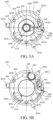
- FIGS. 10 A and 10 B are sectional views of the image stabilizing apparatus 600 .
- FIGS. 10 A and 10 B are sectional views in a case where the lens frame 602 is located at a first shifted position (first withdrawal position) and a second shifted position (second withdrawal position), respectively.
- FIG. 11 illustrates the rotational operation torque of the shift lever 607 .
- the linear guide cylinder 107 has a sliding surface 700 on which the shift lever 607 slides.
- the sliding surface 700 includes a first sliding surface 700 a , a second sliding surface 700 b , a third sliding surface (parallel surface) 700 c , and an engagement portion 701 .
- the shift lever 607 includes a first slider 607 c , a second slider 607 d , a third slider 607 e , and an engagement portion 607 f.
- the shift lens 601 is located on the optical axis.
- the first slider 607 c , the second slider 607 d , and the third slider 607 e are disposed at positions that do not contact the sliding surface 700 , and the shift lever 607 does not rotate.
- the shift lever 607 is supported so that the contact portion 607 b is located in the escape space 602 d where the contact portion 607 b does not contact the first contact surface 602 c .
- the lens frame 602 can move integrally with the shift member 604 in parallel within the plane orthogonal to the optical axis during image stabilization.
- a first preceding contact portion 603 f is provided on the outer circumferential portion of the base member 603 .
- the first preceding contact portion 603 f is disposed in the same phase as the shift lever 607 and on the rear side (imaging plane side) of the second follower 603 e .
- a second preceding contact portion 603 g is provided on the outer circumferential portion of the base member 603 .
- the second preceding contact portion 603 g is disposed in a phase that faces the shift lever 607 with respect to the optical axis, and at least part of the second preceding contact portion 603 g is disposed on the object side of the second follower 603 e .
- the first preceding contact surface 703 and the second preceding contact surface 704 are provided on the inner circumferential surface side of the linear guide cylinder 107 .
- the first preceding contact portion 603 f faces the first preceding contact surface 703
- the second preceding contact portion 603 g faces the second preceding contact surface 704 .
- the shift lever 607 is biased by the lever torsion spring 609 with the lever shaft 608 as a rotation axis.
- the first slider 607 c is biased in the circumferential direction of the linear guide cylinder 107 (arrow C direction in FIGS. 8 A to 8 E ).
- the first sliding surface 700 a is tilted by an angle ⁇ 1 relative to the optical axis. In a case where the first slider 607 c is pressed against the first sliding surface 700 a , the first slider 607 c receives a reaction force from the first sliding surface 700 a in a direction against the lever torsion spring 609 .
- the reaction force from the first sliding surface 700 a increases, and the shift lever 607 starts to rotate about the lever shaft 608 against the biasing force of the lever torsion spring 609 .
- the second slider 607 d and the second sliding surface 700 b contact each other.
- the second sliding surface 700 b is tilted by an angle ⁇ 2 smaller than the angle ⁇ 1 relative to the optical axis.
- the force component in the slope direction (sliding direction) on the second sliding surface 700 b is larger than the force component in the slope direction on the first sliding surface 700 a . That is, the force necessary to slide the second slider 607 d on the second sliding surface 700 b may be smaller than the force necessary to slide the first slider 607 c on the first sliding surface 700 a .
- This embodiment sets the click feeling suitable for operating the zoom operation ring 103 by changing the angle between the first sliding surface 700 a and the second sliding surface 700 b and the biasing force of the lever torsion spring 609 .
- the set click feeling allows the user to recognize the boundary of the phase of the zoom operation ring 103 .
- the contact portion 607 b contacts the first contact surface 602 c .
- the rotation of the shift lever 607 causes the lens frame 602 to shift from the optical axis against the biasing force of the holder torsion spring 606 .
- the lens frame 602 is located at the first shifted position in FIG. 10 A .
- the third sliding surface 700 c is parallel to the optical axis, and the shift lever 607 does not rotate while the third slider 607 e contacts the third sliding surface 700 c .
- the phrase “parallel to the optical axis” includes not only strictly parallel to the optical axis but also substantially parallel (substantially parallel) to the optical axis.
- the first followers are engaged with the cam grooves in the second retraction area 801 c , and the first lens unit 111 approaches the image stabilizing apparatus 600 according to the operation of the zoom operation ring 103 toward the retraction side. Part of the first zoom unit 110 then enters the space created by the retraction of the lens frame 602 . Since the lens frame 602 is located at the first shifted position, it does not contact the part of the first lens unit 111 that has entered the space.
- the engagement portion 607 f slides and is finally engaged with the engagement portion 701 .
- the lens frame 602 is located at the second shifted position.
- the engagement portion 701 is formed as a concave shape on the extension of the third sliding surface 700 c .
- the shift lever 607 is rotated toward the imaging position by the biasing force of the lever torsion spring 609 .
- the lens frame 602 also rotates toward the imaging position due to the biasing force of the holder torsion spring 606 . That is, the second shifted position is closer to the imaging position (optical axis side) than the first shifted position.
- the engagement portion 701 has a convex shape
- the lens frame 602 is shifted from the first shifted position toward the outside.
- the engagement portion 701 having the concave shape can minimize a shift amount of the lens frame 602 and suppress the size increase of the lens barrel 101 .
- the second shifted position is a position at which the rotation of the lens frame 602 toward the imaging position is stopped because the second contact surface 602 e contacts the lens frame contact portion 111 b provided on the lens frame 111 a .
- the contact portion 607 b and the first contact surface 602 c are separated.
- the second contact surface 602 e is more distant from the holder shaft 605 , which is the rotation center, than the first contact surface 602 c .
- the reaction force applied to the lens frame 602 in the retracted state is smaller than the reaction force applied in a case where the rotation is stopped by the shift lever 607 . Thereby, the lens frame 602 is restrained from increasing in size and complicating its shape in order to secure rigidity for creep prevention.
- the shift lever 607 transitions from the state illustrated in FIG. 8 E to the state illustrated in FIG. 8 B through the states illustrated in FIGS. 8 D and 8 C .
- Changing the angle between the engagement portion 607 f and the engagement portion 701 and the biasing force of the lever torsion spring 609 can set unlock torque suitable to operate the zoom operation ring 103 .
- each first follower is engaged with the first retraction area 801 b .
- the first retraction area 801 b is formed so that the gradient relative to the optical axis increases toward the retraction side. That is, the rotational operation torque generated from the sliding of the shift lever 607 during the retraction operation decreases toward the retraction side. Thereby, the rotational operation torque can be made closer to a constant value. As described with reference to FIG.
- the third sliding surface 700 d is formed parallel to the optical axis, and thus the rotational operation torque has a constant value.
- each first follower is engaged with the second retraction area 801 c .
- the tilt angle of the cam groove is constant, and the rotational operation torque generated from the sliding of the shift lever 607 is also constant.
- the shift lever 607 in the retracted state, is engaged with the engagement portion 701 and restricted from further rotating. At this time, the shift lever 607 is smoothly engaged with the engagement portion 701 because the engagement portion 701 has a concave shape.
- the rotational operation torque becomes large only at the wide-angle end during the retraction operation, and thus the user can easily recognize the imaging end and smoothly perform the retraction operation.
- a phase that generates a large rotational operation torque is only at the retraction end where the shift lever 607 escapes from the engagement portion 701 .
- no large rotational operation torque is generated.
- the angles ⁇ 1 and ⁇ 2 and the biasing force of the lever torsion spring 609 are set so that the rotational operation torque becomes smaller while the shift lever 607 transitions from the second sliding surface 700 b to the first sliding surface 700 a .
- the user can recognize the boundary between the retraction area and the imaging area because the rotational operation torque is reduced in the imaging area.
- the user can smoothly operate the zoom operation ring 103 from the retraction area to the imaging area without feeling uncomfortable.
- An unillustrated charge member may be used to adjust the rotational operation torque.
- the charge member is disposed, for example, between the zoom operation ring 103 and an unillustrated fixed cylinder, and changes a charge amount according to the rotational phase of the zoom operation ring 103 .
- the structure according to this embodiment can realize the lens barrel 101 that includes the lock mechanism for the retracted state and the lens shifting mechanism and can suppress the size increase by sharing components.
- first slider 607 c , the second slider 607 d , and the third slider 607 e are formed on a plane in this embodiment, they may be formed in a continuous circular arc shape.
- the third sliding surface 700 c may be tilted at an angle ⁇ 3 smaller than the angle ⁇ 2 relative to the optical axis.
- the third sliding surface 700 c may be omitted, and the second sliding surface 700 b may be connected to the engagement portion 701 .
- the first slider 607 c and the engagement portion 607 f contact the engagement portion 701 , but only the engagement portion 607 f contacts the engagement portion 701 , another component (such as the zoom operation ring 103 and an unillustrated fixed barrel) may restrict the zoom operation ring 103 from rotating toward the retraction side.
- the lens frame 602 may not perform image stabilization. That is, the lens frame 602 may be held by the base member 603 via the holder shaft 605 .
- the shift lever 607 may be integrated with the lens frame 602 .
- the above embodiment can provide a lens barrel that includes the lock mechanism for the retracted state and the lens shifting mechanism and can suppress the size increase.
- the shifting direction of the lens shifting mechanism is not limited to a direction orthogonal to the optical axis of the optical system.
Landscapes
- Physics & Mathematics (AREA)
- Engineering & Computer Science (AREA)
- General Physics & Mathematics (AREA)
- Multimedia (AREA)
- Signal Processing (AREA)
- Optics & Photonics (AREA)
- General Engineering & Computer Science (AREA)
- Lens Barrels (AREA)
- Structure And Mechanism Of Cameras (AREA)
- Adjustment Of Camera Lenses (AREA)
- Studio Devices (AREA)
Abstract
Description
Claims (15)
Applications Claiming Priority (2)
| Application Number | Priority Date | Filing Date | Title |
|---|---|---|---|
| JP2022084561A JP2023172620A (en) | 2022-05-24 | 2022-05-24 | Lens barrel and imaging apparatus |
| JP2022-084561 | 2022-05-24 |
Publications (2)
| Publication Number | Publication Date |
|---|---|
| US20230384553A1 US20230384553A1 (en) | 2023-11-30 |
| US12259593B2 true US12259593B2 (en) | 2025-03-25 |
Family
ID=88877103
Family Applications (1)
| Application Number | Title | Priority Date | Filing Date |
|---|---|---|---|
| US18/317,256 Active 2043-10-18 US12259593B2 (en) | 2022-05-24 | 2023-05-15 | Lens barrel and image pickup apparatus |
Country Status (2)
| Country | Link |
|---|---|
| US (1) | US12259593B2 (en) |
| JP (1) | JP2023172620A (en) |
Citations (4)
| Publication number | Priority date | Publication date | Assignee | Title |
|---|---|---|---|---|
| US7619654B2 (en) * | 2005-02-07 | 2009-11-17 | Fujifilm Corporation | Camera and lens device |
| JP2010286789A (en) | 2009-06-15 | 2010-12-24 | Olympus Imaging Corp | Zoom lens barrel |
| US8773762B2 (en) * | 2011-02-28 | 2014-07-08 | Hoya Corporation | Lens barrel having an image-stabilizing insertable/removable optical element |
| US20150168683A1 (en) * | 2013-12-17 | 2015-06-18 | Canon Kabushiki Kaisha | Optical apparatus capable of retracting optical element from optical path |
-
2022
- 2022-05-24 JP JP2022084561A patent/JP2023172620A/en active Pending
-
2023
- 2023-05-15 US US18/317,256 patent/US12259593B2/en active Active
Patent Citations (5)
| Publication number | Priority date | Publication date | Assignee | Title |
|---|---|---|---|---|
| US7619654B2 (en) * | 2005-02-07 | 2009-11-17 | Fujifilm Corporation | Camera and lens device |
| JP2010286789A (en) | 2009-06-15 | 2010-12-24 | Olympus Imaging Corp | Zoom lens barrel |
| US8773762B2 (en) * | 2011-02-28 | 2014-07-08 | Hoya Corporation | Lens barrel having an image-stabilizing insertable/removable optical element |
| US20150168683A1 (en) * | 2013-12-17 | 2015-06-18 | Canon Kabushiki Kaisha | Optical apparatus capable of retracting optical element from optical path |
| JP2015135472A (en) | 2013-12-17 | 2015-07-27 | キヤノン株式会社 | Optical equipment that can retract optical members from the optical path |
Also Published As
| Publication number | Publication date |
|---|---|
| JP2023172620A (en) | 2023-12-06 |
| US20230384553A1 (en) | 2023-11-30 |
Similar Documents
| Publication | Publication Date | Title |
|---|---|---|
| JP6672696B2 (en) | Lens barrel and camera body | |
| JP4775010B2 (en) | Lens barrel and camera | |
| WO2004031826A1 (en) | Collapsible lens barrel and optical instrument using the same | |
| US12259593B2 (en) | Lens barrel and image pickup apparatus | |
| US11644638B2 (en) | Lens apparatus and image pickup apparatus | |
| US11399128B2 (en) | Position detecting apparatus for acquiring a rotational position of a rotating member | |
| JP6984675B2 (en) | Lens barrel and camera body | |
| US12149823B2 (en) | Optical apparatus and camera system | |
| US20230266562A1 (en) | Lens barrel, lens apparatus and image pickup apparatus | |
| US20250180853A1 (en) | Lens apparatus and imaging system | |
| US20230055253A1 (en) | Optical apparatus, image stabilization device, lens barrel, and image pickup apparatus | |
| US20250102888A1 (en) | Optical apparatus | |
| US20250035883A1 (en) | Optical apparatus | |
| JP7710335B2 (en) | Optical equipment, imaging devices | |
| US20250224588A1 (en) | Lens apparatus and image pickup apparatus | |
| JP7433948B2 (en) | optical equipment | |
| JP7328285B2 (en) | optical equipment | |
| JP2023026223A (en) | Optical instrument, lens barrel and imaging device | |
| JP2022164960A (en) | OPTICAL DEVICE AND IMAGING DEVICE HAVING THE SAME | |
| US12085776B2 (en) | Apparatus and system | |
| JP7580928B2 (en) | Lens device and imaging device | |
| JP2025093617A (en) | Lens device and imaging system | |
| JP2023061696A (en) | Optical instrument | |
| JP2023110540A (en) | Lens barrel, optical apparatus, and camera system | |
| JP2025047840A (en) | Optical Instruments |
Legal Events
| Date | Code | Title | Description |
|---|---|---|---|
| FEPP | Fee payment procedure |
Free format text: ENTITY STATUS SET TO UNDISCOUNTED (ORIGINAL EVENT CODE: BIG.); ENTITY STATUS OF PATENT OWNER: LARGE ENTITY |
|
| AS | Assignment |
Owner name: CANON KABUSHIKI KAISHA, JAPAN Free format text: ASSIGNMENT OF ASSIGNORS INTEREST;ASSIGNOR:UEMURA, KOHEI;REEL/FRAME:063901/0347 Effective date: 20230424 |
|
| STPP | Information on status: patent application and granting procedure in general |
Free format text: DOCKETED NEW CASE - READY FOR EXAMINATION |
|
| STPP | Information on status: patent application and granting procedure in general |
Free format text: NOTICE OF ALLOWANCE MAILED -- APPLICATION RECEIVED IN OFFICE OF PUBLICATIONS |
|
| STPP | Information on status: patent application and granting procedure in general |
Free format text: PUBLICATIONS -- ISSUE FEE PAYMENT RECEIVED |
|
| STPP | Information on status: patent application and granting procedure in general |
Free format text: PUBLICATIONS -- ISSUE FEE PAYMENT VERIFIED |
|
| STCF | Information on status: patent grant |
Free format text: PATENTED CASE |