US12258003B2 - Vehicle control apparatus - Google Patents
Vehicle control apparatus Download PDFInfo
- Publication number
- US12258003B2 US12258003B2 US17/692,412 US202217692412A US12258003B2 US 12258003 B2 US12258003 B2 US 12258003B2 US 202217692412 A US202217692412 A US 202217692412A US 12258003 B2 US12258003 B2 US 12258003B2
- Authority
- US
- United States
- Prior art keywords
- state
- engine
- controlled
- traveling mode
- vehicle
- Prior art date
- Legal status (The legal status is an assumption and is not a legal conclusion. Google has not performed a legal analysis and makes no representation as to the accuracy of the status listed.)
- Active, expires
Links
Images


Classifications
-
- B—PERFORMING OPERATIONS; TRANSPORTING
- B60—VEHICLES IN GENERAL
- B60W—CONJOINT CONTROL OF VEHICLE SUB-UNITS OF DIFFERENT TYPE OR DIFFERENT FUNCTION; CONTROL SYSTEMS SPECIALLY ADAPTED FOR HYBRID VEHICLES; ROAD VEHICLE DRIVE CONTROL SYSTEMS FOR PURPOSES NOT RELATED TO THE CONTROL OF A PARTICULAR SUB-UNIT
- B60W30/00—Purposes of road vehicle drive control systems not related to the control of a particular sub-unit, e.g. of systems using conjoint control of vehicle sub-units
- B60W30/18—Propelling the vehicle
- B60W30/20—Reducing vibrations in the driveline
-
- B—PERFORMING OPERATIONS; TRANSPORTING
- B60—VEHICLES IN GENERAL
- B60K—ARRANGEMENT OR MOUNTING OF PROPULSION UNITS OR OF TRANSMISSIONS IN VEHICLES; ARRANGEMENT OR MOUNTING OF PLURAL DIVERSE PRIME-MOVERS IN VEHICLES; AUXILIARY DRIVES FOR VEHICLES; INSTRUMENTATION OR DASHBOARDS FOR VEHICLES; ARRANGEMENTS IN CONNECTION WITH COOLING, AIR INTAKE, GAS EXHAUST OR FUEL SUPPLY OF PROPULSION UNITS IN VEHICLES
- B60K6/00—Arrangement or mounting of plural diverse prime-movers for mutual or common propulsion, e.g. hybrid propulsion systems comprising electric motors and internal combustion engines
- B60K6/20—Arrangement or mounting of plural diverse prime-movers for mutual or common propulsion, e.g. hybrid propulsion systems comprising electric motors and internal combustion engines the prime-movers consisting of electric motors and internal combustion engines, e.g. HEVs
- B60K6/22—Arrangement or mounting of plural diverse prime-movers for mutual or common propulsion, e.g. hybrid propulsion systems comprising electric motors and internal combustion engines the prime-movers consisting of electric motors and internal combustion engines, e.g. HEVs characterised by apparatus, components or means specially adapted for HEVs
- B60K6/38—Arrangement or mounting of plural diverse prime-movers for mutual or common propulsion, e.g. hybrid propulsion systems comprising electric motors and internal combustion engines the prime-movers consisting of electric motors and internal combustion engines, e.g. HEVs characterised by apparatus, components or means specially adapted for HEVs characterised by the driveline clutches
- B60K6/387—Actuated clutches, i.e. clutches engaged or disengaged by electric, hydraulic or mechanical actuating means
-
- B—PERFORMING OPERATIONS; TRANSPORTING
- B60—VEHICLES IN GENERAL
- B60W—CONJOINT CONTROL OF VEHICLE SUB-UNITS OF DIFFERENT TYPE OR DIFFERENT FUNCTION; CONTROL SYSTEMS SPECIALLY ADAPTED FOR HYBRID VEHICLES; ROAD VEHICLE DRIVE CONTROL SYSTEMS FOR PURPOSES NOT RELATED TO THE CONTROL OF A PARTICULAR SUB-UNIT
- B60W10/00—Conjoint control of vehicle sub-units of different type or different function
- B60W10/02—Conjoint control of vehicle sub-units of different type or different function including control of driveline clutches
-
- B—PERFORMING OPERATIONS; TRANSPORTING
- B60—VEHICLES IN GENERAL
- B60W—CONJOINT CONTROL OF VEHICLE SUB-UNITS OF DIFFERENT TYPE OR DIFFERENT FUNCTION; CONTROL SYSTEMS SPECIALLY ADAPTED FOR HYBRID VEHICLES; ROAD VEHICLE DRIVE CONTROL SYSTEMS FOR PURPOSES NOT RELATED TO THE CONTROL OF A PARTICULAR SUB-UNIT
- B60W10/00—Conjoint control of vehicle sub-units of different type or different function
- B60W10/04—Conjoint control of vehicle sub-units of different type or different function including control of propulsion units
- B60W10/06—Conjoint control of vehicle sub-units of different type or different function including control of propulsion units including control of combustion engines
-
- B—PERFORMING OPERATIONS; TRANSPORTING
- B60—VEHICLES IN GENERAL
- B60W—CONJOINT CONTROL OF VEHICLE SUB-UNITS OF DIFFERENT TYPE OR DIFFERENT FUNCTION; CONTROL SYSTEMS SPECIALLY ADAPTED FOR HYBRID VEHICLES; ROAD VEHICLE DRIVE CONTROL SYSTEMS FOR PURPOSES NOT RELATED TO THE CONTROL OF A PARTICULAR SUB-UNIT
- B60W10/00—Conjoint control of vehicle sub-units of different type or different function
- B60W10/04—Conjoint control of vehicle sub-units of different type or different function including control of propulsion units
- B60W10/08—Conjoint control of vehicle sub-units of different type or different function including control of propulsion units including control of electric propulsion units, e.g. motors or generators
-
- B—PERFORMING OPERATIONS; TRANSPORTING
- B60—VEHICLES IN GENERAL
- B60W—CONJOINT CONTROL OF VEHICLE SUB-UNITS OF DIFFERENT TYPE OR DIFFERENT FUNCTION; CONTROL SYSTEMS SPECIALLY ADAPTED FOR HYBRID VEHICLES; ROAD VEHICLE DRIVE CONTROL SYSTEMS FOR PURPOSES NOT RELATED TO THE CONTROL OF A PARTICULAR SUB-UNIT
- B60W10/00—Conjoint control of vehicle sub-units of different type or different function
- B60W10/10—Conjoint control of vehicle sub-units of different type or different function including control of change-speed gearings
- B60W10/101—Infinitely variable gearings
- B60W10/107—Infinitely variable gearings with endless flexible members
-
- B—PERFORMING OPERATIONS; TRANSPORTING
- B60—VEHICLES IN GENERAL
- B60W—CONJOINT CONTROL OF VEHICLE SUB-UNITS OF DIFFERENT TYPE OR DIFFERENT FUNCTION; CONTROL SYSTEMS SPECIALLY ADAPTED FOR HYBRID VEHICLES; ROAD VEHICLE DRIVE CONTROL SYSTEMS FOR PURPOSES NOT RELATED TO THE CONTROL OF A PARTICULAR SUB-UNIT
- B60W20/00—Control systems specially adapted for hybrid vehicles
- B60W20/10—Controlling the power contribution of each of the prime movers to meet required power demand
- B60W20/15—Control strategies specially adapted for achieving a particular effect
-
- B—PERFORMING OPERATIONS; TRANSPORTING
- B60—VEHICLES IN GENERAL
- B60W—CONJOINT CONTROL OF VEHICLE SUB-UNITS OF DIFFERENT TYPE OR DIFFERENT FUNCTION; CONTROL SYSTEMS SPECIALLY ADAPTED FOR HYBRID VEHICLES; ROAD VEHICLE DRIVE CONTROL SYSTEMS FOR PURPOSES NOT RELATED TO THE CONTROL OF A PARTICULAR SUB-UNIT
- B60W20/00—Control systems specially adapted for hybrid vehicles
- B60W20/40—Controlling the engagement or disengagement of prime movers, e.g. for transition between prime movers
-
- B—PERFORMING OPERATIONS; TRANSPORTING
- B60—VEHICLES IN GENERAL
- B60W—CONJOINT CONTROL OF VEHICLE SUB-UNITS OF DIFFERENT TYPE OR DIFFERENT FUNCTION; CONTROL SYSTEMS SPECIALLY ADAPTED FOR HYBRID VEHICLES; ROAD VEHICLE DRIVE CONTROL SYSTEMS FOR PURPOSES NOT RELATED TO THE CONTROL OF A PARTICULAR SUB-UNIT
- B60W30/00—Purposes of road vehicle drive control systems not related to the control of a particular sub-unit, e.g. of systems using conjoint control of vehicle sub-units
- B60W30/18—Propelling the vehicle
- B60W30/182—Selecting between different operative modes, e.g. comfort and performance modes
-
- B—PERFORMING OPERATIONS; TRANSPORTING
- B60—VEHICLES IN GENERAL
- B60W—CONJOINT CONTROL OF VEHICLE SUB-UNITS OF DIFFERENT TYPE OR DIFFERENT FUNCTION; CONTROL SYSTEMS SPECIALLY ADAPTED FOR HYBRID VEHICLES; ROAD VEHICLE DRIVE CONTROL SYSTEMS FOR PURPOSES NOT RELATED TO THE CONTROL OF A PARTICULAR SUB-UNIT
- B60W30/00—Purposes of road vehicle drive control systems not related to the control of a particular sub-unit, e.g. of systems using conjoint control of vehicle sub-units
- B60W30/18—Propelling the vehicle
- B60W30/19—Improvement of gear change, e.g. by synchronisation or smoothing gear shift
-
- B—PERFORMING OPERATIONS; TRANSPORTING
- B60—VEHICLES IN GENERAL
- B60K—ARRANGEMENT OR MOUNTING OF PROPULSION UNITS OR OF TRANSMISSIONS IN VEHICLES; ARRANGEMENT OR MOUNTING OF PLURAL DIVERSE PRIME-MOVERS IN VEHICLES; AUXILIARY DRIVES FOR VEHICLES; INSTRUMENTATION OR DASHBOARDS FOR VEHICLES; ARRANGEMENTS IN CONNECTION WITH COOLING, AIR INTAKE, GAS EXHAUST OR FUEL SUPPLY OF PROPULSION UNITS IN VEHICLES
- B60K6/00—Arrangement or mounting of plural diverse prime-movers for mutual or common propulsion, e.g. hybrid propulsion systems comprising electric motors and internal combustion engines
- B60K6/20—Arrangement or mounting of plural diverse prime-movers for mutual or common propulsion, e.g. hybrid propulsion systems comprising electric motors and internal combustion engines the prime-movers consisting of electric motors and internal combustion engines, e.g. HEVs
- B60K6/42—Arrangement or mounting of plural diverse prime-movers for mutual or common propulsion, e.g. hybrid propulsion systems comprising electric motors and internal combustion engines the prime-movers consisting of electric motors and internal combustion engines, e.g. HEVs characterised by the architecture of the hybrid electric vehicle
- B60K6/48—Parallel type
- B60K2006/4825—Electric machine connected or connectable to gearbox input shaft
-
- B—PERFORMING OPERATIONS; TRANSPORTING
- B60—VEHICLES IN GENERAL
- B60W—CONJOINT CONTROL OF VEHICLE SUB-UNITS OF DIFFERENT TYPE OR DIFFERENT FUNCTION; CONTROL SYSTEMS SPECIALLY ADAPTED FOR HYBRID VEHICLES; ROAD VEHICLE DRIVE CONTROL SYSTEMS FOR PURPOSES NOT RELATED TO THE CONTROL OF A PARTICULAR SUB-UNIT
- B60W30/00—Purposes of road vehicle drive control systems not related to the control of a particular sub-unit, e.g. of systems using conjoint control of vehicle sub-units
- B60W30/18—Propelling the vehicle
- B60W30/20—Reducing vibrations in the driveline
- B60W2030/203—Reducing vibrations in the driveline related or induced by the clutch
-
- B—PERFORMING OPERATIONS; TRANSPORTING
- B60—VEHICLES IN GENERAL
- B60W—CONJOINT CONTROL OF VEHICLE SUB-UNITS OF DIFFERENT TYPE OR DIFFERENT FUNCTION; CONTROL SYSTEMS SPECIALLY ADAPTED FOR HYBRID VEHICLES; ROAD VEHICLE DRIVE CONTROL SYSTEMS FOR PURPOSES NOT RELATED TO THE CONTROL OF A PARTICULAR SUB-UNIT
- B60W2510/00—Input parameters relating to a particular sub-units
- B60W2510/06—Combustion engines, Gas turbines
- B60W2510/0657—Engine torque
-
- B—PERFORMING OPERATIONS; TRANSPORTING
- B60—VEHICLES IN GENERAL
- B60W—CONJOINT CONTROL OF VEHICLE SUB-UNITS OF DIFFERENT TYPE OR DIFFERENT FUNCTION; CONTROL SYSTEMS SPECIALLY ADAPTED FOR HYBRID VEHICLES; ROAD VEHICLE DRIVE CONTROL SYSTEMS FOR PURPOSES NOT RELATED TO THE CONTROL OF A PARTICULAR SUB-UNIT
- B60W2520/00—Input parameters relating to overall vehicle dynamics
- B60W2520/10—Longitudinal speed
- B60W2520/105—Longitudinal acceleration
-
- B—PERFORMING OPERATIONS; TRANSPORTING
- B60—VEHICLES IN GENERAL
- B60W—CONJOINT CONTROL OF VEHICLE SUB-UNITS OF DIFFERENT TYPE OR DIFFERENT FUNCTION; CONTROL SYSTEMS SPECIALLY ADAPTED FOR HYBRID VEHICLES; ROAD VEHICLE DRIVE CONTROL SYSTEMS FOR PURPOSES NOT RELATED TO THE CONTROL OF A PARTICULAR SUB-UNIT
- B60W2710/00—Output or target parameters relating to a particular sub-units
- B60W2710/06—Combustion engines, Gas turbines
- B60W2710/0666—Engine torque
-
- B—PERFORMING OPERATIONS; TRANSPORTING
- B60—VEHICLES IN GENERAL
- B60W—CONJOINT CONTROL OF VEHICLE SUB-UNITS OF DIFFERENT TYPE OR DIFFERENT FUNCTION; CONTROL SYSTEMS SPECIALLY ADAPTED FOR HYBRID VEHICLES; ROAD VEHICLE DRIVE CONTROL SYSTEMS FOR PURPOSES NOT RELATED TO THE CONTROL OF A PARTICULAR SUB-UNIT
- B60W2710/00—Output or target parameters relating to a particular sub-units
- B60W2710/08—Electric propulsion units
- B60W2710/083—Torque
-
- B—PERFORMING OPERATIONS; TRANSPORTING
- B60—VEHICLES IN GENERAL
- B60W—CONJOINT CONTROL OF VEHICLE SUB-UNITS OF DIFFERENT TYPE OR DIFFERENT FUNCTION; CONTROL SYSTEMS SPECIALLY ADAPTED FOR HYBRID VEHICLES; ROAD VEHICLE DRIVE CONTROL SYSTEMS FOR PURPOSES NOT RELATED TO THE CONTROL OF A PARTICULAR SUB-UNIT
- B60W2710/00—Output or target parameters relating to a particular sub-units
- B60W2710/10—Change speed gearings
- B60W2710/1005—Transmission ratio engaged
-
- Y—GENERAL TAGGING OF NEW TECHNOLOGICAL DEVELOPMENTS; GENERAL TAGGING OF CROSS-SECTIONAL TECHNOLOGIES SPANNING OVER SEVERAL SECTIONS OF THE IPC; TECHNICAL SUBJECTS COVERED BY FORMER USPC CROSS-REFERENCE ART COLLECTIONS [XRACs] AND DIGESTS
- Y02—TECHNOLOGIES OR APPLICATIONS FOR MITIGATION OR ADAPTATION AGAINST CLIMATE CHANGE
- Y02T—CLIMATE CHANGE MITIGATION TECHNOLOGIES RELATED TO TRANSPORTATION
- Y02T10/00—Road transport of goods or passengers
- Y02T10/60—Other road transportation technologies with climate change mitigation effect
- Y02T10/62—Hybrid vehicles
Definitions
- the disclosure relates to a vehicle control apparatus configured to control a vehicle.
- a hybrid vehicle is equipped with an engine and a motor generator as power sources (see Japanese Unexamined Patent Application Nos. H10-98804, 2005-130564 and 2014-196104).
- the hybrid vehicle has, as traveling modes Publication, an electric vehicle (EV) mode to travel using a motor generator, and a hybrid electric vehicle (HEV) mode to travel using an engine and the motor generator.
- EV electric vehicle
- HEV hybrid electric vehicle
- An aspect of the disclosure provides a vehicle control apparatus configured to control a vehicle.
- the vehicle control apparatus includes a motor generator, an engine, a transmission mechanism, a clutch mechanism, and a control system.
- the motor generator is coupled to a first drive wheel; an engine coupled to at least one of the first drive wheel and a second drive wheel via a power transmission path.
- the transmission mechanism is disposed in the power transmission path.
- the clutch mechanism is disposed in the power transmission path between the engine and the transmission mechanism.
- the control system includes a processor and a memory communicably coupled to each other and configured to control the motor generator, the engine, the transmission mechanism and the clutch mechanism.
- the control system has a first traveling mode and a second traveling mode.
- the first traveling mode is to control the clutch mechanism to be in an engagement state, control the engine to be in a driving state and control the motor generator to be in a rotation state.
- the second traveling mode is to control the clutch mechanism to be in a disengagement state, control the engine to be in a stopped state, and control the motor generator to be in the rotation state.
- the control system is configured to set a shift period based on a transmission gear ratio of the transmission mechanism.
- the control system is configured to: control, upon switching from the first traveling mode to the second traveling mode, the clutch mechanism to be in a state where the clutch mechanism is engaged for an entirety of the shift period; and under the state where the clutch mechanism is engaged, decrease a torque of the engine and increase a power running torque of the motor generator.
- FIG. 1 illustrates a configuration example of a vehicle including a vehicle control apparatus according to an embodiment of the disclosure
- FIG. 2 illustrates a configuration example of the vehicle control apparatus
- FIG. 3 simply illustrates a basic structure of each control unit
- FIG. 4 illustrates a state of executing an EV mode
- FIG. 5 A illustrates a state of executing a HEV mode
- FIG. 5 B illustrates a state of executing a HEV mode
- FIG. 6 is a traveling mode map illustrating an example of regions for executing the EV and HEV modes
- FIG. 7 is a flowchart indicating an example of a procedure for executing traveling mode switching control
- FIG. 8 illustrates an example of relationship between a transmission gear ratio and a first time period
- FIG. 9 illustrates an example of relationship between a vehicle acceleration rate and a second time period
- FIG. 10 illustrates an example of relationship between an engine torque and a third time period
- FIG. 11 is a timing chart illustrating a state of executing traveling mode switching control according to an embodiment of the disclosure.
- FIG. 12 is a timing chart illustrating a state of executing traveling mode switching control according to a comparative example
- FIG. 13 is a timing chart illustrating a state of executing traveling mode switching control according to an embodiment of the disclosure
- FIG. 14 illustrates a configuration example of a power train
- FIG. 15 illustrates a configuration example of the power train.
- FIG. 1 illustrates a configuration example of a vehicle 11 including a vehicle control apparatus 10 according to an embodiment of the disclosure.
- the vehicle 11 is equipped with a power train 14 including an engine 12 and a transmission 13 .
- the illustrated vehicle 11 is a hybrid vehicle, and a motor generator 15 as a power source is mounted on the transmission 13 .
- an output shaft 16 of the transmission 13 is coupled to rear wheels 19 r via a propeller shaft 17 and a differential mechanism 18 .
- the illustrated power train 14 is a power train for rear wheel drive that drives the rear wheels 19 r , but the disclosure is not limited thereto.
- the power train 14 may be a power train for front wheel drive that drives front wheels 19 f , or may be a power train for all-wheel-drive that drives both the front wheels 19 f and the rear wheels 19 r .
- each of the rear wheels 19 r may serve as a “first drive wheel”
- each of the front wheels 19 f may server as a “second drive wheel”.
- FIG. 2 illustrates a configuration example of the vehicle control apparatus 10 .
- the power train 14 is equipped with a continuously variable transmission mechanism 22 including a primary pulley 20 , a secondary pulley 21 and a driving chain 27 .
- the engine 12 is coupled to one side of a primary shaft 23 supporting the primary pulley 20 via a forward clutch 24 and a torque converter 25 .
- the other side of the primary shaft 23 supporting the primary pulley 20 is coupled to a rotor 15 r of the motor generator 15 .
- a secondary shaft 26 supporting the secondary pulley 21 is coupled to the rear wheels 19 r via the output shaft 16 , the propeller shaft 17 and the differential mechanism 18 .
- the continuously variable transmission mechanism 22 and the forward clutch 24 may serve as a “transmission mechanism”, and “clutch mechanism” respectively.
- forward clutch 24 is a clutch forming part of a forward and reverse switching mechanism.
- the engine 12 is coupled to the rear wheels 19 r via a power transmission path 30 that includes the torque converter 25 , the forward clutch 24 , the continuously variable transmission mechanism 22 , the propeller shaft 17 , the differential mechanism 18 and other components.
- the power transmission path 30 includes a crank shaft 31 , the torque converter 25 , a turbine shaft 32 , the forward clutch 24 , the primary shaft 23 , the continuously variable transmission mechanism 22 , the secondary shaft 26 , the output shaft 16 , the propeller shaft 17 , and the differential mechanism 18 .
- the forward clutch 24 and the continuously variable transmission mechanism 22 are provided to the power transmission path 30 , which couples the engine 12 to the rear wheels 19 r .
- the forward clutch 24 on the power transmission path 30 is disposed between the engine 12 and the continuously variable transmission mechanism 22 .
- the motor generator 15 is coupled to the primary shaft 23 forming the power transmission path 30 . That is, the motor generator 15 is coupled to the rear wheels 19 r from an input side of the continuously variable transmission mechanism 22 via the power transmission path 30 .
- a throttle valve 41 configured to regulate an intake air amount is provided to an intake manifold 40 of the engine 12 .
- the engine 12 is equipped with an injector 42 that injects a fuel into an intake port or a cylinder, and is also equipped with an ignition device 43 including an ignitor, an ignition plug and other components.
- the engine 12 is equipped with an engine rotation sensor 44 that detects an engine rotation speed.
- an engine control unit CU 1 that is an electronic control unit is coupled to the components of the engine 12 such as the throttle valve 41 , the injector 42 , and the ignition device 43 .
- the power train 14 is equipped with a valve unit 45 including multiple solenoid valves, oil passages and other components.
- the valve unit 45 is coupled to an oil pump 46 driven by an engine or the like. Hydraulic oil discharged from the oil pump 46 is controlled by the valve unit 45 in terms of the supply destination, the pressure or the like, so that the hydraulic oil is supplied to the forward clutch 24 , the continuously variable transmission mechanism 22 and the like.
- the valve unit 45 is coupled to a transmission control unit CU 2 that is an electronic control unit.
- the transmission control unit CU 2 is coupled to a primary rotation sensor 47 that detects a rotation speed of the primary pulley 20 and a secondary rotation sensor 48 that detects a rotation speed of the secondary pulley 21 .
- a stator 15 s of the motor generator 15 is coupled to a battery module 51 via an inverter 50 .
- Multiple battery cells 53 forming a high-voltage battery 52 are mounted on the battery module 51 .
- the battery module 51 further includes components such as main relays 54 that control the connection of the high-voltage battery 52 , and a battery sensor 55 that detects charge and discharge currents, a terminal voltage, a temperature and the like.
- the battery module 51 is coupled to a battery control unit CU 3 that is an electronic control unit. The battery control unit CU 3 monitors charge and discharge of the high-voltage battery 52 and controls the main relays 54 and other components.
- the battery control unit CU 3 calculates a state of charge (SOC) of the high-voltage battery 52 based on the charge and discharge currents, the terminal voltage, etc., which are detected by the battery sensor 55 .
- SOC state of charge
- the SOC of the high-voltage battery 52 is a ratio indicating a remaining amount of electricity in the high-voltage battery 52 , or a ratio of charged amount to the full charge capacity of the high-voltage battery 52 .
- the inverter 50 executes energization control of the motor generator 15 , and is coupled to a motor control unit CU 4 that is an electronic control unit.
- the motor control unit CU 4 controls the inverter 50 including multiple switching elements, thereby controlling a motor torque outputted from the motor generator 15 .
- the motor torque of the motor generator 15 includes a power running torque outputted from the motor generator 15 in a power running state, and a power generation torque outputted from the motor generator 15 in a power generation state.
- the direction of action of the power running torque is opposite to the direction of action of the power generation torque.
- DC power from the high-voltage battery 52 is converted into AC power via the inverter 50 , and supplied to the stator 15 s .
- AC power from the stator 15 s is converted into DC power via the inverter 50 , and supplied to the high-voltage battery 52 .
- the vehicle control apparatus 10 is equipped with a control system 60 that includes multiple electronic control units to control the power train 14 .
- the electronic control units forming the control system 60 include the above-described engine control unit CU 1 , transmission control unit CU 2 , battery control unit CU 3 and motor control unit CU 4 .
- the electronic control units forming the control system 60 further include a vehicle control unit CU 5 that outputs control signals to each of the control units CU 1 to CU 4 .
- These control units CU 1 to CU 5 are communicably coupled to one another via an in-vehicle network 61 such as controller area network (CAN).
- CAN controller area network
- the vehicle control unit CU 5 sets an operation target of the power train 14 based on information inputted from the control units CU 1 to CU 4 and later-described various sensors. Then, the vehicle control unit CU 5 generates control signals according to the operation target of the power train 14 and outputs these control signals to the control units.
- Examples of the various sensors coupled to the vehicle control unit CU 5 include a vehicle speed sensor 62 that detects a vehicle speed as a traveling speed of the vehicle 11 , an accelerator sensor 63 that detects an operation amount of an accelerator pedal, and a brake sensor 64 that detects an operation amount of a brake pedal.
- the vehicle control unit CU 5 is coupled to an acceleration rate sensor 65 that detects a vehicle acceleration rate acting in a frontward or backward of the vehicle 11 .
- the vehicle control unit CU 5 is coupled to a start switch 66 that is operated by a driver who drives the vehicle 11 at the time of activating the control system 60 .
- FIG. 3 simply illustrates a basic structure of each of the control units CU 1 to CU 5 .
- each of the control units CU 1 to CU 5 includes a micro controller 72 that includes components such as a processor 70 and a memory 71 .
- the memory 71 stores a predetermined program, and the processor 70 executes a set of instructions of the program.
- the processor 70 and the memory 71 are communicably coupled to each other.
- the micro controller 72 includes one processor 70 and one memory 71 , but the disclosure is not limited thereto.
- the micro controller 72 may include multiple processors 70 , and it may include multiple memories 71 .
- each of the control units CU 1 to CU 5 is equipped with various circuits such as an input conversion circuit 73 , a drive circuit 74 , a communication circuit 75 , an external memory 76 , and a power circuit 77 .
- the input conversion circuit 73 converts signals inputted from various sensors into signals that can be inputted into the micro controller 72 .
- the drive circuit 74 generates a drive signal to an actuator such as the above-described valve unit 45 based on the signal outputted from the micro controller 72 .
- the communication circuit 75 converts the signal outputted from the micro controller 72 into a communication signal to be outputted to other control units. In addition, the communication circuit 75 converts a communication signal received from another control unit into a signal that can be inputted into the micro controller 72 .
- the power circuit 77 supplies a stable power source voltage to the micro controller 72 , the input conversion circuit 73 , the drive circuit 74 , the communication circuit 75 , the external memory 76 or the like.
- the external memory 76 such as a non-volatile memory stores data that should be held during non-energization.
- FIG. 4 illustrates a state of executing an electric vehicle (EV) mode
- FIGS. 5 A and 5 B each illustrate a state of executing a hybrid electric vehicle (HEV) mode.
- the control system 60 has, as traveling modes, the EV mode and the HEV mode.
- the EV mode is a traveling mode in which the engine 12 is stopped and the motor generator 15 is operated
- the HEV mode is a traveling mode in which the engine 12 and the motor generator 15 are operated.
- the HEV mode may be referred to a “first traveling mode” and the EV mode may be referred to a “second traveling mode”.
- the control system 60 controls the forward clutch 24 to be in a disengagement state, controls the engine 12 to be in a stopped state, and controls the motor generator 15 to be in a power running state that may be referred to as a rotation state.
- a power running torque to be transmitted to the rear wheels 19 r as indicated by a hollow arrow in FIG. 4 , which allows the vehicle 11 to travel with the motor generator 15 .
- the control system 60 controls the motor generator 15 to be in a regenerative power generation state, whereby kinetic energy of the vehicle 11 is converted into electrical energy and stored in the high-voltage battery 52 .
- control system 60 has, as the HEV mode, an assist mode to control the motor generator 15 to be in the power running state and a power generation-traveling mode to control the motor generator 15 to be in the power generation state.
- the control system 60 controls the forward clutch 24 to be in an engagement state, controls the engine 12 to be in a driving state, and controls the motor generator 15 to be in the power running state (rotation state). This enables the engine torque and the power running torque to be transmitted to the rear wheels 19 r as indicated by hollow arrows in FIG. 5 A , which allows the vehicle 11 to travel with the engine 12 and the motor generator 15 .
- the control system 60 controls the motor generator 15 to be in the regenerative power generation state, whereby kinetic energy of the vehicle 11 is converted into electrical energy and stored in the high-voltage battery 52 .
- the control system 60 controls the forward clutch 24 to be in the engagement state, controls the engine 12 to be in the driving state, and controls the motor generator 15 to be in the power generation state (rotation state).
- This enables the engine torque to be transmitted to the rear wheels 19 r and also to the motor generator 15 as indicated by hollow arrows in FIG. 5 B . That is, while the engine torque is used to operate the motor generator 15 in the power generation state, the engine torque is also used to allow the vehicle 11 to travel.
- FIG. 6 is a traveling mode map illustrating an example for regions of executing the EV and HEV modes. As illustrated in FIG. 6 , the traveling mode map has a boundary line L 1 between a region of executing the EV mode and a region of executing HEV mode.
- a required driving force illustrated in FIG. 6 is a driving force required for the power train 14 by the control system 60 .
- the control system 60 can set the required driving force based on, for example, an accelerator opening that is the operation amount of the accelerator pedal. That is, as the accelerator opening is increased, a larger required driving force is set, and as the accelerator opening is decreased, a smaller required driving force is set.
- the control system 60 switches the traveling mode from the HEV mode to the EV mode. That is, in the case of traveling in the assist mode, the assist mode is switched to the EV mode, and in the case of traveling in the power generation-traveling mode, the power generation-traveling mode is switched to the EV mode.
- the traveling mode is switched from the EV mode to the HEV mode.
- the HEV mode includes the assist mode and the power generation-traveling mode, and which of the assist mode and the power generation-traveling mode is to be executed is determined based on the SOC of the high-voltage battery 52 or the like. For example, when the required driving force or the vehicle speed is increased above the boundary line L 1 and the SOC of the high-voltage battery 52 is higher than a predetermined value, the traveling mode is switched from the EV mode to the assist mode. When the required driving force or the vehicle speed is increased above the boundary line L 1 and the SOC of the high-voltage battery 52 is below the predetermined value, the traveling mode is switched from the EV mode to the power generation-traveling mode.
- FIG. 7 is a flowchart illustrating an example of a procedure for executing the traveling mode switching control.
- FIG. 8 illustrates an example of a relationship between a transmission gear ratio and a first time period T 1 .
- FIG. 9 illustrates an example of a relationship between the vehicle acceleration rate and a second time period T 2 .
- FIG. 10 illustrates an example of a relationship between the engine torque and a third time period T 3 .
- each step in the flowchart of FIG. 7 illustrates processing to be executed by one or multiple processors 70 forming the control system 60 .
- the traveling mode switching control illustrated in FIG. 7 is executed by the control system 60 at every predetermined cycle after the start switch 66 is operated by the driver of the vehicle 11 to activate the control system 60 including the vehicle control unit CU 5 and others.
- step S 10 the control system 60 determines whether the HEV mode is being executed. That is, in step S 10 , the control system 60 determines whether the assist mode or the power generation-traveling mode is being executed. When it is determined in step S 10 that the HEV mode is being executed, the flow proceeds to step S 11 where the control system 60 determines whether a first shift flag is set to an ON state.
- the first shift flag is a control flag that is set to the ON state when the switching from the HEV mode to EV mode is confirmed.
- the first shift flag is set to the ON state at the timing when the traveling state of the vehicle 11 falls below the boundary line L 1 by a reduction in the required driving force or the vehicle speed in the HEV mode, as illustrated by a symbol x 1 in FIG. 6 .
- step S 11 When it is determined in step S 11 that the first shift flag is set to the ON state, the flow proceeds to step S 12 where the control system 60 sets a shift period Tt.
- step S 12 the control system 60 sets the first time period T 1 , the second time period T 2 and the third time period T 3 based on the transmission gear ratio, the vehicle acceleration rate and the engine torque, and then sets the shift period Tt by adding these time periods T 1 , T 2 and T 3 .
- the first time period T 1 forming the shift period Tt is set longer.
- the second time period T 2 is set shorter, and as the vehicle acceleration rate changes further toward a deceleration side (minus side), the second time period T 2 is set shorter. That is, referring to FIG. 9 , as the absolute value of the vehicle acceleration rate becomes smaller, the second time period T 2 forming the shift period Tt is set longer. Further, referring to FIG. 10 , as the engine torque becomes larger, the third time period T 3 forming the shift period Tt is set longer.
- the transmission gear ratio of the continuously variable transmission 22 is calculated by the transmission control unit CU 2 , the engine torque is calculated by the engine control unit CU 1 , and the vehicle acceleration rate is detected by the acceleration rate sensor 65 .
- the transmission gear ratio of the continuously variable transmission mechanism 22 is a ratio of an output rotation speed to an input rotation speed, that is a ratio of a rotation speed of the primary shaft 23 to a rotation speed of the secondary shaft 26 .
- a change of the transmission gear ratio to a low side means that the value of the transmission gear ratio becomes larger, while a change of the transmission gear ratio to a high side means that the value of the transmission gear ratio becomes smaller.
- step S 13 the control system 60 executes a mode switching process.
- the control system 60 controls the forward clutch 24 to be in the engagement state, decreases the engine torque, and increases the power running torque of the motor generator 15 .
- step S 14 the control system 60 determines whether the shift period Tt has elapsed from the start of the mode switching process. If it is determined in step S 14 that the shift period Tt has not elapsed, the flow returns to step S 13 where the control system 60 continues to execute the mode switching process.
- step S 14 determines whether the shift period Tt has elapsed. If it is determined in step S 14 that the shift period Tt has elapsed, the flow proceeds to step S 15 where the control system 60 controls the forward clutch 24 to be in the disengagement state and sets a second shift flag to an ON state that indicates completion of switching to the EV mode.
- the control system 60 sets the shift period Tt based on the transmission gear ratio, the vehicle acceleration rate and the engine torque, and executes the mode switching process over the shift period Tt, thereby switching the traveling mode from the HEV mode to the EV mode.
- the forward clutch 24 is controlled to be in the engagement state over the shift period Tt set based on the transmission gear ratio, the vehicle acceleration rate and the engine torque. Then, under the engagement state of the forward clutch 24 , the engine torque is decreased and the power running torque of the motor generator 15 is increased. This can reduce a shock at the time of disengaging the forward clutch 24 , thus switching from the HEV mode to the EV mode without giving a sense of discomfort to the driver of the vehicle 11 .
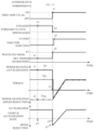
- FIG. 11 is a timing chart illustrating a state of executing the traveling mode switching control as Embodiment 1.
- “Tcl” is a clutch torque transmitted by the forward clutch 24
- “Tpri” is an input torque to the primary pulley 20
- “Tmg” is the motor torque (the power running torque or the power generation torque).
- the power generation-traveling mode of the HEV mode is executed (symbol a 1 ) at time t 11 .
- the forward clutch 24 is controlled to be in the engagement state (symbol b 1 ), the engine torque, or the clutch torque, Tcl is increased (symbol c 1 ), and the motor torque Tmg is increased to the power generation side (symbol d 1 ).
- the forward clutch 24 is controlled to be in the disengagement state (symbol b 3 ) and the traveling mode is switched to the EV mode (symbol a 2 ).
- the injector 42 is controlled to be in a fuel cutoff state (symbol g 1 ).
- the shift period Tt for reduction of the engine torque is set longer.
- the situation where the continuously variable transmission mechanism 22 is controlled to be in the low side is a situation where the engine torque is amplified and transmitted to the rear wheels 19 r , and it is also a situation where blocking of the engine torque associated with the clutch disengagement can easily change the vehicle acceleration rate.
- setting the shift period Tt longer enables a sufficient reduction of the engine torque, reducing the disengagement shock of the forward clutch 24 . This enables switching of the traveling mode without giving a sense of discomfort to the driver of the vehicle 11 .
- the shift period Tt for decreasing the engine torque is set longer.
- the shift period Tt for decreasing the engine torque is set longer as the engine torque becomes larger.
- blocking of the engine torque caused by the clutch disengagement can easily change the vehicle acceleration rate.
- setting the shift period Tt longer can sufficiently reduce the engine torque, and thus reduce the disengagement shock of the forward clutch 24 . This enables switching of the traveling mode without giving a sense of discomfort to the driver of the vehicle 11 .
- the engine torque and the motor torque are controlled so as to keep the vehicle acceleration rate constant, so as to keep the input torque Tpri to the primary pulley 20 constant, but the disclosure is not limited thereto.
- the engine torque and the motor torque may be controlled so as to increase the vehicle acceleration rate, and the engine torque and the motor torque may be controlled so as to decrease the vehicle acceleration rate.
- FIG. 12 is a timing chart illustrating a state of executing traveling mode switching control as Comparative Embodiment.
- the power generation-traveling mode of the HEV mode is executed (symbol a 1 ) at time t 21 .
- the forward clutch 24 is controlled to be in the engagement state (symbol b 1 ), the engine torque, or the clutch torque, Tcl is increased (symbol c 1 ), and the motor torque Tmg is increased to the power generation side (symbol d 1 ).
- the forward clutch 24 is controlled to be in the disengagement state (symbol b 2 ) and the traveling mode is switched to the EV mode (symbol a 2 ).
- the injector 42 is controlled to be in the fuel cutoff state (symbol g 1 ).
- FIG. 13 is a timing chart illustrating a state of executing traveling mode switching control as Embodiment 2.
- the assist mode of the HEV mode is executed at time t 31 (symbol a 1 ). Accordingly, the forward clutch 24 is controlled in the engagement state (symbol b 1 ), the engine torque, or the clutch torque, Tcl is increased (symbol c 1 ), and the motor torque Tmg is increased to the power running side (symbol d 1 ).
- the shift period Tt is also set based on the transmission gear ratio, the vehicle acceleration rate and the engine torque.
- the configuration of the power train 14 is not limited to the configuration illustrated in FIG. 2 , and a power train equipped with a vehicle control apparatus according to the disclosure may have another configuration.
- FIGS. 14 and 15 illustrate other configuration examples of the power train.
- the engine 12 and the rear wheels 19 r are coupled to each other via the power transmission path 30 including a rotation shaft and other components.
- the power transmission path 30 coupling the engine 12 to the rear wheels 19 r includes the forward clutch 24 and the continuously variable transmission mechanism 22 .
- the forward clutch 24 is disposed between the engine 12 and the continuously variable transmission mechanism 22 .
- the secondary shaft 26 forming the power transmission path 30 is coupled to the motor generator 15 via a gear train 80 .
- the motor generator 15 is coupled to the rear wheels 19 r from an output side of the continuously variable transmission mechanism 22 via the power transmission path 30 .
- a vehicle control apparatus according to the disclosure can control an illustrated power train 81 of this type in the same manner as the above-described vehicle control apparatus 10 .
- the engine 12 and the motor generator 15 are coupled to the rear wheels 19 r , but the disclosure is not limited thereto.
- the engine 12 and the motor generator 15 may be coupled to the front wheels 19 r illustrated in FIG. 1 .
- each of the front wheels 19 f may serve as a “first drive wheel” and each of the rear wheels 19 r may serve as a “second drive wheel”.
- the motor generator 15 is coupled to the rear wheels 90 r via a power transmission path 91 .
- the engine 12 is coupled to the front wheels 90 f via a power transmission path 92 composed of a rotation shaft and others.
- each of the rear wheels 90 r may serve as a “first drive wheel”
- each of the front wheels 90 f may serve as a “second drive wheel”.
- the power transmission path 92 for coupling the engine 12 to the front wheels 90 f includes the forward clutch 24 and the continuously variable transmission mechanism 22 .
- the forward clutch 24 on the power transmission path 92 is disposed between the engine 12 and the continuously variable transmission mechanism 22 .
- a power train equipped with a vehicle control apparatus according to the disclosure may have a configuration, in which the engine 12 is coupled to the rear wheels 90 r while the motor generator 15 is coupled to the front wheels 90 f .
- each of the front wheels 90 f may serve as a “first drive wheel” and each of the rear wheels 90 r may serve as a “second drive wheel”.
- a so-called in-wheel motor provided inside a hub of the front wheel 90 f or the rear wheel 90 r may be used as the motor generator 15 .
- control system 60 includes the multiple control units CU 1 to CU 5 , but the disclosure is not limited thereto.
- the control system 60 may use one control unit.
- the continuously variable transmission mechanism 22 including the pulleys 20 and 21 in pairs are used as a transmission mechanism disposed in the power transmission path 30 .
- the transmission mechanism may be an automatic transmission of a planetary gear type or a parallel shaft type.
- the forward clutch 24 may be a friction clutch or a meshing clutch.
- the injector 42 is controlled to be in the fuel cutoff state after the disengagement of the forward clutch 24 .
- the disclosure is not limited thereto, and the injector 42 may be controlled to be in the fuel cutoff state before the disengagement of the forward clutch 24 .
- the engine torque and the motor torque are continuously changed over the shift period Tt, but the disclosure is not limited thereto.
- the engine torque may be decreased and the power running torque of the motor generator 15 may be increased.
- the engine torque can be decreased and the power running torque can be increased under the engagement state of the forward clutch 24 , and thus a shock can be reduced at the time of disengaging the forward clutch 24 . That is, at the time of switching from the HEV mode to the EV mode, the control system 60 allows the engagement of the forward clutch 24 over the shift period Tt. Under the state where the forward clutch 24 is engaged, the control system 60 decreases the torque of the engine 12 and increases the power running torque of the motor generator 15 .
- the shift period Tt is set based on the transmission gear ratio, the vehicle acceleration rate and the engine torque, but the disclosure is not limited thereto.
- the shift period Tt may be set based on the transmission gear ratio alone, the shift period Tt may be set based on the transmission gear ratio and the vehicle acceleration rate, or the shift period Tt may be set based on the transmission gear ratio and the engine torque.
- the shift period Tt may be set based on at least any one of the transmission gear ratio, the vehicle acceleration rate and the engine torque.
- each of time periods T 1 to T 3 forming the shift period Tt is set to be continuously varied.
- each of periods T 1 to T 3 may be set to be discretely varied
- the shift period Tt is calculated by adding up the time periods T 1 to T 3 , but the disclosure is not limited thereto.
- factors may be set based on the transmission gear ratio, the vehicle acceleration rate and the engine torque, and the shift period Tt may be calculated by multiplying a basic period by the factors.
- the vehicle control apparatus controls, upon switching from the first traveling mode to the second traveling mode, the clutch mechanism to be in a state where the clutch mechanism is engaged for an entirety of the shift period, and under the state of the engagement of the clutch mechanism, the vehicle control apparatus decreases the torque of the engine and increases the power running torque of the motor generator. This can reduce a shock at the time of switching of the traveling modes.
Landscapes
- Engineering & Computer Science (AREA)
- Transportation (AREA)
- Mechanical Engineering (AREA)
- Chemical & Material Sciences (AREA)
- Combustion & Propulsion (AREA)
- Automation & Control Theory (AREA)
- Hybrid Electric Vehicles (AREA)
- Electric Propulsion And Braking For Vehicles (AREA)
Abstract
Description
Claims (16)
Applications Claiming Priority (2)
| Application Number | Priority Date | Filing Date | Title |
|---|---|---|---|
| JP2021059528A JP7663396B2 (en) | 2021-03-31 | 2021-03-31 | Vehicle control device |
| JP2021-059528 | 2021-03-31 |
Publications (2)
| Publication Number | Publication Date |
|---|---|
| US20220314962A1 US20220314962A1 (en) | 2022-10-06 |
| US12258003B2 true US12258003B2 (en) | 2025-03-25 |
Family
ID=83405121
Family Applications (1)
| Application Number | Title | Priority Date | Filing Date |
|---|---|---|---|
| US17/692,412 Active 2042-11-28 US12258003B2 (en) | 2021-03-31 | 2022-03-11 | Vehicle control apparatus |
Country Status (3)
| Country | Link |
|---|---|
| US (1) | US12258003B2 (en) |
| JP (1) | JP7663396B2 (en) |
| CN (1) | CN115140057A (en) |
Citations (12)
| Publication number | Priority date | Publication date | Assignee | Title |
|---|---|---|---|---|
| JPH1098804A (en) | 1996-09-24 | 1998-04-14 | Toyota Motor Corp | Drive control device for hybrid vehicle |
| US20050090366A1 (en) | 2003-10-22 | 2005-04-28 | Atsushi Namba | Control device for hybrid vehicle |
| JP2008273460A (en) | 2007-05-02 | 2008-11-13 | Nissan Motor Co Ltd | Drive control apparatus for hybrid vehicle |
| US20120245785A1 (en) | 2009-12-16 | 2012-09-27 | Honda Motor Co., Ltd. | Hybrid vehicle and control method thereof |
| US8550947B2 (en) * | 2010-09-28 | 2013-10-08 | Aisin Aw Co., Ltd. | Transmission apparatus and shift control apparatus |
| JP2014113870A (en) | 2012-12-07 | 2014-06-26 | Toyota Motor Corp | Control device for vehicle |
| US9415767B2 (en) * | 2013-02-07 | 2016-08-16 | Toyota Jidosha Kabushiki Kaisha | Travel control device of hybrid vehicle |
| US20190084553A1 (en) * | 2017-09-21 | 2019-03-21 | Toyota Jidosha Kabushiki Kaisha | Control device of vehicle |
| US10556593B2 (en) * | 2017-12-05 | 2020-02-11 | Toyota Jidosha Kabushiki Kaisha | Series hybrid vehicle |
| US11338795B2 (en) * | 2017-12-27 | 2022-05-24 | Subaru Corporation | Vehicle control apparatus |
| US20220305901A1 (en) * | 2021-03-26 | 2022-09-29 | Subaru Corporation | Vehicle control apparatus |
| US20230391180A1 (en) * | 2022-06-03 | 2023-12-07 | Kawasaki Motors, Ltd. | Drive system of hybrid utility vehicle |
Family Cites Families (1)
| Publication number | Priority date | Publication date | Assignee | Title |
|---|---|---|---|---|
| JP7298179B2 (en) | 2019-02-18 | 2023-06-27 | 日産自動車株式会社 | Electric vehicle control method and electric vehicle drive system |
-
2021
- 2021-03-31 JP JP2021059528A patent/JP7663396B2/en active Active
-
2022
- 2022-03-07 CN CN202210215206.0A patent/CN115140057A/en active Pending
- 2022-03-11 US US17/692,412 patent/US12258003B2/en active Active
Patent Citations (16)
| Publication number | Priority date | Publication date | Assignee | Title |
|---|---|---|---|---|
| JPH1098804A (en) | 1996-09-24 | 1998-04-14 | Toyota Motor Corp | Drive control device for hybrid vehicle |
| US20050090366A1 (en) | 2003-10-22 | 2005-04-28 | Atsushi Namba | Control device for hybrid vehicle |
| JP2005130564A (en) | 2003-10-22 | 2005-05-19 | Fuji Heavy Ind Ltd | Control device for hybrid vehicle |
| JP2008273460A (en) | 2007-05-02 | 2008-11-13 | Nissan Motor Co Ltd | Drive control apparatus for hybrid vehicle |
| US20140249709A1 (en) | 2009-12-16 | 2014-09-04 | Honda Motor Co., Ltd. | Hybrid vehicle and control method thereof |
| US20140025247A1 (en) | 2009-12-16 | 2014-01-23 | Honda Motor Co., Ltd. | Hybrid vehicle and control method thereof |
| US20120245785A1 (en) | 2009-12-16 | 2012-09-27 | Honda Motor Co., Ltd. | Hybrid vehicle and control method thereof |
| JP2014196104A (en) | 2009-12-16 | 2014-10-16 | 本田技研工業株式会社 | Hybrid vehicle and hybrid vehicle control method |
| US8550947B2 (en) * | 2010-09-28 | 2013-10-08 | Aisin Aw Co., Ltd. | Transmission apparatus and shift control apparatus |
| JP2014113870A (en) | 2012-12-07 | 2014-06-26 | Toyota Motor Corp | Control device for vehicle |
| US9415767B2 (en) * | 2013-02-07 | 2016-08-16 | Toyota Jidosha Kabushiki Kaisha | Travel control device of hybrid vehicle |
| US20190084553A1 (en) * | 2017-09-21 | 2019-03-21 | Toyota Jidosha Kabushiki Kaisha | Control device of vehicle |
| US10556593B2 (en) * | 2017-12-05 | 2020-02-11 | Toyota Jidosha Kabushiki Kaisha | Series hybrid vehicle |
| US11338795B2 (en) * | 2017-12-27 | 2022-05-24 | Subaru Corporation | Vehicle control apparatus |
| US20220305901A1 (en) * | 2021-03-26 | 2022-09-29 | Subaru Corporation | Vehicle control apparatus |
| US20230391180A1 (en) * | 2022-06-03 | 2023-12-07 | Kawasaki Motors, Ltd. | Drive system of hybrid utility vehicle |
Non-Patent Citations (1)
| Title |
|---|
| Japanese Office Action issued in Japanese Patent Application No. 2021-059528 dated Dec. 17, 2024, with machine translation. |
Also Published As
| Publication number | Publication date |
|---|---|
| JP2022156035A (en) | 2022-10-14 |
| JP7663396B2 (en) | 2025-04-16 |
| US20220314962A1 (en) | 2022-10-06 |
| CN115140057A (en) | 2022-10-04 |
Similar Documents
| Publication | Publication Date | Title |
|---|---|---|
| KR102018474B1 (en) | How to control the drive of a hybrid car, and hybrid car | |
| US8147366B2 (en) | Power output apparatus and vehicle | |
| US10850600B2 (en) | Drive force control system for hybrid vehicles | |
| US10946853B2 (en) | Drive force control system for hybrid vehicles | |
| JP2017177975A (en) | Hybrid vehicle system | |
| US10124795B2 (en) | Driving force control system for hybrid vehicle | |
| WO2014091588A1 (en) | Control device for hybrid vehicle | |
| EP3030441A1 (en) | Control apparatus and control method for hybrid vehicle | |
| JP6817767B2 (en) | Control device and control method for hybrid vehicle system | |
| US10933862B2 (en) | Vehicle control system | |
| JP2020032918A (en) | Hybrid vehicle | |
| US11511730B2 (en) | Drive device, and vehicle | |
| JP5974888B2 (en) | Vehicle control device | |
| JP2007198439A (en) | Oil pump control device for electric vehicle and electric vehicle equipped with the same | |
| US20220305901A1 (en) | Vehicle control apparatus | |
| JP6863312B2 (en) | Hybrid vehicle control device | |
| US12258003B2 (en) | Vehicle control apparatus | |
| US12005782B2 (en) | Vehicle driving device | |
| CN114802193B (en) | Vehicle control device | |
| JP4253937B2 (en) | Control device for vehicle drive device | |
| US20220063586A1 (en) | Vehicle control system | |
| JP2020152241A (en) | Vehicle control device | |
| JP2008239131A (en) | Hybrid vehicle | |
| WO2026023027A1 (en) | Control device for vehicle | |
| JP2023048071A (en) | Hybrid vehicle control device |
Legal Events
| Date | Code | Title | Description |
|---|---|---|---|
| AS | Assignment |
Owner name: SUBARU CORPORATION, JAPAN Free format text: ASSIGNMENT OF ASSIGNORS INTEREST;ASSIGNORS:OOSAWA, JUN;KOMURO, MASAKI;REEL/FRAME:059236/0867 Effective date: 20220225 |
|
| FEPP | Fee payment procedure |
Free format text: ENTITY STATUS SET TO UNDISCOUNTED (ORIGINAL EVENT CODE: BIG.); ENTITY STATUS OF PATENT OWNER: LARGE ENTITY |
|
| STPP | Information on status: patent application and granting procedure in general |
Free format text: DOCKETED NEW CASE - READY FOR EXAMINATION |
|
| STPP | Information on status: patent application and granting procedure in general |
Free format text: NON FINAL ACTION MAILED |
|
| STPP | Information on status: patent application and granting procedure in general |
Free format text: RESPONSE TO NON-FINAL OFFICE ACTION ENTERED AND FORWARDED TO EXAMINER |
|
| STPP | Information on status: patent application and granting procedure in general |
Free format text: NOTICE OF ALLOWANCE MAILED -- APPLICATION RECEIVED IN OFFICE OF PUBLICATIONS |
|
| ZAAB | Notice of allowance mailed |
Free format text: ORIGINAL CODE: MN/=. |
|
| STPP | Information on status: patent application and granting procedure in general |
Free format text: PUBLICATIONS -- ISSUE FEE PAYMENT VERIFIED |
|
| STCF | Information on status: patent grant |
Free format text: PATENTED CASE |
|
| STPP | Information on status: patent application and granting procedure in general |
Free format text: WITHDRAW FROM ISSUE AWAITING ACTION |
|
| STPP | Information on status: patent application and granting procedure in general |
Free format text: AWAITING TC RESP., ISSUE FEE NOT PAID |
|
| STPP | Information on status: patent application and granting procedure in general |
Free format text: PUBLICATIONS -- ISSUE FEE PAYMENT VERIFIED |
|
| STCF | Information on status: patent grant |
Free format text: PATENTED CASE |