US12216446B2 - Ballbar testing tune-up method for machine tool - Google Patents
Ballbar testing tune-up method for machine tool Download PDFInfo
- Publication number
- US12216446B2 US12216446B2 US17/451,924 US202117451924A US12216446B2 US 12216446 B2 US12216446 B2 US 12216446B2 US 202117451924 A US202117451924 A US 202117451924A US 12216446 B2 US12216446 B2 US 12216446B2
- Authority
- US
- United States
- Prior art keywords
- ballbar
- axis
- parameter
- servo
- controller
- Prior art date
- Legal status (The legal status is an assumption and is not a legal conclusion. Google has not performed a legal analysis and makes no representation as to the accuracy of the status listed.)
- Active, expires
Links
- 238000012360 testing method Methods 0.000 title claims abstract description 70
- 238000000034 method Methods 0.000 title claims abstract description 36
- 230000004044 response Effects 0.000 claims abstract description 19
- 238000005259 measurement Methods 0.000 claims description 27
- 238000005070 sampling Methods 0.000 claims description 7
- 238000001914 filtration Methods 0.000 claims description 5
- 230000003287 optical effect Effects 0.000 claims description 5
- 238000004519 manufacturing process Methods 0.000 abstract description 11
- 238000004364 calculation method Methods 0.000 description 12
- 238000004458 analytical method Methods 0.000 description 4
- 238000002474 experimental method Methods 0.000 description 4
- 238000010586 diagram Methods 0.000 description 3
- 230000000694 effects Effects 0.000 description 3
- 230000008859 change Effects 0.000 description 2
- 238000011161 development Methods 0.000 description 2
- 238000012986 modification Methods 0.000 description 2
- 230000004048 modification Effects 0.000 description 2
- 230000008569 process Effects 0.000 description 2
- 238000012795 verification Methods 0.000 description 2
- 230000001133 acceleration Effects 0.000 description 1
- 230000003044 adaptive effect Effects 0.000 description 1
- 238000006243 chemical reaction Methods 0.000 description 1
- 230000002950 deficient Effects 0.000 description 1
- 238000005516 engineering process Methods 0.000 description 1
- 238000007689 inspection Methods 0.000 description 1
- 238000012545 processing Methods 0.000 description 1
- 238000011160 research Methods 0.000 description 1
Images


Classifications
-
- G—PHYSICS
- G05—CONTROLLING; REGULATING
- G05B—CONTROL OR REGULATING SYSTEMS IN GENERAL; FUNCTIONAL ELEMENTS OF SUCH SYSTEMS; MONITORING OR TESTING ARRANGEMENTS FOR SUCH SYSTEMS OR ELEMENTS
- G05B19/00—Programme-control systems
- G05B19/02—Programme-control systems electric
- G05B19/18—Numerical control [NC], i.e. automatically operating machines, in particular machine tools, e.g. in a manufacturing environment, so as to execute positioning, movement or co-ordinated operations by means of programme data in numerical form
- G05B19/401—Numerical control [NC], i.e. automatically operating machines, in particular machine tools, e.g. in a manufacturing environment, so as to execute positioning, movement or co-ordinated operations by means of programme data in numerical form characterised by control arrangements for measuring, e.g. calibration and initialisation, measuring workpiece for machining purposes
-
- B—PERFORMING OPERATIONS; TRANSPORTING
- B23—MACHINE TOOLS; METAL-WORKING NOT OTHERWISE PROVIDED FOR
- B23Q—DETAILS, COMPONENTS, OR ACCESSORIES FOR MACHINE TOOLS, e.g. ARRANGEMENTS FOR COPYING OR CONTROLLING; MACHINE TOOLS IN GENERAL CHARACTERISED BY THE CONSTRUCTION OF PARTICULAR DETAILS OR COMPONENTS; COMBINATIONS OR ASSOCIATIONS OF METAL-WORKING MACHINES, NOT DIRECTED TO A PARTICULAR RESULT
- B23Q17/00—Arrangements for observing, indicating or measuring on machine tools
- B23Q17/22—Arrangements for observing, indicating or measuring on machine tools for indicating or measuring existing or desired position of tool or work
-
- G—PHYSICS
- G05—CONTROLLING; REGULATING
- G05B—CONTROL OR REGULATING SYSTEMS IN GENERAL; FUNCTIONAL ELEMENTS OF SUCH SYSTEMS; MONITORING OR TESTING ARRANGEMENTS FOR SUCH SYSTEMS OR ELEMENTS
- G05B19/00—Programme-control systems
- G05B19/02—Programme-control systems electric
- G05B19/18—Numerical control [NC], i.e. automatically operating machines, in particular machine tools, e.g. in a manufacturing environment, so as to execute positioning, movement or co-ordinated operations by means of programme data in numerical form
- G05B19/404—Numerical control [NC], i.e. automatically operating machines, in particular machine tools, e.g. in a manufacturing environment, so as to execute positioning, movement or co-ordinated operations by means of programme data in numerical form characterised by control arrangements for compensation, e.g. for backlash, overshoot, tool offset, tool wear, temperature, machine construction errors, load, inertia
Definitions
- the present invention relates to a ballbar testing tune-up method for machine tools, and more particularly to the ballbar testing tune-up method that obtains a phase characteristic and a peak-value characteristic by carrying a ballbar test and obtains a proposed servo parameter by a Lagrange interpolation polynomial, so that the method can be applied to a machine tool system, to improve performance and working precision.
- CNC computer numerical control
- the quick inspection and adjustment of the performance of the CNC machine tools are necessary tasks, and the most popular measuring instrument for machine tools is the Reinshaw double ball bar (DBB) measuring instrument, and a DBB is provided for obtaining the error origin information of the machine, and then operators make a necessary adjustment based on their experience by a trial and error method.
- DBB Reinshaw double ball bar
- the DBB not just incurs a high price only, but also consumes the time and cost for setting up the instrument and calibrating the instrument by a measuring center.
- a ballbar testing tune-up method for machine tool includes the steps of: letting a machine tool system execute a ballbar test; obtaining a phase characteristic and a peak-value characteristic according to the result of the ballbar test; creating a Lagrange interpolation polynomial, increasing an interpolation order thereof according to the number of ballbar tests, and inputting a corresponding servo controller parameter of the machine tool system each time when executing the ballbar test, and at least one of the phase characteristic and the peak-value characteristic; obtaining a proposed servo parameter accordingly; and inputting the proposed servo parameter to the machine tool system.
- the phase characteristic is an average value of the difference between the radius sampled at a position of the X-axis and Y-axis with a contour error fixed cycle in the ballbar test result and an average radius of the ballbar test.
- the peak-value characteristic is the difference of peak values at the X-axis and Y-axis in the ballbar test result.
- the peak-value characteristic is defined by defining a sampling time based on the neighborhood of the peak values of the X-axis and Y-axis and using the sampling time as a filter range to calculate an average value of the peak values to perform a filtering, and using the difference between the peak values of the X-axis and Y-axis after the filtering as the peak-value characteristic.
- the machine tool system includes a servo controller having a position loop, and the proposed servo parameter is inputted as a position controller parameter to the position loop.
- the proposed servo parameter is obtained by inputting the phase characteristic into the Lagrange interpolation polynomial.
- the machine tool system includes a servo controller having a velocity loop, and the proposed servo parameter is inputted as a controller parameter into the position loop.
- the proposed servo parameter is obtained by inputting the phase characteristic and the peak-value characteristic into the Lagrange interpolation polynomial.
- FIG. 1 is a flow chart of the present invention
- FIG. 2 is a key to the arrangement of the partial views of FIG. 2 a and FIG. 2 b.
- FIG. 2 a is a part of a block diagram showing a model of a virtual feed shaft system of the present invention
- FIG. 2 b is another part of a block diagram showing a model of a virtual feed shaft system of the present invention
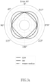
- FIG. 3 a is a polar coordinate graph showing the impact of phase error produced by the present invention, and the phase of Y-axis is ahead of the phase of X-axis;
- FIG. 3 b is a polar coordinate graph showing the impact of phase error produced by the present invention, and the phase of Y-axis is behind the phase of X-axis;
- FIG. 4 a is a polar coordinate graph showing the impact of gain error produced by the present invention, and the gain of Y-axis is greater than the gain of X-axis;
- FIG. 4 b is a polar coordinate graph showing the impact of gain error produced by the present invention, and the gain of Y-axis is smaller than the gain of X-axis;
- FIG. 5 is a polar coordinate graph of a ballbar test before making adjustment in accordance with an empirical embodiment of the present invention
- FIG. 6 is a polar coordinate graph of a ballbar test before making adjustment and turning off a feedforward controller in accordance with an empirical embodiment of the present invention
- FIG. 7 a is a polar coordinate graph of a ballbar test before adjusting a position loop parameter in accordance with an empirical embodiment of the present invention
- FIG. 7 b is a polar coordinate graph of a ballbar test after adjusting a position loop parameter in accordance with an empirical embodiment of the present invention
- FIG. 7 c is a table of DBB measurement results after making adjustment in accordance with an empirical embodiment of the present invention.
- FIG. 7 d is a graph of DBB measurement results after making adjustment in accordance with an empirical embodiment of the present invention.
- FIG. 8 a is a table of DBB measurement results when the feed rate is 1000 mm/min in accordance with an empirical embodiment of the present invention
- FIG. 8 b is a graph of DBB measurement results when the feed rate is 1000 mm/min in accordance with an empirical embodiment of the present invention
- FIG. 8 c is a table of DBB measurement results when the feed rate is 3000 mm/min in accordance with an empirical embodiment of the present invention.
- FIG. 8 d is a graph of DBB measurement results when the feed rate is 3000 mm/min in accordance with an empirical embodiment of the present invention.
- FIG. 8 e is a table of DBB measurement results when the feed rate is 8000 mm/min in accordance with an empirical embodiment of the present invention.
- FIG. 8 f is a graph of DBB measurement results when the feed rate is 8000 mm/min in accordance with an empirical embodiment of the present invention.
- the method includes the following steps:
- the CNC servo loop comprises, a current loop, a velocity loop and a position loop arranged from inside to outside.
- the control block diagram of the model is as shown in FIG. 2 a and FIG.
- K vi and K vp are the parameters of the servo controller
- s is a Laplace operator
- K p is the position loop of the proportional (P) controller
- VF AF are the velocity and acceleration of the feedforward control system
- the modular machine tool system includes loop gains of each shaft, a linear controller, and a feedforward controller; wherein the virtual feed shaft system changes and adjusts the parameters to avoid serious damages to the machine tool system caused by the wrong controller parameters during the experiment and establish a rare single influence phenomenon in a real machine measurement, while effectively eliminating unnecessary influences and greatly reducing the cost of collecting measurement signal sampled. Therefore, the virtual feed shaft system as shown in FIG. 2 a and FIG. 2 b is provided for creating sufficient databases to analyze the influence of servo mismatch.
- the machine tool system executes the ballbar test. Since the servo mismatch comes from a response error between the X-axis and Y-axis of the machine tool system, and the frequency domain analysis can be used to know if there is a change of gain and phase in the system response, so that a ballbar test is executed in accordance with an embodiment of the present invention, and the original equipped optical ruler of the machine tool system is provided to perform the ballbar test.
- Equation 9 r ccw ( t ′)> R ,r cw ( t ′) ⁇ R
- Equation 10 r ccw ( t ′) ⁇ R ,r cw ( t ′)> R )
- the measurement track r(t) will be greater than R , and if the cycle is from
- the measurement track r(t) will be smaller than R ; and if ⁇ K is smaller than zero, the conditions will be opposite as shown in FIG. 4 .
- S 002 analyzing the servo mismatch to find the key impact and then avoiding errors caused by defective data by eliminating the low-impact segments, and calculating the important characteristics of major high-impact measurement segments.
- a phase characteristic and a peak-value characteristic can be obtained according to the ballbar test result.
- the phase characteristic is defined as an important segment of the ballbar test result obtained when X- and Y-axis phases are inconsistent to each other, causing a contour error synchronously outputted in the fixed cycle t′ of the two axes, and the phase characteristic has better significance.
- the phase error shows up, which axis is ahead or behind can be shown immediately.
- ⁇ circumflex over (R) ⁇ When ⁇ circumflex over (R) ⁇ is greater than zero, it indicates that the Y-axis is ahead of X-axis, so that the counterclockwise measured radius is greater than an average radius in the cycle t′; and when ⁇ circumflex over (R) ⁇ is smaller than zero, it indicates that the Y-axis is behind the X-axis, so that the counterclockwise measured radius is smaller than the average radius in the cycle t′.
- ⁇ t is the controller sampling time and N R is the number of characteristic calculations of segment sampling time; so that an average of the differences between the radius of contour errors occurred in the fixed cycle of the X-axis and Y-axis and the average radius of the ballbar test can be calculated according to the following Equations 11 to 13:
- the time domain peak values of the two axes are inconsistent with each other since the gains of the two axes are different, so that when ⁇ K is greater than zero, the motion trajectory in the ballbar test is as shown in FIG. 4 .
- the measured radius track is greater than an average radius.
- the difference between the peak values of the X-axis and Y-axis is used as the peak-value characteristic ⁇ circumflex over (P) ⁇ e .
- N p sampling time is obtained from the neighborhood of the peak value and used as a filter range t f in an embodiment, and the average value is calculated for filtering, and the difference between the peak values of the two axes is used as the peak-value characteristic ⁇ circumflex over (P) ⁇ e .
- p i 2 p i 1 + R 1 ⁇ R max - R min ⁇ ( p i , max g - p i , min g ) [ Equation ⁇ 21 ]
- p i 2 p i 1 - R 1 ⁇ R max - R min ⁇ ( p i , max g - p i , min g ) [ Equation ⁇ 22 ]
- Equation 23 The calculation method after the second circular measurement is as shown in Equation 23:
- Equation 24 The calculation method after the third circular measurement is as shown in Equation 24:
- p i 4 p i 1 ⁇ F 2 ⁇ F 3 ( F 2 - F 3 ) - p i 2 ⁇ F 1 ⁇ F 3 ( F 1 - F 3 ) + p i 3 ⁇ F 1 ⁇ F 2 ( F 1 - F 2 ) ( F 1 - F 2 ) ⁇ ( F 2 - F 3 ) ⁇ ( F 1 - F 3 ) [ Equation ⁇ 24 ]
- the order of the created Lagrange interpolation polynomial increases with the number k of ballbar tests, so that after the n th ballbar test, the calculation of the Lagrange interpolation polynomial is as shown in Equations 30 and 31. Assumed that the selected characteristic is set to zero, the proposed servo parameter is calculated.
- the present invention can input the proposed servo parameter into the machine tool system to adjust the controller parameter, and further improve its manufacturing precision.
- the present invention further provides a servo adjustment method for improve the contour precision of machine tools.
- a ballbar test is used to obtain the track of an optical ruler, and the aforementioned method is used for the key impact measurement segment, and the Lagrange interpolation is used to obtain the proposed servo parameter, and a parameter adjustment stop condition, a position controller parameter (K pp ), and a velocity controller parameter (K vp K vi ) are set to improve the machine response errors.
- K pp has a larger impact on the system phase and gain, so that the characteristic ⁇ circumflex over (R) ⁇ with better convergence and significant phase is selected, and the aforementioned Lagrange interpolation is used to obtain the proposed servo parameter for adjusting the position controller parameter K pp , and the goals are to minimize the phase characteristic to obtain better response performance and improve the servo mismatching issue. Since the phase characteristic ⁇ circumflex over (R) ⁇ uses segment average for the calculation, therefore some gain errors may remain in the final convergence, and the radius measurement segment is symmetrically oriented at 45 degrees, thus leading to the result of ⁇ circumflex over (R) ⁇ being close to zero.
- the gain characteristic ⁇ circumflex over (P) ⁇ e is used in the second stage, and the aforementioned Lagrange interpolation is used to obtain the proposed servo parameter to adjust the velocity controller parameter K vp , and improve the system gain error; and then the velocity controller parameter K vi is adjusted.
- a phase characteristic ⁇ circumflex over (R) ⁇ with better convergence is used as the calculation characteristic and the abovementioned adjustment is made.
- the stop condition of the algorithm is set as follows:
- the proposed servo parameter obtained from the aforementioned method and the created servo system adjustment system are applied to physical machines such as the CHMER three-axis machine tool for the calibration of servo parameters of the physical systems, and the experiment form is shown in the following Table 1, and a Double Ball Bar (DBB) measuring instrument is provided for the measurement verification before and after adjusting the parameter.
- DBB Double Ball Bar
- the feedforward controller Since the feedforward controller will reduce the impact of the parameters to the response of the system, and a wrong feedforward controller parameter will cause system response errors, therefore the feedforward controller does not adjust its parameter.
- the feedforward controller parameter Before making a servo adjustment, the feedforward controller parameter is turned off to reduce the impact to the system response, and then a circular measurement is carried out to draw a polar coordinate image as shown in FIG. 6 , and the machine adjustment is performed according to the adjusting procedure to improve the response matching of the internal loops of the controller.
- the feedforward controller is turned on as shown in FIG. 7 a to FIG. 7 d to perform DBB verification with different feed rates as shown in FIG. 8 a to FIG. 8 f . Since the machine tool system has other errors that impact the roundness. However, we still can see the effect of servo mismatch is close to zero under different feed rates, thereby proving the effectiveness of the present invention.
Landscapes
- Engineering & Computer Science (AREA)
- Human Computer Interaction (AREA)
- Manufacturing & Machinery (AREA)
- Physics & Mathematics (AREA)
- General Physics & Mathematics (AREA)
- Automation & Control Theory (AREA)
- Mechanical Engineering (AREA)
- Numerical Control (AREA)
- Control Of Position Or Direction (AREA)
- Testing Of Balance (AREA)
- Wire Bonding (AREA)
Abstract
Description
-
- 1. An error measuring model adopts the non-contact measurement and uses a laser tracker to perform a ballbar test, and establish a measuring model to improve the limitations of the physical structure of the machine tool during a Double Ball Bar (DBB) measurement, and raise the servo mismatch problem occurred during the process of adjusting the system by a proposed controller parameter obtained from the DBB measurement in order to adjust the system servo mismatch problem.
- 2. Through the frequency domain analysis of control theory, different control structures are used to achieve the multi-axis dynamic matching and single-axis stability, or an adaptive controller or neuro-like compensation controller to improve the control precision of servers and study the impact of non-linear interference to feed systems. The compensation controller is used for compensation to adjust the precision of the machine tool.
-
- 1. The invention can be applied to a built-in optical ruler of a machine tool system directly to obtain the proposed servo parameter quickly when executing the ballbar test without requiring additional equipment, so that the cost of equipment can be reduced significantly. After the proposed servo parameter is obtained, it can be input to the machine tool system to improve the response of the servo system, reduce the manufacturing contour error, and enhance the working precision of the machine tool system.
and
are the vibration models of the work table and base of the machine tool system respectively,
is the linear motor model with non-linear phenomenon (friction, backlash), VF
x=R cos(ωt) [Equation 1]
y=R sin(ωt) [Equation 2]
x=K x ·R cos(ωt+φ x) [Equation 3]
y=K y ·R sin(ωt+φ y) [Equation 4]
r(t)=R√{square root over (K x 2(R cos(ωt+φ x))2 +K y 2(R sin(ωt+<φy))2)} [Equation 5]
Δφ=φy−φx [Equation 6]
ΔK=K y −K x [Equation 7]
r ccw(t′)>
r ccw(t′)<
to
then the measurement track r(t) will be greater than
to
then the measurement track r(t) will be smaller than
to
the measured radius track is greater than an average radius. The difference between the peak values of the X-axis and Y-axis is used as the peak-value characteristic {circumflex over (P)}e. To reduce the impact of machine vibration and signal conversion, Np sampling time is obtained from the neighborhood of the peak value and used as a filter range tf in an embodiment, and the average value is calculated for filtering, and the difference between the peak values of the two axes is used as the peak-value characteristic {circumflex over (P)}e. When {circumflex over (P)}e is greater than zero, it indicates that the gain value of the Y-axis is greater than the gain value of the X-axis; when {circumflex over (P)}e is smaller than zero, it indicates that the gain value of the Y-axis is smaller than the gain value of X-axis; which can be calculated by the following Equations 14 to 17:
f(F i k)=p i k=1,2 . . . ,n [Equation 18]
[p 1 ,p 2 ,p 3 =k pp ,k vp ,k vi] [Equation 19]
[F 1 ,F 2 ]=[{circumflex over (R)},{circumflex over (P)} e] [Equation 20]
a 1 =F 2 F 3 F 4(F 2 −F 3)(F 2 −F 4)(F 3 −F 4) [Equation 26]
a 2 =F 1 F 3 F 4(F 1 −F 3)(F 1 −F 4)(F 3 −F 4) [Equation 27]
a 3 =F 1 F 2 F 4(F 1 −F 2)(F 1 −F 4)(F 2 −F 4) [Equation 28]
a 4 =F 1 F 2 F 3(F 1 −F 2)(F 1 −F 3)(F 2 −F 3) [Equation 29]
-
- 1. Determining the axis with the response behind: To avoid insufficient gain of the two axes occurred during the manufacture performed at a feed rate higher than the measured feed rate caused by a too large decrease of the frequency width of the machine after making the adjustment, it is necessary to determine the phase or gain of which axis falls behind, and adjust the servo parameter of such axis. After the parameter reaches the range of its limits, the servo controller parameter of the other axis is adjusted.
- 2. Turning of the feedforward controller: Since the feedforward controller will have impact on the system response, therefore it is necessary to turn off the feedforward controller first, and then turn on the feedforward controller after the system adjustment has been made, in order to avoid any wrong proposed parameter calculated by the poor servo system adjustment method of the feedforward controller.
-
- 1. Parameter Convergence: If the proposed controller parameter is equal to the control parameter of the previous ballbar test rounded up to an integer, the system is considered to be convergent, and the current adjustment of the servo parameter is completed.
- 2. Achieving the Goal of System Adjustment: The goal of system adjustment is set, and if the roundness after the ballbar test is smaller than 10 μm, then the goal is considered to be adjusted, and the servo system adjustment is completed and in compliance with the industrial system adjustment standards.
- 3. Reaching the parameter adjustment limits: During the process of adjusting physical systems, the system response error is not only due to the impact of the servo controller parameter, but when there is a possibility of having another error source that affects the calculation of the algorithm and results in a proposed control parameter exceeding the proposed range of the parameter. These situations indicate that the adjustment of the machine tool system parameter has reached its limit, so that the value closest to the proposed control parameter is selected from the parameter proposed range as the proposed control parameter.
| TABLE 1 | |||
| Measured Plane | Plain XY | ||
| Measured feed rate | 3000 mm/min | ||
| Measured radius | 100 mm | ||
Claims (6)
Applications Claiming Priority (2)
| Application Number | Priority Date | Filing Date | Title |
|---|---|---|---|
| TW110129167 | 2021-08-06 | ||
| TW110129167A TWI774504B (en) | 2021-08-06 | 2021-08-06 | Ballbar testing tune-up method for machine tool |
Publications (2)
| Publication Number | Publication Date |
|---|---|
| US20230043926A1 US20230043926A1 (en) | 2023-02-09 |
| US12216446B2 true US12216446B2 (en) | 2025-02-04 |
Family
ID=83807296
Family Applications (1)
| Application Number | Title | Priority Date | Filing Date |
|---|---|---|---|
| US17/451,924 Active 2043-05-02 US12216446B2 (en) | 2021-08-06 | 2021-10-22 | Ballbar testing tune-up method for machine tool |
Country Status (2)
| Country | Link |
|---|---|
| US (1) | US12216446B2 (en) |
| TW (1) | TWI774504B (en) |
Families Citing this family (1)
| Publication number | Priority date | Publication date | Assignee | Title |
|---|---|---|---|---|
| CN118276509B (en) * | 2024-06-03 | 2024-10-18 | 成都飞机工业(集团)有限责任公司 | Servo parameter tuning method for improving dynamic accuracy of five-axis machine tool |
Citations (5)
| Publication number | Priority date | Publication date | Assignee | Title |
|---|---|---|---|---|
| US20040098243A1 (en) * | 2002-11-20 | 2004-05-20 | Renishaw Plc. | Simulation and data manipulation |
| US20160236313A1 (en) * | 2015-02-18 | 2016-08-18 | Hexagon Technology Center Gmbh | Method and test assembly for determining machine parameters |
| CN110539020A (en) * | 2019-09-10 | 2019-12-06 | 清华大学 | Precision self-diagnosis method for double five-axis mirror milling machine tool |
| US20210237218A1 (en) * | 2020-01-30 | 2021-08-05 | Industrial Technology Research Institute | Machine tool adjustment method and system thereof |
| US20210324955A1 (en) * | 2020-04-16 | 2021-10-21 | University Of Maryland, Baltimore County | Closed-Loop Control of an Infinitely Variable Transmission |
Family Cites Families (4)
| Publication number | Priority date | Publication date | Assignee | Title |
|---|---|---|---|---|
| JP3234177B2 (en) * | 1997-07-01 | 2001-12-04 | ファナック株式会社 | Position control device |
| TW519504B (en) * | 2001-03-02 | 2003-02-01 | Wei-Tai Lei | 3D errors measurement device and method |
| TW200940244A (en) * | 2008-03-26 | 2009-10-01 | Univ Nat Formosa | System for detecting error of multi-axis processing machine and method thereof |
| WO2010067651A1 (en) * | 2008-12-09 | 2010-06-17 | 三菱電機株式会社 | Machine motion trajectory measuring device, numerically controlled machine tool, and machine motion trajectory measuring method |
-
2021
- 2021-08-06 TW TW110129167A patent/TWI774504B/en active
- 2021-10-22 US US17/451,924 patent/US12216446B2/en active Active
Patent Citations (5)
| Publication number | Priority date | Publication date | Assignee | Title |
|---|---|---|---|---|
| US20040098243A1 (en) * | 2002-11-20 | 2004-05-20 | Renishaw Plc. | Simulation and data manipulation |
| US20160236313A1 (en) * | 2015-02-18 | 2016-08-18 | Hexagon Technology Center Gmbh | Method and test assembly for determining machine parameters |
| CN110539020A (en) * | 2019-09-10 | 2019-12-06 | 清华大学 | Precision self-diagnosis method for double five-axis mirror milling machine tool |
| US20210237218A1 (en) * | 2020-01-30 | 2021-08-05 | Industrial Technology Research Institute | Machine tool adjustment method and system thereof |
| US20210324955A1 (en) * | 2020-04-16 | 2021-10-21 | University Of Maryland, Baltimore County | Closed-Loop Control of an Infinitely Variable Transmission |
Also Published As
| Publication number | Publication date |
|---|---|
| US20230043926A1 (en) | 2023-02-09 |
| TW202306691A (en) | 2023-02-16 |
| TWI774504B (en) | 2022-08-11 |
Similar Documents
| Publication | Publication Date | Title |
|---|---|---|
| Fu et al. | Geometric error contribution modeling and sensitivity evaluating for each axis of five-axis machine tools based on POE theory and transforming differential changes between coordinate frames | |
| CN112558547B (en) | Quick optimization method for geometric error compensation data of translational shaft of five-axis numerical control machine tool | |
| CN110262394B (en) | A Compensation Method for Contour Error in NC Machining | |
| US7130718B2 (en) | Pathcorrection for an industrial robot | |
| Wu et al. | A systematic optimization approach for the calibration of parallel kinematics machine tools by a laser tracker | |
| CN100462677C (en) | Error Compensation System and Method for Three-coordinate Measuring Machine Tool | |
| Slamani et al. | A comparative evaluation of three industrial robots using three reference measuring techniques | |
| CN113334112B (en) | Workpiece alignment methods, devices, and computer storage media for secondary clamping of machine tools | |
| TWI673620B (en) | Simulation method for milling by use of dynamic position error | |
| CN108838563B (en) | A five-axis laser processing equipment RTCP precision compensation method | |
| CN101639681B (en) | Method for optimizing performance parameters of movement mechanism of electronic equipment | |
| CN110181335A (en) | A kind of lathe translation shaft position correlated error discrimination method based on ball bar measurement | |
| CN106363465A (en) | Method for identifying mutual position relationship of horizontally moving shafts and rotating shaft of multi-axis numerically-controlled machine tool | |
| US12216446B2 (en) | Ballbar testing tune-up method for machine tool | |
| CN116339233B (en) | Machine tool error control method and system based on laser interferometer measurement field | |
| CN114488944A (en) | Interpolation-based servo displacement error compensation method | |
| Wu et al. | Intelligent servo tuning of high-speed machine tools using circular test | |
| Zhong et al. | A dynamic two-axis interpolation test with linear and rotary axes in five-axis machine tool | |
| US12386336B2 (en) | Servo control apparatus and servo control method | |
| Duong et al. | Robot Control Using Alternative Trajectories Based on Inverse Errors in the Workspace | |
| KR101525677B1 (en) | Virtual error estimation simulating method for circular test | |
| CN116256186A (en) | A method and system for testing the dynamic performance of a five-axis machine tool | |
| Zhang et al. | Kinematic error compensation of a double swivel head in five-axis abrasive water jet machine tool | |
| Jiang et al. | Evaluation of the dynamic performance for five-axis CNC machine tools based on RTCP | |
| Amacher et al. | Software-based setpoint optimization methods for laser cutting machine tools |
Legal Events
| Date | Code | Title | Description |
|---|---|---|---|
| FEPP | Fee payment procedure |
Free format text: ENTITY STATUS SET TO UNDISCOUNTED (ORIGINAL EVENT CODE: BIG.); ENTITY STATUS OF PATENT OWNER: SMALL ENTITY |
|
| AS | Assignment |
Owner name: NATIONAL YANG MING CHIAO TUNG UNIVERSITY, TAIWAN Free format text: ASSIGNMENT OF ASSIGNORS INTEREST;ASSIGNORS:LEE, CHING-HUNG;WU, SHUN-FU;REEL/FRAME:057916/0543 Effective date: 20210914 |
|
| FEPP | Fee payment procedure |
Free format text: ENTITY STATUS SET TO SMALL (ORIGINAL EVENT CODE: SMAL); ENTITY STATUS OF PATENT OWNER: SMALL ENTITY |
|
| STPP | Information on status: patent application and granting procedure in general |
Free format text: DOCKETED NEW CASE - READY FOR EXAMINATION |
|
| STPP | Information on status: patent application and granting procedure in general |
Free format text: NON FINAL ACTION MAILED |
|
| STPP | Information on status: patent application and granting procedure in general |
Free format text: RESPONSE TO NON-FINAL OFFICE ACTION ENTERED AND FORWARDED TO EXAMINER |
|
| STPP | Information on status: patent application and granting procedure in general |
Free format text: NOTICE OF ALLOWANCE MAILED -- APPLICATION RECEIVED IN OFFICE OF PUBLICATIONS |
|
| STPP | Information on status: patent application and granting procedure in general |
Free format text: PUBLICATIONS -- ISSUE FEE PAYMENT RECEIVED |
|
| STPP | Information on status: patent application and granting procedure in general |
Free format text: PUBLICATIONS -- ISSUE FEE PAYMENT VERIFIED |
|
| STCF | Information on status: patent grant |
Free format text: PATENTED CASE |