US12201227B2 - Product display stand with reduced movement - Google Patents
Product display stand with reduced movement Download PDFInfo
- Publication number
- US12201227B2 US12201227B2 US17/805,359 US202217805359A US12201227B2 US 12201227 B2 US12201227 B2 US 12201227B2 US 202217805359 A US202217805359 A US 202217805359A US 12201227 B2 US12201227 B2 US 12201227B2
- Authority
- US
- United States
- Prior art keywords
- damping
- display
- product
- flange
- post
- Prior art date
- Legal status (The legal status is an assumption and is not a legal conclusion. Google has not performed a legal analysis and makes no representation as to the accuracy of the status listed.)
- Active, expires
Links
- 230000033001 locomotion Effects 0.000 title claims abstract description 61
- 238000013016 damping Methods 0.000 claims abstract description 455
- 239000000463 material Substances 0.000 claims abstract description 162
- 230000010355 oscillation Effects 0.000 claims description 36
- 230000006835 compression Effects 0.000 claims description 17
- 238000007906 compression Methods 0.000 claims description 17
- 239000006260 foam Substances 0.000 claims description 12
- 238000000034 method Methods 0.000 claims description 10
- 230000004044 response Effects 0.000 claims description 6
- 239000000047 product Substances 0.000 description 127
- 239000000853 adhesive Substances 0.000 description 13
- 230000001070 adhesive effect Effects 0.000 description 13
- 230000007246 mechanism Effects 0.000 description 9
- 230000000694 effects Effects 0.000 description 6
- 238000010521 absorption reaction Methods 0.000 description 5
- 229920001200 poly(ethylene-vinyl acetate) Polymers 0.000 description 4
- DQXBYHZEEUGOBF-UHFFFAOYSA-N but-3-enoic acid;ethene Chemical compound C=C.OC(=O)CC=C DQXBYHZEEUGOBF-UHFFFAOYSA-N 0.000 description 3
- 230000003467 diminishing effect Effects 0.000 description 3
- 239000005038 ethylene vinyl acetate Substances 0.000 description 3
- 239000006227 byproduct Substances 0.000 description 2
- 238000009434 installation Methods 0.000 description 2
- 230000004048 modification Effects 0.000 description 2
- 238000012986 modification Methods 0.000 description 2
- 239000007787 solid Substances 0.000 description 2
- 230000008878 coupling Effects 0.000 description 1
- 238000010168 coupling process Methods 0.000 description 1
- 238000005859 coupling reaction Methods 0.000 description 1
- 230000003292 diminished effect Effects 0.000 description 1
- 230000003090 exacerbative effect Effects 0.000 description 1
- 230000014759 maintenance of location Effects 0.000 description 1
- 239000002184 metal Substances 0.000 description 1
- 229920001084 poly(chloroprene) Polymers 0.000 description 1
- 229920000642 polymer Polymers 0.000 description 1
- 230000008569 process Effects 0.000 description 1
- 239000012858 resilient material Substances 0.000 description 1
- 230000000717 retained effect Effects 0.000 description 1
- 230000002441 reversible effect Effects 0.000 description 1
- 229920003051 synthetic elastomer Polymers 0.000 description 1
- 239000005061 synthetic rubber Substances 0.000 description 1
- 238000003466 welding Methods 0.000 description 1
Images


Classifications
-
- A—HUMAN NECESSITIES
- A47—FURNITURE; DOMESTIC ARTICLES OR APPLIANCES; COFFEE MILLS; SPICE MILLS; SUCTION CLEANERS IN GENERAL
- A47F—SPECIAL FURNITURE, FITTINGS, OR ACCESSORIES FOR SHOPS, STOREHOUSES, BARS, RESTAURANTS OR THE LIKE; PAYING COUNTERS
- A47F5/00—Show stands, hangers, or shelves characterised by their constructional features
- A47F5/04—Stands with a central pillar, e.g. tree type
- A47F5/06—Stands with a central pillar, e.g. tree type adjustable
-
- A—HUMAN NECESSITIES
- A47—FURNITURE; DOMESTIC ARTICLES OR APPLIANCES; COFFEE MILLS; SPICE MILLS; SUCTION CLEANERS IN GENERAL
- A47B—TABLES; DESKS; OFFICE FURNITURE; CABINETS; DRAWERS; GENERAL DETAILS OF FURNITURE
- A47B13/00—Details of tables or desks
- A47B13/08—Table tops; Rims therefor
- A47B13/16—Holders for glasses, ashtrays, lamps, candles or the like forming part of tables
-
- F—MECHANICAL ENGINEERING; LIGHTING; HEATING; WEAPONS; BLASTING
- F16—ENGINEERING ELEMENTS AND UNITS; GENERAL MEASURES FOR PRODUCING AND MAINTAINING EFFECTIVE FUNCTIONING OF MACHINES OR INSTALLATIONS; THERMAL INSULATION IN GENERAL
- F16F—SPRINGS; SHOCK-ABSORBERS; MEANS FOR DAMPING VIBRATION
- F16F1/00—Springs
- F16F1/36—Springs made of rubber or other material having high internal friction, e.g. thermoplastic elastomers
- F16F1/42—Springs made of rubber or other material having high internal friction, e.g. thermoplastic elastomers characterised by the mode of stressing
- F16F1/44—Springs made of rubber or other material having high internal friction, e.g. thermoplastic elastomers characterised by the mode of stressing loaded mainly in compression
- F16F1/445—Springs made of rubber or other material having high internal friction, e.g. thermoplastic elastomers characterised by the mode of stressing loaded mainly in compression the spring material being contained in a generally closed space
-
- F—MECHANICAL ENGINEERING; LIGHTING; HEATING; WEAPONS; BLASTING
- F16—ENGINEERING ELEMENTS AND UNITS; GENERAL MEASURES FOR PRODUCING AND MAINTAINING EFFECTIVE FUNCTIONING OF MACHINES OR INSTALLATIONS; THERMAL INSULATION IN GENERAL
- F16F—SPRINGS; SHOCK-ABSORBERS; MEANS FOR DAMPING VIBRATION
- F16F15/00—Suppression of vibrations in systems; Means or arrangements for avoiding or reducing out-of-balance forces, e.g. due to motion
- F16F15/02—Suppression of vibrations of non-rotating, e.g. reciprocating systems; Suppression of vibrations of rotating systems by use of members not moving with the rotating systems
- F16F15/04—Suppression of vibrations of non-rotating, e.g. reciprocating systems; Suppression of vibrations of rotating systems by use of members not moving with the rotating systems using elastic means
- F16F15/08—Suppression of vibrations of non-rotating, e.g. reciprocating systems; Suppression of vibrations of rotating systems by use of members not moving with the rotating systems using elastic means with rubber springs ; with springs made of rubber and metal
-
- F—MECHANICAL ENGINEERING; LIGHTING; HEATING; WEAPONS; BLASTING
- F16—ENGINEERING ELEMENTS AND UNITS; GENERAL MEASURES FOR PRODUCING AND MAINTAINING EFFECTIVE FUNCTIONING OF MACHINES OR INSTALLATIONS; THERMAL INSULATION IN GENERAL
- F16M—FRAMES, CASINGS OR BEDS OF ENGINES, MACHINES OR APPARATUS, NOT SPECIFIC TO ENGINES, MACHINES OR APPARATUS PROVIDED FOR ELSEWHERE; STANDS; SUPPORTS
- F16M11/00—Stands or trestles as supports for apparatus or articles placed thereon ; Stands for scientific apparatus such as gravitational force meters
- F16M11/20—Undercarriages with or without wheels
- F16M11/22—Undercarriages with or without wheels with approximately constant height, e.g. with constant length of column or of legs
-
- F—MECHANICAL ENGINEERING; LIGHTING; HEATING; WEAPONS; BLASTING
- F16—ENGINEERING ELEMENTS AND UNITS; GENERAL MEASURES FOR PRODUCING AND MAINTAINING EFFECTIVE FUNCTIONING OF MACHINES OR INSTALLATIONS; THERMAL INSULATION IN GENERAL
- F16M—FRAMES, CASINGS OR BEDS OF ENGINES, MACHINES OR APPARATUS, NOT SPECIFIC TO ENGINES, MACHINES OR APPARATUS PROVIDED FOR ELSEWHERE; STANDS; SUPPORTS
- F16M13/00—Other supports for positioning apparatus or articles; Means for steadying hand-held apparatus or articles
- F16M13/02—Other supports for positioning apparatus or articles; Means for steadying hand-held apparatus or articles for supporting on, or attaching to, an object, e.g. tree, gate, window-frame, cycle
-
- F—MECHANICAL ENGINEERING; LIGHTING; HEATING; WEAPONS; BLASTING
- F16—ENGINEERING ELEMENTS AND UNITS; GENERAL MEASURES FOR PRODUCING AND MAINTAINING EFFECTIVE FUNCTIONING OF MACHINES OR INSTALLATIONS; THERMAL INSULATION IN GENERAL
- F16F—SPRINGS; SHOCK-ABSORBERS; MEANS FOR DAMPING VIBRATION
- F16F2230/00—Purpose; Design features
- F16F2230/0052—Physically guiding or influencing
- F16F2230/0076—Pivoting
-
- F—MECHANICAL ENGINEERING; LIGHTING; HEATING; WEAPONS; BLASTING
- F16—ENGINEERING ELEMENTS AND UNITS; GENERAL MEASURES FOR PRODUCING AND MAINTAINING EFFECTIVE FUNCTIONING OF MACHINES OR INSTALLATIONS; THERMAL INSULATION IN GENERAL
- F16M—FRAMES, CASINGS OR BEDS OF ENGINES, MACHINES OR APPARATUS, NOT SPECIFIC TO ENGINES, MACHINES OR APPARATUS PROVIDED FOR ELSEWHERE; STANDS; SUPPORTS
- F16M2200/00—Details of stands or supports
- F16M2200/08—Foot or support base
Definitions
- the described embodiments relate generally to product display stands. More particularly, the present embodiments relate to product display stands used in a retail environment.
- Product display stands are used in retail environments, such as retail stores, or at functions displaying products for viewing by potential customers. Such display stands may hold the product above a display surface to allow for a better view of the product, or to keep the display surface free and available for other purposes.
- a product display stand for reducing displayed product movement includes a damping assembly configured to attach to a display platform.
- the damping assembly includes a damping assembly housing configured to attach to the display platform, the damping assembly housing defining a damping chamber; a damping flange disposed within the damping chamber; and damping material disposed between the damping flange and walls of the damping chamber.
- the product display stand also includes a display post fixed to the damping flange, the display post extending from the damping flange to outside of the damping chamber, the display post configured to extend to an opposite side of the display platform and to retain and display a product.
- a product display system for reducing product oscillation includes a display platform defining an opening therethrough, and a display stand.
- the display stand includes a damping assembly disposed below a display platform at the opening, and a display post extending from the damping assembly through the display platform to a position above the display platform, the display post configured to retain a displayed item above the display platform.
- the damping assembly absorbs forces applied to the display post to diminish movement of the display post by transmitting the forces to foam within the damping assembly through compression of the foam.
- a method for reducing movement of a product displayed on a display stand includes, in response to a force applied to the product, transferring the force through a display post to a damping chamber disposed below a display platform; absorbing the force by compressing resilient damping material within the damping chamber using movement of a structure disposed within the damping chamber and fixed to the display post; and repeating the absorbing step until the product is still.
- FIGS. 1 A and 1 B show a schematic view of a product display stand with oscillation of a displayed product.
- FIGS. 2 A and 2 B show a schematic view of a product display stand with reduced oscillation of a displayed product.
- FIG. 3 show a display fixture in a retail environment having several product display stands.
- FIG. 4 shows a schematic sectional view of a display stand system for reducing movement of a displayed product.
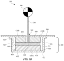
- FIGS. 5 A- 5 D show the display stand system of FIG. 4 operating to reduce movement of a displayed product.
- FIG. 6 A shows a detailed sectional view of a display stand system for reducing movement of a displayed product.
- FIG. 6 B shows an enlarged view of a portion of FIG. 6 A .
- FIG. 6 C shows perspective view of a portion of FIG. 6 B .
- FIG. 7 A shows a detailed sectional view of the display stand system of FIG. 6 A in motion.
- FIG. 7 B shows an enlarged view of a portion of FIG. 7 A
- FIGS. 8 A- 8 D and 9 A- 9 D show arrangements for damping material within a damping assembly of the display stand system.
- FIG. 10 shows a schematic sectional view of a display stand system including damping feet.
- FIGS. 11 A and 11 B show arrangements for the damping feet.
- FIGS. 12 A- 12 E show arrangements for adhesives between components of the damping assembly.
- the following disclosure relates to a product display stand that reduces undesired movement, such as oscillation, in the product being displayed.
- Some stands have long shafts or display posts that support a product vertically above a display platform, like a display fixture in a retail setting for example. If the displayed product experiences a force applied by, for example, a customer pushing the product or bumping the display platform, the display post may flex from side to side, oscillating until the force is dissipated.
- Such oscillation can be of greater magnitude, and last longer, for heavy products (e.g., a laptop or tablet computer) displayed on long, thin posts.
- Such oscillation may be undesirable, because it can interfere with an observer clearly viewing the product, and may make the stand appear less sturdy. It can also put more wear and tear on the stand, reducing its useful life.
- oscillation of a product displayed on a display post is reduced by a damping assembly, which can be a part of the display stand hidden below a display platform, and so out of sight to an observer viewing the displayed product.
- the display post may extend through a hole in the display platform, for example, into a damping chamber of the damping assembly.
- the damping chamber may contain damping material, such as resilient foam, for example.
- the display post may be fixed to a damping flange also positioned within the damping chamber.
- the flange When the display post moves (e.g., because of a force applied to the displayed product), the flange will also move, compressing the damping material, which absorbs some of the force, thus diminishing the motion of the damping flange, the post, and the displayed product. This makes the displayed product return to a stationary position much faster and with less movement than it would otherwise.
- FIG. 1 A shows a display stand system 10 including a display stand post 20 fixed to a display platform 30 supporting a displayed product 50 .
- a force 60 is shown applied to displayed product 50 .
- Force 60 may be applied, for example, directly (e.g., by a customer touching or pushing displayed product 50 ) or indirectly (e.g., by a customer bumping a display fixture of which display platform 30 is a part).
- Force 60 causes movement in displayed product 50 and display stand post 20 , as shown in FIG. 1 B .
- FIG. 1 B illustrates the oscillation that displayed product 50 and display stand post 20 undergo as a result of force 60 .
- Such oscillation will occur back and forth until the applied force is dissipated, at which point displayed product 50 will return to a stationary position (e.g., as shown in FIG. 1 A ).
- Such oscillation can have a high magnitude (i.e., maximum horizontal distance moved), and can take a long time and many oscillations to return to a stationary position.
- the magnitude and time of oscillation can be greater for a heavier displayed product 50 .
- the weight of displayed product 50 can apply torque to display stand post 20 , exacerbating its oscillation.
- FIG. 2 A shows a display stand system 100 including a display stand post 200 extending above a display platform 300 .
- Display stand post 200 is coupled to a damping assembly 400 of display stand system 100 according to some embodiments.
- Display stand post 200 supports a displayed product 500 .
- Force 600 may be applied to displayed product 500 in the same manner as described above for force 60 .
- force 600 causes movement in displayed product 500 and display stand post 200 , as shown in FIG. 2 B .
- damping assembly 400 reduces the oscillation that displayed product 500 and display stand post 200 undergo as a result of force 60 .
- Such oscillation will stop and the applied force will be dissipated through damping assembly 400 much more quickly than in display stand system 10 .
- oscillation of displayed product 500 has a lower magnitude and takes a shorter time and fewer oscillations to return to a stationary position (e.g., as shown in FIG. 2 A ).
- FIG. 3 shows a display fixture 310 forming display platform 300 , with several display stand systems 100 displaying products 500 above display platform 300 .
- such long, thin display stand posts 200 provide a clean, elegant way to display products. They also leave display platform 300 free for other uses.
- Products 500 displayed on such long, thin display stand posts 200 especially heavy products—however could oscillate in the manner described above, which could give an undesirable appearance of motion or instability.
- a damping assembly 400 as described herein reduces such oscillation and returns product 500 to a stationary position faster and with less oscillation than would occur otherwise.
- Such benefits as described are not limited only to long, thin posts, but are in some implementations particularly evident in this context.
- FIG. 4 shows a schematic view with more detail of display stand system 100 .
- display stand system 100 includes a display stand including display post 200 and damping assembly 400 .
- display stand system 100 also includes display platform 300 .
- Display stand system 100 may also include displayed product 500 .
- Damping assembly 400 may be coupled to display platform 300 .
- damping assembly 400 may be attached to an underside of display platform 300 , opposite the side of display platform 300 above which displayed product 500 is displayed.
- Display post 200 may extend from damping assembly 400 through an opening 302 of display platform 300 , to an opposite side of display platform 300 as the side at which damping assembly 400 is coupled. Opening 302 may be slightly larger (e.g., have a greater diameter) than display post 200 to allow for movement of display post 200 .
- damping assembly 400 is not visible from above display platform 300 , thereby effecting its damping without affecting the displayed appearance of display stand system 100 .
- Damping assembly 400 may be removably coupled to display platform 300 (e.g., using bolts, screws, or other removable fastener) or it may be permanently affixed to display platform 300 (e.g., using a permanent adhesive or other permanent fastening technique).
- damping assembly 400 includes a damping assembly housing 410 forming a damping chamber 420 .
- Damping chamber 420 houses damping material 430 and a damping flange 440 .
- Damping assembly 400 may be coupled to display platform 300 via a connection between damping assembly housing 410 and display platform 300 .
- Damping chamber 420 within damping assembly housing 410 may be defined by a bottom surface 422 , a top surface 424 , and one or more side surfaces 426 .
- bottom surface 422 is formed by bottom wall 412 of damping assembly housing 410
- top surface 424 is formed by display platform 300
- side surface 426 is formed by side wall 416 of damping assembly housing 410 .
- other structure may define damping chamber 420 .
- damping assembly 400 may have an upper wall that forms top surface 424 , or there may be intermediate elements between damping assembly housing 410 and/or display platform 300 and damping chamber 420 that define damping chamber 420 .
- damping chamber 420 is closed, as shown in FIG. 4 .
- damping chamber may be more open, for example without side surfaces, and/or with openings through its surfaces.
- damping flange 440 is positioned vertically between solid damping material units 430 .
- a first damping material unit 430 A e.g., an upper damping material unit
- a second damping flange is disposed above and in contact with damping flange 440 .
- Display stand system 100 is shown as a schematic section view in FIG. 4 .
- Display stand system 100 may have rotational symmetry about product display post 200 , such that the portions of a second damping material unit 430 B (e.g., a lower damping material unit) are portions of the same continuous damping material unit, having an annular shape in plan view.
- first damping material unit 430 A may have a circular or annular shape in plan view
- flange 440 may have a circular shape in plan view.
- Such circular shapes can allow damping assembly 400 to dampen oscillation in any direction. However, other shapes may be used for various reasons, including to tailor the degree or direction of oscillation while damping.
- Damping material 430 may be a compressible, resilient material.
- damping material 430 is a solid, resilient foam (e.g., EVA (ethylene-vinyl acetate) foam, PEVA (poly-ethylene-vinyl acetate) foam) or foam-like material (e.g., synthetic rubber such as neoprene).
- EVA ethylene-vinyl acetate
- PEVA poly-ethylene-vinyl acetate
- foam-like material e.g., synthetic rubber such as neoprene
- damping material 430 is more compressible and flexible than the material from which damping flange 440 is formed. Damping flange 440 is rigid and inflexible.
- damping flange 440 is sandwiched between damping material units 430 , which hold damping flange 440 in place within damping chamber 420 .
- damping flange 440 is not directly attached to display platform 300 , but is only indirectly attached through its retention within damping chamber 420 .
- damping flange 440 is not coupled to damping assembly 400 except through contact with damping material 430 . This can help isolate movement of damping flange 440 from display platform 300 for more effective absorption of energy by damping material 430 .
- Damping flange 440 extends horizontally in a width direction between damping material units 430 .
- Product display post 200 is fixed to damping flange 440 .
- a connection 442 between damping flange 440 and product display post 200 does not allow for relative motion between damping flange 440 and product display post 200 at connection 442 in normal use (i.e., connection 442 is a rigid connection).
- damping flange 440 is fixed to product display post 200 by a reversible mechanical connection such as a bolt or collet mechanism.
- damping flange 440 is permanently coupled to product display post 200 (e.g., by welding), and in some embodiments damping flange 440 is unitary with product display post 200 .
- a motion e.g., a horizontal motion
- a force 600 applied to displayed product 500 or product display post 200 will cause a tendency toward corresponding perpendicular motion (e.g., vertical motion) at ends of damping flange 440 , shown in FIG. 5 B .
- FIG. 5 B motion of displayed product 500 in a first horizontal direction (left in FIG.
- damping material 430 sandwiches damping flange 440 within damping chamber 420 , such vertical motion serves to compress damping material 430 , thereby absorbing some of the force caused by the oscillation of displayed product 500 , thereby counteracting and diminishing the oscillation (e.g., in terms of amplitude and time).
- product display post 200 is at least 50 times longer than an average diameter of display post (e.g., at least 100 times longer).
- displayed product 500 may overshoot its stationary position (e.g., centered over post 200 ) and move toward a maximum extent of motion in the opposing direction (see FIG. 5 C ). Due to the absorption of force by damping material 430 described with reference to FIG. 5 B , the maximum extent of motion in the second horizontal direction (shown in FIG. 5 C ) is diminished relative to the maximum extent of motion in the first horizontal direction (shown in FIG. 5 B ). This is represented by the decrease in an angle ⁇ of deviation from a stationary position.
- Damping flange 440 and damping material 430 may operate similarly in response to the horizontal motion of displayed product 500 in the second horizontal direction as described above for the first horizontal direction, just compressing damping material 430 on opposing sides, as shown in FIG. 5 C . This process may repeat back and forth, diminishing oscillation of product 500 each time until product 500 (and the rest of product display system 100 ) are stationary as shown in FIG. 5 D .
- display stand system 100 provides a method for reducing movement of displayed product 500 displayed on product display post 200 .
- the force is transferred through display post 200 to damping chamber 420 disposed below display platform 300 .
- the force is absorbed by compressing resilient damping material 430 within damping chamber 420 using movement of a structure disposed within damping chamber 420 (e.g., damping flange 440 ) and fixed to product display post 200 .
- Such absorption by compression repeats—at alternating positions of the damping material 430 —until displayed product 500 is still.
- such repeating absorption by compression involves first compressing a first portion of damping material 430 (e.g., portion 432 ) and simultaneously compressing a second portion of the damping material 430 (e.g., portion 434 ), the second portion being compressed in a direction parallel to and opposite of the direction in which the first portion is compressed.
- Such repeating absorption by compression involves compressing a third portion of damping material 430 and simultaneously compressing a fourth portion of damping material 430 , the fourth portion being compressed in a direction parallel to and opposite of the direction in which the third portion is compressed.
- a total height of damping material 430 (e.g., damping material units 430 A and 430 B together) in and damping flange 440 together is equal to a total height of damping chamber 420 . In some embodiments this is the case when damping material is unloaded (i.e., not undergoing compression from damping assembly 400 ).
- damping material 430 may be pre-loaded within damping chamber 420 .
- damping material 430 may be compressed (relative to a free state) within damping chamber 420 , by walls of damping chamber 420 .
- damping material unit 430 A may be compressed between damping flange 440 and bottom surface 422 of damping chamber 420
- damping material unit 430 B may be compressed between damping flange 440 and top surface 424 of damping chamber 420 .
- a total height of damping material 430 (e.g., damping material units 430 A and 430 B together) in an unloaded configuration and damping flange 440 together may be greater than a total height of damping chamber 420 .
- damping chamber 420 to compress damping material 430 against damping flange 440 within damping chamber 420 .
- This helps keep damping flange 440 and product display post 200 stationary and not prone to wobbling. It also improves the effectiveness of damping material 430 in absorbing and dissipating forces and associated oscillation of displayed product 500 .
- FIGS. 6 A- 6 C, 7 A, and 7 B show product display stand system 100 in more detail.
- FIGS. 6 A and 6 B are central cross-sectional views and correspond to a state of display stand system 100 in which displayed product 500 is stationary, like in FIG. 5 D , discussed above.
- FIGS. 7 A and 7 B are also central cross-sectional views (taken at the same plane as FIGS. 6 A and 6 B ) and correspond to a state of display stand system 100 in which displayed product 500 is in motion (e.g., oscillating), like in FIGS. 5 B and 5 C , discussed above.
- the description relating to FIGS. 5 A- 5 D above applies to display stand system 100 as shown in FIGS. 6 A- 6 C, 7 A, and 7 B .
- the description relating to FIGS. 6 A- 6 C, 7 A, and 7 B applies to display stand system 100 as shown in FIGS. 5 A- 5 D .
- FIG. 6 A shows display stand system 100
- FIG. 6 B shows an enlarged view of a lower portion of display stand system 100
- FIG. 6 C shows an enlarged lower perspective view of certain parts of display stand system 100 .
- damping assembly housing 410 may be coupled to display platform 300 .
- damping assembly housing 410 may be coupled to an underside of display platform 300 via fasteners 450 (e.g., bolts 450 ) passed through openings 414 in damping assembly housing 410 and threaded into receptacles 332 (e.g., threaded inserts 332 ) of display platform 300 .
- display platform 300 may be formed of an upper layer 320 and a lower layer 330 .
- fastening mechanisms for fastening damping assembly housing 410 to the underside of display platform 300 may only extend into lower layer 330 (or at least not above the top surface of display platform 300 or upper layer 320 ).
- damping assembly housing 410 may be coupled to display platform 300 using other mechanisms such as, for example, other mechanical fasteners or coupling mechanisms or adhesive.
- damping assembly housing 410 includes a lower opening 418 .
- Opening 418 may be accessible from an exterior of damping assembly 400 when damping assembly is installed and coupled to display platform 300 . Opening 418 may be centered in bottom wall 412 of damping assembly housing 410 .
- a lower end of product display post 200 may be accessible through opening 418 . This can enable a user to service or make changes to display stand system 100 while it is still installed.
- product display post 200 can be coupled to or decoupled from damping flange 440 through opening 418 , or the height or rotation of product display post can be adjusted.
- bottom surface 422 of damping chamber extends around the periphery of opening 418 , with damping material 430 and portions of damping flange 440 disposed above it as described above and shown, for example, in FIG. 6 B .
- Damping flange 440 may have a maximum width (e.g., diameter) that is less than an interior width of damping chamber 420 such that it fits inside damping chamber 420 without touching side surfaces 426 of damping chamber 420 .
- damping flange 440 has a maximum width (e.g., diameter) that is greater than a width (e.g., diameter) of opening 418 , such that it cannot fit through opening 418 .
- damping flange 440 and damping material 430 remain in the stacked arrangement described above and shown in FIG. 6 B (e.g., sandwiched together with damping material 430 arranged above and below damping flange 440 and in contact with interior surfaces of damping chamber 420 ).
- Damping flange 440 may include an attachment mechanism 444 for attaching to product display post 200 , which acts as connection 442 to fix damping flange 440 to display post 200 as described above.
- attachment mechanism 444 is a collet that receives product display post 200 and is tightened around and fixed to display post 200 by collet nut 446 .
- damping flange 440 may include a hole 448 therethrough (e.g., centered, as shown in FIG. 6 B ) through which display stand post 200 can pass to reach attachment mechanism 444 .
- product display post 200 may be coupled to display flange in other manners as described above.
- product display post 200 may be fixed to damping flange by a threaded connection (e.g., a threaded end of display post 200 may be received by a threaded hole of damping flange 440 ), a weld, or other connection mechanism.
- damping flange may have a protruding portion 441 extending downward and through opening 418 such that the entirety of damping flange is not disposed within damping chamber 420 .
- Protruding portion 441 may have a shape corresponding to a shape of opening 418 but slightly smaller, so that protruding portion 441 can protrude through opening 418 .
- a minimum distance between protruding portion 441 and a side of opening 418 is less than a minimum distance between an end of damping flange 440 and an interior side surface 426 of damping chamber 420 , which can help prevent damping flange 440 from contacting interior side surface 426 within damping chamber 420 .
- Damping material 430 can take a variety of configurations, as will be explained in more detail below.
- damping material 430 is formed of two damping material units 430 : first damping material unit 430 A disposed beneath damping flange 440 , and second damping material unit 430 B disposed above damping flange.
- both damping material unit 430 A and damping material unit 430 B are annular, forming a ring shape (seen in cross-section in FIG. 6 A and FIG. 6 B ).
- damping material 430 may be a resilient foam or foam-like material.
- damping assembly 400 includes a damping leveler plate 402 disposed between bottom wall 412 of damping assembly housing 410 and first damping material unit 430 A.
- Damping leveler plate 402 may be a rigid flat element (e.g., metal or a hard polymer) and in embodiments in which it is included damping leveler plate 402 may form an interior surface of damping chamber 420 (e.g., bottom surface 422 ).
- Damping leveler plate may be supported on bottom wall 412 directly or via leveler posts 404 (e.g., adjustment screws, such as set screws) that can be adjusted up or down relative to bottom wall 412 to thereby adjust the angle at which damping flange 440 rests within damping chamber 420 . This can allow the angle of product display post 200 to be adjusted if needed (e.g., to make sure that its stationary position is vertical).
- FIGS. 7 A and 7 B show display stand system 100 in an active state, where displayed product 500 is in motion (e.g., oscillating), swaying above display platform 300 , with product display post 200 moving (e.g., flexing, tilting, or both flexing and tilting) away from a stationary vertical position by an angle ⁇ .
- damping flange 440 tilts in response to the movement of product display post 200 and compresses portions of damping material 430 above and below damping flange 440 on opposite sides of product display post 200 .
- damping material 430 below damping flange 440 is compressed (at area 432 in FIG. 7 B ) by damping flange 440 on the same side of damping assembly 400 as the direction in which product display post 200 is tilted away from vertical (the left side in FIG. 7 B ) and a second portion of damping material 430 above damping flange 440 is compressed (at area 434 in FIG. 7 B ) by damping flange 440 on the side of damping assembly 400 positioned away from the direction in which product display post 200 is tilted (the right side in FIG. 7 B ).
- damping material 430 absorbs energy from flange 440 , slowing its motion for its next oscillation.
- damping material 430 may have a high damping coefficient.
- Damping material 430 may be selected for its damping characteristics such as, for example, damping coefficient, rebound control rate, resiliency, to suit the characteristics of a particular implementation, taking account of characteristics such as displayed product 500 weight, product display post 200 length and flexibility, and height of the space in which damping material 430 is to be disposed.
- FIGS. 8 A- 8 D show different potential configurations for damping material 430 within damping chamber 420 .
- FIG. 8 A shows damping material element 430 having an annular configuration about a central axis 428 (coinciding with the position of product display post 200 ), like in FIGS. 6 B and 7 B .
- FIGS. 8 B- 8 D show alternative configurations, including an evenly-segmented arrangement with linear gaps ( FIG. 8 B ), a configuration of small, discrete pads ( FIG. 8 C ), and a cross configuration with small, discrete pads ( FIG. 8 D ).
- the uniform configuration of FIG. 8 A may help control oscillation evenly in any direction, while the arrangements of FIGS. 8 B- 8 D may help control the direction of oscillation by arranging damping material 430 and gaps therebetween.
- FIGS. 9 A- 9 D show different potential configurations for damping material 430 C and damping material 430 D within damping chamber 420 .
- Damping material 430 C is different from damping material 430 D in at least its type (e.g., different type of foam), damping characteristics (e.g., different damping coefficient, rebound control rate, and/or resiliency), or thicknesses.
- the arrangements of FIGS. 9 A- 9 D may help control the direction or degree of oscillation by arranging damping material 430 C, damping material 430 D, and gaps therebetween.
- the damping material arrangements of FIGS. 8 A- 9 D in some embodiments are applied at both an upper side of damping flange 440 within damping chamber 420 and a lower side of damping flange 440 within damping chamber 420 .
- the upper and the lower side have the same arrangement (e.g., the same of one of the arrangements shown in FIGS. 8 A- 9 D or another arrangement), in some embodiments they have different arrangements (e.g., different ones of the arrangements shown in FIGS. 8 A- 9 D or another arrangement).
- damping material 430 may be stacked in layers (e.g., multiple layers of damping material 430 disposed to one side (i.e., above or below) of damping flange 440 between damping flange 440 and an interior surface of damping chamber 420 .
- Such stacked layers may have the same arrangement but different material qualities (e.g., a different material and/or different damping coefficient, rebound control rate, and/or resiliency), or they may have different arrangements with different material qualities.
- the damping material selection and arrangement can be customized help allow the desired damping effect of display stand system, according to its expected environment (e.g., displayed product 500 weight, product display post 200 height, environment of installation and expected forces to be encountered).
- damping material 430 may be pre-loaded. That is, even in a stationary position of display stand system 100 , with displayed product 500 evenly balanced and supported by product display post 200 , damping material 430 may be compressed relative to its free, unloaded state. This compression can be caused by pressing together damping material 430 and flange 440 within damping chamber 420 (e.g., damping material 430 may be pre-loaded by being compressed in the vertical direction in fit within a vertical dimension of damping chamber 420 ).
- damping material 430 In such a pre-loaded state, the resilience of damping material 430 will press against damping flange 440 (e.g., from above and from below) to help stabilize it and keep it in a stationary position (e.g., with displayed product 500 evenly balanced and supported above by product display post 200 ). In some embodiments, such upward and downward pressure from damping material 430 will be applied radially around product display post 200 due to damping material 430 being positioned radially around product display post.
- damping flange 440 may have damping feet 445 extending from a main body 447 (e.g., a main plate 447 ) of damping flange 440 .
- Main body 447 may be flat (e.g., have flat upper and lower surfaces).
- Damping feet 445 may be interposed between main plate 447 and damping material 430 . Damping feet may have a diameter much smaller than a diameter of main plate 447 .
- a damping foot 445 may have a maximum width (e.g., diameter) that is less than 1/10 a maximum width (e.g., diameter) of main plate 447 .
- damping feet 445 are cylindrical (like damping flange 440 in some embodiments), but can have other shapes. Damping feet 445 may compress damping material 430 in a concentrated manner focused at the positions of damping feet 445 , pre-loading damping material 430 in a similar way as discussed above, except that such pre-loading is concentrated at the positions of feet 445 .
- feet 445 are distributed radially about a center of main plate 447 (e.g., about the position at which product display post 200 connects to display flange 440 , at connection 442 between product display post 200 and main plate 447 ).
- FIGS. 11 A and 11 B show views that can represent both top and bottom sides of display flange 440 with feet 445 .
- four feet 445 can be distributed evenly about central axis 428 .
- three feet can be distributed evenly about central axis 428 .
- the upper and the lower sides of flange 440 have the same arrangement of feet 445 (e.g., the same of one of the arrangements shown in FIG. 11 A or 11 B or another arrangement), in some embodiments they have different arrangements (e.g., different ones of the arrangements shown in FIG. 11 A or 11 B or another arrangement).
- display stand system 100 can effect a two-stage damping when displayed product 500 moves (e.g., oscillates) above display platform 300 .
- the first stage is compression of damping material 430 by damping feet 445 .
- the second stage is compression of damping material 430 by main body 447 , which presses against damping material 430 after or to a lesser degree than feet 445 .
- damping flange 440 tilts to one side, and damping feet 445 extend deeper into damping material 430 , driving greater compression and encountering greater resistance due to the resilience of damping material 430 . This is the first stage.
- damping flange 440 tilts more, main body 447 of damping flange 440 compresses damping material 430 , though not as deeply as at damping feet 445 , providing a softer, wider resistance by pressing more shallowly against a greater area of damping material 430 . This is the second stage.
- the first stage can be useful for quickly absorbing energy and thereby reducing motion below a threshold magnitude, while the second stage can be useful for absorbing energy and thereby reducing motion above the threshold, thereby bringing it down beneath the threshold so that it can be absorbed by the first stage.
- the first stage focuses compression more deeply in a concentrated area, while the second stage spreads compression more widely and shallowly.
- This two-stage damping arrangement helps to bring even relatively larger forces and movement down quickly, by allowing the second stage to engage and dampen relatively larger forces and relatively smaller forces in different ways, allowing the damping effect of display stand system 100 to be tailored to most effectively absorb energy and reduce oscillation according to its expected environment (e.g., displayed product 500 weight, product display post 200 height, environment of installation and expected forces to be encountered).
- damping flange 440 and damping material 430 are retained in position relative to each other simply by their constricted motion due to being contained within damping chamber 420 .
- damping material 430 is pre-loaded, forces between damping material 430 , damping flange 440 , and damping assembly housing 410 due to the compression of damping material 430 can help maintain their relative positions.
- an adhesive 438 may be applied between damping material 430 and other portions of damping assembly 400 (e.g., between damping material 430 and damping flange 440 , and/or between damping material 430 and surfaces defining damping chamber 420 ).
- FIGS. 12 A- 12 E show some example configurations of adhesive 438 relative to damping flange 440 .
- FIGS. 12 A- 12 E show views that can represent both top and bottom sides of display flange 440 .
- Such adhesive example configurations may also be applied between damping material 430 and surfaces defining damping chamber 420 .
- FIG. 12 A shows no adhesive being used.
- FIG. 12 B shows adhesive 438 radially branching out from central axis 428 .
- FIGS. 12 C and 12 D show adhesive circles evenly radially spaced about central axis 428 .
- the circles of FIG. 12 C are all the same size.
- the circles of FIG. 12 D are also all the same size, but smaller than those of FIG. 12 C .
- FIG. 12 E shows a single circle adhesive 438 centered on central axis 428 .
- Such adhesive 438 may be applied to ends of feet 445 in embodiments in which feet 445 are used.
- the adhesive configurations of FIGS. 12 A- 12 E may be interposed between damping material 430 and another element, to help fix the adhered elements together and retain their relative positions.
- damping material 430 and damping flange 440 can be disposed between damping material 430 and damping flange 440 , between damping material 430 and interior surfaces of damping chamber 420 , between different layers of damping material 430 , or any combination thereof.
- adhesive 438 between different elements can have the same arrangement, in the same or different orientation about central axis 428 , (e.g., the same of one of the arrangements shown in FIGS. 12 A- 12 E or another arrangement). In some embodiments they have different arrangements (e.g., different ones of the arrangements shown in FIGS. 12 A- 12 B or another arrangement).
- personally identifiable information should follow privacy policies and practices that are generally recognized as meeting or exceeding industry or governmental requirements for maintaining the privacy of users.
- personally identifiable information data should be managed and handled so as to minimize risks of unintentional or unauthorized access or use, and the nature of authorized use should be clearly indicated to users.
Landscapes
- Engineering & Computer Science (AREA)
- General Engineering & Computer Science (AREA)
- Mechanical Engineering (AREA)
- Physics & Mathematics (AREA)
- Acoustics & Sound (AREA)
- Aviation & Aerospace Engineering (AREA)
- Health & Medical Sciences (AREA)
- Child & Adolescent Psychology (AREA)
- Chemical & Material Sciences (AREA)
- Combustion & Propulsion (AREA)
- Vibration Prevention Devices (AREA)
Abstract
Description
Claims (27)
Priority Applications (1)
| Application Number | Priority Date | Filing Date | Title |
|---|---|---|---|
| US17/805,359 US12201227B2 (en) | 2022-06-03 | 2022-06-03 | Product display stand with reduced movement |
Applications Claiming Priority (1)
| Application Number | Priority Date | Filing Date | Title |
|---|---|---|---|
| US17/805,359 US12201227B2 (en) | 2022-06-03 | 2022-06-03 | Product display stand with reduced movement |
Publications (2)
| Publication Number | Publication Date |
|---|---|
| US20230389723A1 US20230389723A1 (en) | 2023-12-07 |
| US12201227B2 true US12201227B2 (en) | 2025-01-21 |
Family
ID=88977608
Family Applications (1)
| Application Number | Title | Priority Date | Filing Date |
|---|---|---|---|
| US17/805,359 Active 2042-08-30 US12201227B2 (en) | 2022-06-03 | 2022-06-03 | Product display stand with reduced movement |
Country Status (1)
| Country | Link |
|---|---|
| US (1) | US12201227B2 (en) |
Citations (8)
| Publication number | Priority date | Publication date | Assignee | Title |
|---|---|---|---|---|
| US4923164A (en) * | 1988-09-19 | 1990-05-08 | Stenberg Richard A | Post support and anchor |
| US8444343B2 (en) * | 2011-05-27 | 2013-05-21 | Mccue Corporation | Impact-absorbing anchoring assembly for protective barrier |
| US20160273175A1 (en) * | 2013-03-13 | 2016-09-22 | Energy Absorption Systems, Inc. | Self-righting flexible delineator with protective collar and method thereof |
| US20180051764A1 (en) * | 2015-03-20 | 2018-02-22 | Oiles Corporation | Seismic base isolation support apparatus |
| US10077535B2 (en) * | 2015-04-24 | 2018-09-18 | Mccue Corporation | Sign post assembly with impact absorbing mechanism |
| US10184261B2 (en) * | 2015-05-07 | 2019-01-22 | Visiontron Corporation | Stanchion or post with a spring-loaded assembly |
| US10568449B1 (en) * | 2019-08-14 | 2020-02-25 | Premises Innovations Llc | Self-rightening post system |
| US11136735B2 (en) * | 2019-02-21 | 2021-10-05 | Slow Stop Guarding Systems, LLC | Impact-resistant and energy-absorbing bollard system |
-
2022
- 2022-06-03 US US17/805,359 patent/US12201227B2/en active Active
Patent Citations (8)
| Publication number | Priority date | Publication date | Assignee | Title |
|---|---|---|---|---|
| US4923164A (en) * | 1988-09-19 | 1990-05-08 | Stenberg Richard A | Post support and anchor |
| US8444343B2 (en) * | 2011-05-27 | 2013-05-21 | Mccue Corporation | Impact-absorbing anchoring assembly for protective barrier |
| US20160273175A1 (en) * | 2013-03-13 | 2016-09-22 | Energy Absorption Systems, Inc. | Self-righting flexible delineator with protective collar and method thereof |
| US20180051764A1 (en) * | 2015-03-20 | 2018-02-22 | Oiles Corporation | Seismic base isolation support apparatus |
| US10077535B2 (en) * | 2015-04-24 | 2018-09-18 | Mccue Corporation | Sign post assembly with impact absorbing mechanism |
| US10184261B2 (en) * | 2015-05-07 | 2019-01-22 | Visiontron Corporation | Stanchion or post with a spring-loaded assembly |
| US11136735B2 (en) * | 2019-02-21 | 2021-10-05 | Slow Stop Guarding Systems, LLC | Impact-resistant and energy-absorbing bollard system |
| US10568449B1 (en) * | 2019-08-14 | 2020-02-25 | Premises Innovations Llc | Self-rightening post system |
Also Published As
| Publication number | Publication date |
|---|---|
| US20230389723A1 (en) | 2023-12-07 |
Similar Documents
| Publication | Publication Date | Title |
|---|---|---|
| US6000670A (en) | Foot structure for apparatus | |
| US8201784B2 (en) | Display device with height-adjustment assembly having spring member | |
| US5867951A (en) | Seismic isolation sliding bearing for structure | |
| US6938869B2 (en) | Plastic pedestal with a height adjustment function | |
| JPH03234945A (en) | Vibration damper | |
| CN105587975A (en) | Foot of a device, in particular of a table-top kitchen appliance | |
| US20090001238A1 (en) | Tilt and swivel mounting for monitors and other devices | |
| JPH10311369A (en) | Base isolation device | |
| KR20130038214A (en) | Methods and compositions for isolating a payload from vibration | |
| US12201227B2 (en) | Product display stand with reduced movement | |
| JP2000352113A (en) | Vibration controlling structure of bolt joint section | |
| US20060039128A1 (en) | Structure for hanging an electronic device | |
| US20210160451A1 (en) | Display device | |
| JPH0254040A (en) | Vibration-free device and response control structure | |
| JP2006336815A (en) | Base isolation device | |
| JP2008513846A (en) | Angle adjustment device for display equipment | |
| CN107110280A (en) | Exempt to shake support meanss | |
| US7278623B2 (en) | Vibration control unit and vibration control body | |
| JP2002039244A (en) | Coned disc spring unit with damping force regulating function | |
| US20090032668A1 (en) | Adjustably-tiltable supporting apparatus and display with the same | |
| JPH1130278A (en) | Base isolation construction | |
| KR100833628B1 (en) | Display device angle adjuster | |
| WO2000031436A1 (en) | Seismic isolation device | |
| JP3131271B2 (en) | Anti-vibration bearing | |
| JP3556910B2 (en) | Seismic isolation device |
Legal Events
| Date | Code | Title | Description |
|---|---|---|---|
| FEPP | Fee payment procedure |
Free format text: ENTITY STATUS SET TO UNDISCOUNTED (ORIGINAL EVENT CODE: BIG.); ENTITY STATUS OF PATENT OWNER: LARGE ENTITY |
|
| AS | Assignment |
Owner name: APPLE INC., CALIFORNIA Free format text: ASSIGNMENT OF ASSIGNORS INTEREST;ASSIGNORS:WANG, ERIC WEIJIA;RITTER, GREGORY R.;ADAMS, JOSHUA;AND OTHERS;SIGNING DATES FROM 20220721 TO 20220727;REEL/FRAME:060753/0029 |
|
| STPP | Information on status: patent application and granting procedure in general |
Free format text: DOCKETED NEW CASE - READY FOR EXAMINATION |
|
| STPP | Information on status: patent application and granting procedure in general |
Free format text: NON FINAL ACTION MAILED |
|
| STPP | Information on status: patent application and granting procedure in general |
Free format text: RESPONSE TO NON-FINAL OFFICE ACTION ENTERED AND FORWARDED TO EXAMINER |
|
| STPP | Information on status: patent application and granting procedure in general |
Free format text: FINAL REJECTION MAILED |
|
| STPP | Information on status: patent application and granting procedure in general |
Free format text: RESPONSE AFTER FINAL ACTION FORWARDED TO EXAMINER |
|
| STPP | Information on status: patent application and granting procedure in general |
Free format text: NOTICE OF ALLOWANCE MAILED -- APPLICATION RECEIVED IN OFFICE OF PUBLICATIONS |
|
| ZAAB | Notice of allowance mailed |
Free format text: ORIGINAL CODE: MN/=. |
|
| STPP | Information on status: patent application and granting procedure in general |
Free format text: PUBLICATIONS -- ISSUE FEE PAYMENT VERIFIED |
|
| STPP | Information on status: patent application and granting procedure in general |
Free format text: PUBLICATIONS -- ISSUE FEE PAYMENT VERIFIED |
|
| STCF | Information on status: patent grant |
Free format text: PATENTED CASE |