US12196725B2 - Evaluation apparatus for seal integrity of wellbores in full life cycle and evaluation methods thereof - Google Patents
Evaluation apparatus for seal integrity of wellbores in full life cycle and evaluation methods thereof Download PDFInfo
- Publication number
- US12196725B2 US12196725B2 US18/055,819 US202218055819A US12196725B2 US 12196725 B2 US12196725 B2 US 12196725B2 US 202218055819 A US202218055819 A US 202218055819A US 12196725 B2 US12196725 B2 US 12196725B2
- Authority
- US
- United States
- Prior art keywords
- pressure
- casing
- formation
- oil pipe
- temperature
- Prior art date
- Legal status (The legal status is an assumption and is not a legal conclusion. Google has not performed a legal analysis and makes no representation as to the accuracy of the status listed.)
- Active, expires
Links
Images


Classifications
-
- E—FIXED CONSTRUCTIONS
- E21—EARTH OR ROCK DRILLING; MINING
- E21B—EARTH OR ROCK DRILLING; OBTAINING OIL, GAS, WATER, SOLUBLE OR MELTABLE MATERIALS OR A SLURRY OF MINERALS FROM WELLS
- E21B47/00—Survey of boreholes or wells
- E21B47/10—Locating fluid leaks, intrusions or movements
- E21B47/117—Detecting leaks, e.g. from tubing, by pressure testing
-
- G—PHYSICS
- G01—MEASURING; TESTING
- G01N—INVESTIGATING OR ANALYSING MATERIALS BY DETERMINING THEIR CHEMICAL OR PHYSICAL PROPERTIES
- G01N3/00—Investigating strength properties of solid materials by application of mechanical stress
- G01N3/56—Investigating resistance to wear or abrasion
-
- E—FIXED CONSTRUCTIONS
- E21—EARTH OR ROCK DRILLING; MINING
- E21B—EARTH OR ROCK DRILLING; OBTAINING OIL, GAS, WATER, SOLUBLE OR MELTABLE MATERIALS OR A SLURRY OF MINERALS FROM WELLS
- E21B47/00—Survey of boreholes or wells
- E21B47/005—Monitoring or checking of cementation quality or level
-
- G—PHYSICS
- G01—MEASURING; TESTING
- G01M—TESTING STATIC OR DYNAMIC BALANCE OF MACHINES OR STRUCTURES; TESTING OF STRUCTURES OR APPARATUS, NOT OTHERWISE PROVIDED FOR
- G01M3/00—Investigating fluid-tightness of structures
- G01M3/002—Investigating fluid-tightness of structures by using thermal means
-
- G—PHYSICS
- G01—MEASURING; TESTING
- G01M—TESTING STATIC OR DYNAMIC BALANCE OF MACHINES OR STRUCTURES; TESTING OF STRUCTURES OR APPARATUS, NOT OTHERWISE PROVIDED FOR
- G01M3/00—Investigating fluid-tightness of structures
- G01M3/02—Investigating fluid-tightness of structures by using fluid or vacuum
- G01M3/26—Investigating fluid-tightness of structures by using fluid or vacuum by measuring rate of loss or gain of fluid, e.g. by pressure-responsive devices, by flow detectors
-
- G—PHYSICS
- G01—MEASURING; TESTING
- G01N—INVESTIGATING OR ANALYSING MATERIALS BY DETERMINING THEIR CHEMICAL OR PHYSICAL PROPERTIES
- G01N25/00—Investigating or analyzing materials by the use of thermal means
-
- G—PHYSICS
- G01—MEASURING; TESTING
- G01N—INVESTIGATING OR ANALYSING MATERIALS BY DETERMINING THEIR CHEMICAL OR PHYSICAL PROPERTIES
- G01N3/00—Investigating strength properties of solid materials by application of mechanical stress
- G01N3/08—Investigating strength properties of solid materials by application of mechanical stress by applying steady tensile or compressive forces
- G01N3/10—Investigating strength properties of solid materials by application of mechanical stress by applying steady tensile or compressive forces generated by pneumatic or hydraulic pressure
- G01N3/12—Pressure testing
-
- E—FIXED CONSTRUCTIONS
- E21—EARTH OR ROCK DRILLING; MINING
- E21B—EARTH OR ROCK DRILLING; OBTAINING OIL, GAS, WATER, SOLUBLE OR MELTABLE MATERIALS OR A SLURRY OF MINERALS FROM WELLS
- E21B2200/00—Special features related to earth drilling for obtaining oil, gas or water
- E21B2200/20—Computer models or simulations, e.g. for reservoirs under production, drill bits
-
- E—FIXED CONSTRUCTIONS
- E21—EARTH OR ROCK DRILLING; MINING
- E21B—EARTH OR ROCK DRILLING; OBTAINING OIL, GAS, WATER, SOLUBLE OR MELTABLE MATERIALS OR A SLURRY OF MINERALS FROM WELLS
- E21B47/00—Survey of boreholes or wells
- E21B47/06—Measuring temperature or pressure
-
- Y—GENERAL TAGGING OF NEW TECHNOLOGICAL DEVELOPMENTS; GENERAL TAGGING OF CROSS-SECTIONAL TECHNOLOGIES SPANNING OVER SEVERAL SECTIONS OF THE IPC; TECHNICAL SUBJECTS COVERED BY FORMER USPC CROSS-REFERENCE ART COLLECTIONS [XRACs] AND DIGESTS
- Y02—TECHNOLOGIES OR APPLICATIONS FOR MITIGATION OR ADAPTATION AGAINST CLIMATE CHANGE
- Y02E—REDUCTION OF GREENHOUSE GAS [GHG] EMISSIONS, RELATED TO ENERGY GENERATION, TRANSMISSION OR DISTRIBUTION
- Y02E10/00—Energy generation through renewable energy sources
- Y02E10/10—Geothermal energy
Definitions
- the present disclosure relates to the technical field of mining, and in particular to evaluation apparatus for seal integrity of a wellbore in a full life cycle and evaluation methods.
- cementing operations are faced with extremely harsh wellbore operation conditions such as deep wells and ultra-deep wells, high temperature and high pressure wells, injection-production wells, and geothermal wells.
- the cementing operation is a one-time engineering operation. After the cement slurry system is solidified, it is consolidated with the casing and the formation rock of wellbore wall to form a casing-cement sheath-formation combination, which aims to provide a good oil and gas flow channel, prevent the loss of oil and gas resources and energy and the mutual channeling of oil, gas and water outside the casing, support and protect the casing, and meet the requirements of production operations and development plans in the full life cycle.
- the temperature field and pressure field of the wellbore have a wide range and large temperature and pressure fluctuations, which may easily affect the solidification quality of the cement slurry system.
- the complex wellbore trajectory leads the cement slurry system to not completely fill the oil casing annular space to be sealed.
- insufficient centering and eccentricity of the casing lead to the lack of cement sheath in a local well section.
- the high water absorption of the formation leads to a large amount of water loss during the solidification of the cement slurry system, which affects the cementing quality.
- the combination may bear the influence of formation and various production operation conditions in the full life cycle.
- the cement sheath is directly affected by factors such as formation fluid erosion, casing bulging effect, pressure fluctuation of oil casing annular space, etc.
- the cement sheath is also indirectly affected by factors such as oil pipe temperature, pressure, fluid phase change, vibration, bulging, deformation and other production operation conditions, as well as non-uniform crustal stress of formation rocks around the well.
- the evaluation apparatus may include an oil pipe temperature and pressure simulation assembly, an oil casing annular temperature and pressure simulation assembly, a formation confining pressure simulation assembly, a casing-cement sheath-formation combination preparation assembly, a blowby characteristic detection assembly, and a monitoring system.
- the oil pipe temperature and pressure simulation assembly may include an oil pipe, an oil pipe booster pump, and a heating and cooling cycle apparatus that are connected in sequence to form a loop.
- An outflow port of the oil pipe may be connected with an input end of the oil pipe booster pump.
- An output end of the heating and cooling cycle apparatus may be connected with an inflow port of the oil pipe.
- the connected oil pipe may be provided with an oil pipe valve that flows in a direction from the heating and cooling cycle apparatus to the oil pipe.
- An oil pipe temperature and pressure sensor may be arranged in the oil pipe.
- the oil casing annular temperature and pressure simulation assembly may include a casing and a booster pump.
- the casing may be coaxial with the oil pipe.
- An oil casing annular space may be formed between an inner surface of the casing and an outer surface of the oil pipe by sealing.
- the booster pump may be communicated with the oil casing annular space through an oil casing annular space pressure pipeline.
- the oil casing annular space pressure pipeline may be provided with an oil casing annular space valve.
- An oil casing annular space temperature and pressure sensor may be arranged in the oil casing annular space.
- the formation confining pressure simulation assembly may include a high-pressure cylinder, a heating sleeve, a high-pressure cylinder plug, and a formation confining pressure pipeline.
- the heating sleeve may be sleeved on an outer surface of the high-pressure cylinder.
- the high-pressure cylinder and the casing may be coaxially arranged.
- a closed space may be formed between an inner surface of the high-pressure cylinder and an outer surface of the casing through the high-pressure cylinder plug.
- One end of the formation confining pressure pipeline may be communicated with the closed space.
- Other end of the formation confining pressure pipeline may be connected with the booster pump.
- the formation confining pressure pipeline may be provided with a formation confining pressure valve.
- a formation temperature and pressure sensor may be arranged in the closed space.
- the casing-cement sheath-formation combination preparation assembly may be arranged in the closed space, including a formation rock, a sealing sleeve, an upper core plug, a lower core plug, and a combination fastener.
- the sealing sleeve may be sleeved on an outer surface of the formation rock.
- the formation rock and the casing may be arranged coaxially.
- a cement sheath space may be formed between an inner surface of the formation rock and an outer surface of the casing.
- a cement sheath may be formed by injecting a cement slurry system into the cement sheath space for solidification.
- a bottom of the upper core plug and a bottom of the lower core plug may be provided with pressure grooves.
- the pressure grooves may be communicated with the cement sheath space.
- the pressure groove of the lower core plug may be connected with the booster pump through a pressure detection inlet pipeline.
- the pressure detection inlet pipeline may be provided with a channeling pressure sensor and a channeling valve in turn.
- the pressure groove of the upper core plug may be connected with a blowby pressure sensor through a pressure detection outlet pipeline.
- the combination fastener may be configured to fix a whole formed by the cement sheath, the formation rock, the sealing sleeve, the upper core plug, and the lower core plug on the casing to prevent the whole from sliding on the casing.
- the blowby characteristic detection assembly may include the pressure detection inlet pipeline, the pressure detection outlet pipeline, the pressure grooves, the booster pump, the channeling pressure sensor, the blowby pressure sensor, the channeling valve, and the monitoring system for realizing real-time monitoring of a critical blowby pressure of the cement sheath.
- the monitoring system may be respectively connected with the oil pipe temperature and pressure sensor, the oil casing annular space temperature and pressure sensor, the formation temperature and pressure sensor, the channeling pressure sensor, and the blowby pressure sensor for realizing real-time monitoring and data curve recording of temperature and pressure conditions of each assembly.
- One or more embodiments of the present disclosure provide an evaluation method for seal integrity of a wellbore in a full life cycle.
- the evaluation method may include the following operations. S1, Size parameters of the evaluation apparatus may be designed based on wellbore parameters and working conditions of a target well section of a target well to obtain the evaluation apparatus of the target well section, operation conditions of the target well in the full life cycle may be analyzed, and a temperature, a pressure and fluctuations of the temperature and pressure of an oil pipe, an oil casing annular space and a formation caused by each operation condition may be determined, a fluid composition, a gas-liquid multiphase flow state, and a transition condition of a critical state in the oil pipe and the oil casing annular space may be determined, and a formation pressure and fluctuation of the formation pressure under various operation conditions may be determined based on production operation well history data of the target well.
- a pressure test on the evaluation apparatus may be carried out to determine that a temperature resistance performance, a pressure bearing performance and a sealing performance of the evaluation apparatus meet experimental requirements of the target well section, a temperature and pressure alternating, a fluid phase transition and experimental period parameter of each assembly of the evaluation apparatus may be determined.
- temperatures of the oil pipe, a casing and a formation rock may be controlled through a heating sleeve, and a steady-state heat transfer state of the oil pipe, the casing and the formation rock may be simulated under a cementing condition through adding wellbore working fluid to the oil pipe and the casing, an internal temperature and pressure of the oil pipe may be controlled through an oil pipe booster pump, a heating and cooling cycle apparatus, and an oil pipe temperature and pressure sensor, and a temperature and pressure of the oil casting annular space may be controlled through the a booster pump, an oil casing annular space temperature and pressure sensor, and an oil casing annular space valve, a temperature and pressure of the formation may be controlled through the heating sleeve, the booster pump, a formation temperature and pressure sensor, a formation confining pressure valve to stably maintain a balanced state of each assembly, a cement slurry system may be injected into the cement sheath space until the cement slurry system is solid
- the temperatures of the oil pipe, the casing and the formation rock may be controlled through the heating sleeve, a gas-liquid phase medium may be introduced into the oil pipe under the production operation condition, and an annular protective fluid or an wellbore working fluid may be introduced into the casing, and an alternating simulation of an internal temperature, a pressure, a fluid phase change, an vibration, a bulge and deformation state of the oil pipe may be controlled through the oil pipe booster pump, the heating and cooling cycle apparatus, the oil pipe temperature and pressure sensor, and an oil pipe valve, the alternate simulation of the temperature, the pressure, the fluid phase change, the vibration, the bulge and deformation state of the oil casing annular space may be controlled through the booster pump, the oil casing annular space temperature and pressure sensor, and the oil casing annular space valve, the alternating simulation of formation temperature and formation pressure and crustal stress around the wellbore may be controlled through the heating sleeve, the booster pump, the formation temperature and pressure sensor,
- a set pressure along a lower part of the casing-cement sheath-formation combination may be applied through a pressure detection inlet pipeline, the booster pump, a channeling pressure sensor, and a channeling valve, and a blowby pressure curve of a upper part of the casing-cement sheath-formation combination may be monitored in real time through a pressure detection outlet pipeline, a blowby pressure sensor, and the monitoring system to obtain a real-time blowby pressure curve of the casing-cement sheath-formation combination under corresponding production operation conditions after cementing is completed.
- the S3-S5 may be repeated to obtain the blowby pressure curve of the casing-cement sheath-formation combination of the target well under various production operation conditions.
- the blowby pressure curves of the casing-cement sheath-formation combination under various production operation conditions may be combined with a blowby pressure of the lower part of the casing-cement sheath-formation combination, a pressure of blowby to the upper part of the casing-cement sheath-formation combination, and the internal blowby channel situation, it may be analyzed and determined whether the cement slurry system injected in the S3 meets the seal integrity and critical blowby pressure requirements of each production operation condition of the target well in the full life cycle, in response to a determination that the cement slurry system meets the seal integrity and critical blowby pressure requirements, the cement slurry system, the cementing conditions, and the production operation conditions of the wellbore may meet the requirements of the seal integrity of the wellbore in the full life cycle, in response to a determination that the cement slurry system does not meet the seal integrity and critical blowby pressure requirements, optimizing design parameters of the seal integrity of the wellbore, and S1-S7 may be repeated until the critical blowby pressure of the cement she
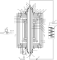
- FIG. 1 is a schematic diagram illustrating a structure of the apparatus according to some embodiments of the present disclosure
- FIG. 2 is a schematic cross-sectional view of section A-A of FIG. 1 according to some embodiments of the present disclosure.
- system means for distinguishing different components, elements, members, parts, or assemblies of different levels.
- unit means for distinguishing different components, elements, members, parts, or assemblies of different levels.
- the words may be replaced by other expressions.
- Flowcharts are used in the present disclosure to illustrate the operations performed by the system according to some embodiments of the present disclosure. It should be understood that the front or rear operations may not be necessarily performed exactly in order. On the contrary, each step may be performed in reverse or simultaneously. At the same time, other operations may also be added to the procedures, or a certain step or several steps may be removed from the procedures.
- FIG. 1 is a schematic diagram illustrating a structure of the apparatus according to some embodiments of the present disclosure.
- FIG. 2 is a schematic cross-sectional view of section A-A of FIG. 1 according to some embodiments of the present disclosure.
- the present disclosure provides an evaluation apparatus for seal integrity of a wellbore in a full life cycle.
- the apparatus may include an oil pipe temperature and pressure simulation assembly, an oil casing annular temperature and pressure simulation assembly, a formation confining pressure simulation assembly, a casing-cement sheath-formation combination preparation assembly, a blowby characteristic detection assembly, and a monitoring system 52 .
- the oil pipe temperature and pressure simulation assembly may be configured to realize an alternating simulation of an internal temperature, a pressure, a fluid phase change, a vibration, a bulge, deformation, and other states of the oil pipe during the oil and gas well production operation.
- the oil pipe temperature and pressure simulation assembly may include an oil pipe 1 , an oil pipe booster pump 42 , and a heating and cooling cycle apparatus 43 that are connected in sequence to form a loop.
- the oil pipe 1 may refer to a pipeline for conveying fuel oil.
- the diameter and arrangement of the oil pipe 1 may be determined in various ways, such as experiments, simulations, or the like.
- the oil pipe 1 may be provided with an oil pipe temperature and pressure sensor 46 .
- the oil pipe temperature and pressure sensor 46 may refer to a sensor apparatus for monitoring the temperature and pressure in the oil pipe 1 , which may be a sensor for integral measurement of temperature and pressure, or a separate temperature sensor and pressure sensor, which are not limited in the present disclosure.
- the oil pipe booster pump 42 may refer to an apparatus for pressurizing the oil pipe to ensure the oil pipe conveying capacity.
- the oil pipe booster pump 42 may be of various types, which may be an air-type booster pump, a gas-liquid type booster pump, a chlorine-type booster pump, or the like.
- the heating and cooling cycle apparatus 43 may refer to an apparatus that integrates heating and cooling, which may be configured to heat and cool the circulating fluid in the oil pipe 1 .
- the outflow port 36 of oil pipe 1 may be connected with the input end of an oil pipe booster pump 42 .
- An output end of the heating and cooling cycle apparatus 43 may be connected with an inflow port 35 of the oil pipe 1 , and the connected oil pipe may be provided with an oil pipe valve 56 that flows in a direction from the heating and cooling cycle apparatus 43 to the oil pipe 1 .
- the oil pipe valve 56 may refer to an apparatus that is configured to control the oil pipe 1 to communicate with the oil pipe booster pump 42 and the heating and cooling cycle apparatus 43 .
- the oil pipe 1 When the oil pipe valve 56 is in the open state, the oil pipe 1 may be communicated with the oil pipe booster pump 42 and the heating and cooling cycle apparatus 43 .
- the oil pipe booster pump 42 and the heating and cooling cycle apparatus 43 may respectively regulate the pressure and temperature in the oil pipe 1 .
- the oil pipe temperature and pressure simulation assembly may pressurize and depressurize the circulation system based on the oil pipe booster pump 42 and the oil pipe valve 56 , heat and cool the circulating fluid based on the heating and cooling cycle apparatus 43 , and real-time monitor and record the oil pipe temperature and pressure curve based on the oil pipe temperature and pressure sensor 46 and the monitoring system 52 .
- the oil pipe temperature and pressure simulation assembly may further simulate complex alternating load states such as temperature, pressure, fluid phase change, vibration, bulging, deformation, etc. in various production operation conditions of oil and gas wells, and test the critical blowby pressure of the casing-cement sheath-formation combination under the operation condition to evaluate the influence of oil pipe temperature and pressure fluctuations on the seal integrity of the combination during production operations.
- the circulation system may refer to a circuit composed of the oil pipe 1 , the oil pipe booster pump 42 , the heating and cooling cycle apparatus 43 , and oil pipe valve 56 .
- the monitoring system 52 please refer to the relevant description below.
- the oil casing annular temperature and pressure simulation assembly may be configured to realize an alternating simulation of an internal temperature, a pressure, a fluid phase change, a vibration, a bulge, deformation, and other states of the oil casing annular space during the oil and gas well production operation.
- the oil casing annular temperature and pressure simulation assembly may include a casing 2 and a booster pump 44 .
- the casing 2 may refer to a pipeline arranged on an outer layer of the oil pipe 1 and coaxial with the oil pipe 1 .
- the distance between the inner surface of the casing 2 and the outer surface of the oil pipe 1 may be determined based on various manners such as experiments and simulations.
- the booster pump 44 may be an apparatus for pressurizing the space formed between the inner surface of the casing 2 and the outer surface of the oil pipe 1 .
- the booster pump 44 may be of the same type as the oil pipe booster pump 42 , such as an air-pump booster pump, a gas-liquid booster pump, or the like.
- the casing 2 may be coaxial with the oil pipe 1 , and the oil casing annular space 37 may be formed between the inner surface of the casing 2 and the outer surface of the oil pipe 1 by sealing, the booster pump 44 may be communicated with the oil casing annular space 37 through an oil casing annular space pressure pipeline 51 , the oil casing annular space pressure pipeline 51 may be provided with an oil casing annular space valve 53 , and an oil casing annular space temperature and pressure sensor 47 may be arranged in the oil casing annular space 37 .
- the oil casing annular space 37 may refer to a sealed space formed between the inner surface of the casing 2 and the outer surface of the oil pipe 1 .
- the oil casing annular space pressure pipeline 51 may refer to the connection channel between the casing 2 and the booster pump 44 and the oil casing annular space valve 53 .
- the oil casing annular space valve 53 may be an apparatus that is configured to control the communication between the casing 2 and the booster pump 44 .
- the casing 2 When the oil casing annular space valve 53 is in an open state, the casing 2 may be communicated with the booster pump 44 , and the booster pump 44 may be configured to pressurize the casing 2 .
- the oil casing annular space temperature and pressure sensor 47 may refer to a sensor apparatus for monitoring the temperature and pressure in the oil casing annular space 37 .
- the oil casing annular space temperature and pressure sensor 47 may be a sensor for integral measure of temperature and pressure, or may be a separate temperature sensor and pressure sensor, which is not limited in the present disclosure.
- the oil casing annular temperature and pressure simulation assembly may simulate oil and gas wells to introduce gas-liquid fluid in the oil casing annular space 37 , use the oil casing annular space pressure pipeline 51 , the booster pump 44 , and the oil casing annular space valve 53 to pressurize and depressurize the oil casing annular space 37 , use the heating sleeve 38 to heat up and cool down the oil casing annular space 37 , and use the oil casing annular space temperature and pressure sensor 47 and the monitoring system 52 to monitor and record the temperature and pressure curve of the oil casing annular space 37 in real time.
- the oil casing annular temperature and pressure simulation assembly may further simulate complex alternating load states of the casing 2 and the casing annular space 37 such as temperature, pressure, fluid phase change, vibration, bulging, deformation, etc., caused by various production operation conditions of oil and gas wells and the correlation effect of various components of the wellbore, and test the critical blowby pressure of the casing-cement sheath-formation combination under the production operation condition to evaluate the influence of the fluctuations of operation conditions of the oil pipe 1 , the casing 2 , oil casing annular space 37 caused by the production operations on the seal integrity of the combination.
- the heating sleeve 38 please refer to the relevant descriptions below.
- the formation confining pressure simulation assembly may be configured to realize the alternating simulation of formation temperature, formation pressure around the wellbore, and non-uniform crustal stress near the wellbore.
- the formation confining pressure simulation assembly may include a high-pressure cylinder 18 , a heating sleeve 38 , a high-pressure cylinder plug 19 , and a formation confining pressure pipeline 45 .
- the high-pressure cylinder 18 may refer to a member that is coaxially arranged on the outer layer of the casing 2 and may be configured to withstand external pressure.
- the distance between the inner surface of the high-pressure cylinder 18 and the outer surface of the casing 2 may be determined based on experiments, simulations, or the like.
- the heating sleeve 38 may be a member for temperature regulation.
- the heating sleeve 38 may be arranged on the outer surface of a certain component to directly heat the component or heat the space formed based on the component.
- the heating sleeve 38 may be configured to heat the oil casing annular space 37 , etc.
- the high-pressure cylinder plug 19 may be a member for sealing the space between the inner surface of the high-pressure cylinder 18 and the outer surface of the sleeve 2 . More descriptions of the high-pressure cylinder plug 19 , reference may be found in the related descriptions below.
- the formation confining pressure pipeline 45 may refer to a connection channel of the high-pressure cylinder plug 19 , a booster pump 44 and a formation booster valve 55 .
- the formation booster valve 55 may be an apparatus for controlling the communication between the high-pressure cylinder plug 19 and the booster pump 44 .
- the high-pressure cylinder plug 19 may be communicated with the booster pump 44 .
- the booster pump 44 may be configured to pressurize the closed space formed between the inner surface of the high-pressure cylinder 18 and the outer surface of the casing 2 .
- the heating sleeve 38 may be sleeved on an outer surface of the high-pressure cylinder 18 , and the high-pressure cylinder 18 and the casing 2 may be coaxially arranged, and a closed space may be formed between an inner surface of the high-pressure cylinder 18 and an outer surface of the casing 2 through the high-pressure cylinder plug 19 , one end of the formation confining pressure pipeline 45 may be communicated with the closed space, and other end of the formation confining pressure pipeline 45 may be connected with the booster pump 44 , and the formation confining pressure pipeline 45 may be provided with a formation confining pressure valve 55 , and a formation temperature and pressure sensor 48 may be arranged in the closed space.
- the formation temperature and pressure sensor 48 may refer to a sensor apparatus for monitoring the temperature and pressure in the above-mentioned enclosed space. Like the above temperature and pressure sensor, the formation temperature and pressure sensor 48 may be a sensor with integral measure of temperature and pressure, or may be a separate temperature sensor and pressure sensor, which is not limited in the present disclosure.
- the formation confining pressure simulation assembly may add gas-liquid fluid to simulate the formation rock around the well, use the heating sleeve 38 to heat up and cool down the closed system, use the booster pump 44 , the formation confining pressure pipeline 45 , and the formation confining pressure valve 55 to pressurize and depressurize the closed system, and use the formation temperature and pressure sensor 48 and the monitoring system 52 to monitor and record the temperature and pressure curve of the closed system in real time.
- the formation confining pressure simulation assembly may further simulate the complex alternating load state of non-uniform crustal stress of the formation around the wellbore caused by various production operation conditions of oil and gas wells and the correlation effects of temperature, pressure and crustal stress around the wellbore, and test the critical blowby pressure of the casing-cement sheath formation combination under the production operation conditions to evaluate the influence of fluctuation of working conditions of pipe 1 , casing 2 , annular space and formation around the well caused by the production operations on the seal integrity of the combination.
- the closed system may refer to a system closed by components such as the high-pressure cylinder 18 and the high-pressure cylinder plug 19 .
- the casing-cement sheath-formation combination preparation assembly may be configured to prepare a casing-cement sheath-formation combination.
- the casing-cement sheath-formation combination preparation assembly may be disposed in the above-mentioned closed space, which may include a formation rock 4 , a sealing sleeve 5 , an upper core plug 6 , a lower core plug and a combination fastener.
- the formation rock 4 may refer to the formation rock that is arranged on the outer surface of the casing 2 and coaxial with the casing 2 in a closed space.
- the distance between the inner surface of the formation rock 4 and the outer surface of the casing 2 may be determined based on experiments, simulations, or the like.
- the sealing sleeve 5 may be a member for sealing the outer surface of the formation rock 4 .
- the sealing sleeve 5 may be a copper sleeve and may be made of red copper. It should be noted that, in addition to the red copper sleeve used as the sealing sleeve 5 in the embodiment, other materials that withstand pressure and seal the outer surface of the formation rock 4 may also be used as the sealing sleeve 5 , which is not limited in the present disclosure.
- the formation rock 4 may be a pore structure, and in the indoor evaluation apparatus, the size of the formation rock 4 may be limited, and when detecting the blowby pressure of the cement sheath, the pressure may spread from the formation rock 4 to the closed space, making the blowby pressure test inaccurate.
- the occurrence of this situation may be prevented by covering the outer surface of the formation rock 4 with the sealing sleeve 5 , so that the test result is closer to the result of the actual formation, and the accuracy of the evaluation result is improved.
- the upper core plug 6 and the lower core plug may be members for sealing the upper and lower end faces of the formation rock 4 , respectively.
- the upper core plug 6 may have the same structure as the lower core plug, and may be symmetrically arranged on both ends of the formation rock 4 .
- the combination fastener may be a member for fixing the whole formed by the cement sheath 3 , the formation rock 4 , the sealing sleeve 5 , the upper core plug 6 and the lower core plug on the casing 2 . More descriptions of the cement sheath 3 and the combination fastener, reference may be found in the related descriptions below.
- the above-mentioned whole is fixed by the combination fastener, which may effectively prevent the whole from sliding on the casing.
- the formation rock 4 and the casing 2 may be arranged coaxially, and a cement sheath space may be formed between an inner surface of the formation rock 4 and an outer surface of the casing 2 , a cement sheath 3 may be formed by injecting a cement slurry system into the cement sheath space for solidification, a bottom of the upper core plug 6 and a bottom of the lower core plug may be provided with pressure grooves 41 , and the pressure grooves 41 may be communicated with the cement sheath space, and the pressure groove 41 of the lower core plug may be connected with the booster pump 44 through a pressure detection inlet pipeline 39 , and the pressure detection inlet pipeline 39 may be provided with a channeling pressure sensor 49 and a channeling valve 54 in turn.
- the pressure groove 41 of the upper core plug 6 may be connected with a blowby pressure sensor 50 through a pressure detection outlet pipeline 40 .
- the pressure groove 41 may be a notch for pressurizing the cement sheath space.
- the pressure groove 41 of the lower core plug in order to prevent the cement slurry from clogging the pressure groove 41 of the lower core plug when the cement slurry system is poured, in the evaluation apparatus, is provided with an impermeable cloth or a filter screen, etc., through which gas can pass but the cement slurry cannot pass for clogging. More descriptions of the cement slurry system, reference may be found in the related descriptions below.
- the pressure detection inlet pipeline 39 may refer to a connection channel between the lower core plug and the channeling pressure sensor 49 , the channeling valve 54 and the booster pump.
- the channeling pressure sensor 49 may be a pressure sensor that is configured to channeling detection.
- the channeling valve 54 may be an apparatus for controlling the communication between the booster pump 44 and the channeling pressure sensor 49 and the lower core plug.
- the pressure detection outlet pipeline 40 may refer to a connection channel between the upper core plug 6 and the blowby pressure sensor 50 .
- the blowby pressure sensor 50 may be a pressure sensor that is configured to blowby monitoring.
- the pressure of the casing during the cementing operation may be simulated by applying pressure to the oil casing annular space 37
- the temperature of the formation during the cementing operation may be simulated by raising the temperature of the heating sleeve 38
- the formation confining pressure around the well may be simulated by applying pressure to the inside of the high-pressure cylinder 18
- the solidification process of cement slurry system may be completed under simulated cementing working conditions
- the canned cement slurry system solidifies to form a cement sheath 3 , which can finely simulate the wellbore cementing operation conditions and prepare a casing-cement sheath-formation combination.
- the cyclic alternating operation conditions of the oil pipe during the production operation may be simulated by applying alternating temperature and pressure to the oil pipe 1 through the fluid inlet 35 of the oil pipe 1
- the alternating operation conditions of the casing and the annular space during the production operation may be simulated by applying alternating temperature and pressure to the oil casing annular space 37 through the oil casing annular space pressure line 51 and the oil casing annular space valve 53
- the alternating temperatures of the oil pipe 1 , the casing 2 and the formation during the production operation may be simulated through the heating and cooling of the heating sleeve 38
- the alternating operation condition of the formation confining pressure around the well during the production operation may be simulated by applying the alternating temperature and pressure to the interior of the high-pressure cylinder 18 through the formation confining pressure pipeline 45 and the formation confining pressure valve 55
- the temperature and pressure alternating curve of the production operation conditions of the full life cycle may be recorded in real time
- the blowby characteristic detection assembly may be configured to realize real-time monitoring of the critical blowby pressure of the cement sheath.
- the critical blowby pressure of the cement sheath may refer to the minimum pressure that the casing-cement sheath-formation combination is subjected to when the blowby occurs.
- the blowby characteristic detection assembly may include, but is not limited to, a channeling pressure sensor 49 , a blowby pressure sensor 50 , or the like.
- the blowby characteristic detection assembly may pressurize and depressurize the blowby channel through the booster pump 44 and the channeling valve 54 , monitor and record the channeling pressure curve in real time through the channeling pressure sensor 49 and the monitoring system 52 , and monitor and record the blowby pressure curve in real time through the blowby pressure sensor 50 and the monitoring system 52 to test the critical blowby pressure of the casing-cement sheath-formation combination during the entire production operation to evaluate the seal integrity of the casing-cement sheath-formation assembly throughout the full life cycle.
- the monitoring system 52 may be configured to monitor the temperature and pressure conditions in each component, and record data curves.
- the monitoring system 52 may be a terminal device, for example, a desktop computer, a tablet computer, a notebook computer and other intelligent electronic device that may realize data processing and data communication.
- the monitoring system 52 may be connected with the oil pipe temperature and pressure sensor 46 , the oil casing annular space temperature and pressure sensor 47 , the formation temperature and pressure sensor 48 , the channeling pressure sensor 49 , and the blowby pressure sensor 50 , respectively.
- the monitoring system 52 may monitor and control experimental parameters such as temperature and pressure of each component in real time and accurately simulate operation conditions of oil and gas well cementing and various production operations to accurately and reliably measure the critical blowby pressure of the casing-cement sheath-formation combination under this working conditions.
- the casing 2 and the oil pipe 1 , the casing 2 and the high-pressure cylinder plug 19 , the high-pressure cylinder plug 19 and the high-pressure cylinder 18 , the upper core plug 6 and the casing 2 , and the lower core plug and the casing 2 may be all connected by flanges and bolts. Further, a sealing assembly may be provided between the components connected by the flange.
- the sealing assembly may refer to a member having sealing properties, such as a rubber sealing ring, or the like.
- the sealing assembly may include a casing flange sealing assembly 29 , a casing core plug sealing assembly 7 , a high-pressure cylinder plug core plug sealing assembly 26 , a high-pressure cylinder plug sealing assembly 20 , a high-pressure cylinder plug flange sealing assembly 23 , and other assembly. More descriptions of the above-mentioned sealing assembly, reference may be found in the related descriptions blow. It should be noted that, in addition to the rubber sealing ring, other materials or structures that may enhance the sealing performance may also be used as the sealing assembly, which is not limited in the present disclosure.
- the top of the casing 2 and the bottom of the casing 2 may be respectively connected with the upper and lower parts of the oil pipe 1 through a casing flange 30 and a casing flange bolt 31 .
- a casing flange sealing assembly 29 may be arranged between the casing flange 30 and the casing 2 .
- the top of the casing flange 30 may be further provided with a casing flange sealing flange 33 and a casing flange sealing flange bolt 34 .
- the casing flange 30 and the casing flange bolt 31 may be respectively the flange and the bolt that are configured to fix the connection between the casing 2 and the oil pipe 1 .
- the casing flange sealing assembly 29 may be a member for sealing the connection of the casing flange 30 and the casing 2 .
- the casing flange sealing flange 33 and the casing flange sealing flange bolt 34 may be flanges and bolts for sealing the casing flange 30 and the casing flange bolt 31 respectively.
- the upper core plug 6 and the lower core plug may be all connected with the casing 2 by the casing core plug sealing flange 16 and the casing core plug sealing flange bolt 17 , and a casing core plug sealing assembly 7 may be arranged between the casing core plug sealing flange 16 and the casing 2 .
- the casing core plug sealing flange 16 and the casing core plug sealing flange bolt 17 may be respectively the flange and the bolt that are configured to fix connection of the casing 2 with upper core plug 6 and lower core plug.
- the casing core plug sealing assembly 7 may be a member for sealing the connection between the casing core plug sealing flange 16 and the casing 2 .
- the high-pressure cylinder plug 19 may include an upper high-pressure cylinder plug and a lower high-pressure cylinder plug.
- the upper high-pressure cylinder plug and the upper core plug 6 , and the lower high-pressure cylinder plug and the lower core plug may be both connected with a high-pressure cylinder plug core plug sealing flange 27 and a high-pressure cylinder plug core plug sealing bolt 28 , and a high-pressure cylinder plug core plug sealing assembly 26 may be arranged between the high-pressure cylinder plug 19 and the core plug.
- the upper high-pressure cylinder plug and the lower high-pressure cylinder plug may refer to the high-pressure plugs that are respectively arranged on the upper and lower ends of the apparatus.
- the high-pressure cylinder plug core plug sealing flange 27 and the high-pressure cylinder plug core plug sealing bolt 28 may be respectively flanges and bolts used for fixing the connection between the high-pressure cylinder plug 19 and the core plug.
- the high-pressure cylinder plug core plug sealing assembly 26 may be a member for sealing the connection between the high-pressure cylinder plug 19 and the core plug.
- the high-pressure cylinder plug 19 and the high-pressure cylinder 18 may be connected by the high-pressure cylinder plug flange 21 and the high-pressure cylinder plug bolt 22 , and a high-pressure cylinder plug sealing assembly 20 may be arranged between the high-pressure cylinder plug 19 and the high-pressure cylinder 18 .
- the top of the high-pressure cylinder plug flange 21 may be provided with a high-pressure cylinder plug flange sealing flange 24 and a high-pressure cylinder plug flange sealing flange bolt 25 , and a high-pressure cylinder plug flange sealing assembly 23 may be also provided between the high-pressure cylinder plug flange sealing flange 24 and the high-pressure cylinder plug 19 .
- the high-pressure cylinder plug flange 21 and the high-pressure cylinder plug bolt 22 may be respectively flanges and bolts for the fixed connection of the high-pressure cylinder plug 19 and the high-pressure cylinder 18 .
- the high-pressure cylinder plug sealing assembly 20 may be a member configured to seal the connection between the high-pressure cylinder plug 19 and the high-pressure cylinder 18 .
- the high-pressure cylinder plug flange sealing flange 24 and the high-pressure cylinder plug flange sealing flange bolt 25 may be respectively flanges and bolts that are configured to further seal the high-pressure cylinder plug 19 and the high-pressure cylinder plug flange 21 .
- the high-pressure cylinder plug flange sealing assembly 23 may be a member configured to further seal the connection between the high-pressure cylinder plug flange sealing flange 24 and the high-pressure cylinder plug 19 .
- the combination fastener may include a sealing sleeve fixing flange 8 , a combination tensioning flange 9 , a tie rod 10 , a sealing sleeve core plug sealing assembly 11 , a tensioning flange core plug sealing assembly 12 , a tensioning flange sealing flange 13 , a tensioning flange sealing flange bolt 14 , and a combination tensioning flange bolt 15 .
- the sealing sleeve fixing flange 8 may be a flange for fixing the sealing sleeve 5 .
- the combination tensioning flange 9 may be a flange for tensioning and fixing the combination.
- the tie rod 10 may be a rod for tensioning the combination, one end of the tie rod 10 passes through the combination tensioning flange 9 at the top of the whole and is fastened by the combination tensioning flange bolt 15 , and the other end of the tie rod 10 passes through the combination tensioning flange 9 at the bottom of the whole and is fastened by the combination tensioning flange bolt 15 , and other end of the tie rod 10 passes through the combination tensioning flange 9 at bottom of the whole and is fastened by the combination tensioning flange bolt 15 .
- the combination tensioning flange bolt 15 may be a bolt for tensioning and fixing the combination.
- the sealing sleeve core plug sealing assembly 11 may be a sealing assembly for sealing the connection between the sealing sleeve 5 and the core plug.
- the tensioning flange core plug sealing assembly 12 may be a sealing assembly for sealing the connection between the combination tensioning flange 9 and the core plug.
- the tensioning flange sealing flange 13 and the tensioning flange sealing flange bolt 14 may be a respectively flange and a bolt that are configured to further seal the combination tensioning flange 9 .
- the tightness of the evaluation apparatus for seal integrity of the wellbore in the full life cycle may be effectively guaranteed, so as to ensure the accuracy of the test results of the simulation.
- the evaluation apparatus for seal integrity of the wellbore in the full life cycle may further include a heating apparatus (not shown in figure).
- the heating apparatus may be an oil pipe heater, etc., which is not limited in the present disclosure.
- the heating apparatus may be arranged in the oil pipe 1 to simulate that the oil pipe 1 , the casing 2 and the formation rock 4 are in an unsteady heat transfer state.
- the unsteady heat transfer state may refer to a heat conduction process in which the temperature of the object changes with time, such as the heating or cooling process of the oil pipe 1 , or the like.
- the present disclosure may provide an evaluation method for seal integrity of a wellbore in a full life cycle, the method may include the following operations.
- S1 designing an evaluation apparatus for seal integrity of a wellbore in a full life cycle with the size parameters of the oil pipe 1 , the casing 2 , and cement sheath 3 consistent with or similar to the target well section based on the wellbore parameters and working conditions of deep and ultra-deep wells, high-temperature and high-pressure wells, injection-production wells, and geothermal wells, analyzing the operation conditions experienced by the well in the full life cycle, selecting one or more operation conditions with high temperature and pressure and large alternating load, determining a temperature, a pressure and fluctuations of the temperature and pressure of the oil pipe 1 , an oil casing annular space 37 and a formation caused by each operation condition, determining a fluid composition, a gas-liquid multiphase flow state, and a transition condition of a critical state in the oil pipe 1 and the oil casing annular space 37 , and determining a formation pressure and fluctuation of the formation pressure under various operation conditions based on the oil and gas well production operation well history data.
- the target well section may refer to a well section that needs to be studied, such as a certain section of a deep well and an ultra-deep well.
- the wellbore parameters may refer to parameters related to the wellbore, such as the length, diameter, etc. of the wellbore.
- the working condition may refer to the environmental condition of the environment where the wellbore is located, such as ambient temperature and humidity.
- the oil and gas well production operation well history data may refer to a collection of data of the oil and gas well in the past production operation process.
- the operation condition may refer to an environmental condition of oil and gas wells during production operation, such as temperature, pressure, etc. during operation.
- S2 carrying out a pressure test on the evaluation apparatus to determine that the temperature resistance preformation, pressure bearing performance, and a sealing performance of the evaluation apparatus meet the experimental requirements of the target well section, determining a temperature and pressure alternating, a fluid phase transition and experiment of period parameter of each assembly of the evaluation apparatus.
- the pressure test may be performed on the oil pipe temperature and pressure simulation assembly, the casing annulus temperature and pressure simulation assembly, the formation confining pressure simulation assembly, and the blowby characteristic detection assembly to determine that the temperature resistance preformation, the pressure bearing performance, and the sealing performance of the evaluation apparatus meet the experimental requirements of the target well section, and the experimental condition parameters of each assembly such as temperature and pressure alternating, fluid phase transition and experimental period based on the wellbore cementing condition, operation condition, and the performance of the cement slurry system.
- the wellbore cementing condition may refer to an environmental condition when the wellbore is cemented.
- the performance of the cement slurry system may refer to the performance related to the cement slurry system, such as anti-leakage performance, anti-gas channeling performance, or the like.
- the cement slurry system may refer to the working fluid system used in cementing, such as low density and high strength system, polyvinyl alcohol system, etc.
- the actual cementing working condition may refer to the working condition in the actual cementing operation process.
- the wellbore working fluid may refer to a type of fluid used in oil and gas well drilling engineering.
- the steady-state heat transfer state may mean that the temperature of each point in the heat transfer system only varies with location, but not with time.
- the evaluation apparatus before using the wellbore cementing working conditions determined in the S2 to complete the solidification of the casing-cement sheath-formation combination, the evaluation apparatus needs to be assembled.
- the assembling process of the evaluation apparatus may include the following operations.
- S31 assembling the casing-cement sheath-formation combination preparation assembly.
- the casing 2 may be penetrated into the formation rock 4 , the lower core plug, the casing core plug sealing assembly 7 , the sealing sleeve core plug sealing assembly 11 may be installed, the cementing slurry system may be prepared, and the cementing slurry system may be gently poured into the annular space formed by the casing 2 and the formation rock 4 .
- the upper core plug 6 , the casing core plug sealing assembly 7 , the sealing sleeve core plug sealing assembly 11 may be installed, and the sealing sleeve 5 may be tightly wrapped in the outer layer of the formation rock 4 , and the axial direction of the sealing sleeve 5 may be tightened to avoid gap and deformation.
- the sealing sleeve fixing flange 8 , the combination tensioning flange 9 , the tie rod 10 , the tensioning flange core plug sealing assembly 12 , the tensioning flange sealing flange 13 , the tensioning flange sealing flange bolt 14 and a combination tensioning flange bolt 15 may be installed to complete the canning of the cement slurry system and the assembly of the casing cement sheath formation assembly preparation assembly.
- the high-pressure cylinder 18 may be sheathed outside the casing-cement sheath-formation combination preparation assembly. Then, a casing core plug sealing flange 16 , a casing core plug sealing flange bolt 17 , a high-pressure cylinder plug 19 , a high-pressure cylinder plug sealing assembly 20 , a high-pressure cylinder plug flange 21 , a high-pressure cylinder plug bolt 22 , a high-pressure cylinder plug flange sealing assembly 23 , a high-pressure cylinder plug flange sealing flange 24 , a high-pressure cylinder plug flange sealing flange bolt 25 , a high-pressure cylinder plug core plug sealing assembly 26 , a high-pressure cylinder plug core plug sealing flange 27 , a high-pressure cylinder plug core plug sealing bolt 28 , a heating sleeve 38 , a booster pump 44 , a formation confining pressure pipeline 45 ,
- S33 assembling the oil casing annular temperature and pressure simulation assembly.
- the oil pipe 1 may be inserted into the casing 2 .
- a casing sealing assembly 29 a casing flange 30 , a casing flange bolt 31 , a casing flange sealing assembly 32 , a casing flange sealing flange 33 , a casing flange sealing flange bolt 34 , an oil casing annular space temperature and pressure sensor 47 , an oil casing annular space pressure pipeline 51 , an oil casing annular space valve 53 may be installed in sequence to form a closed system of the oil casing annular space, that is, the assembly of the oil casing annular space temperature and pressure simulation assembly is completed.
- the oil pipe temperature and pressure sensor 46 may be installed inside the oil pipe 1 . Then, the fluid inlet 35 of the oil pipe 1 and the fluid outlet 36 of the oil pipe 1 may be connected with the oil pipe booster pump 42 , the heating and cooling cycle apparatus 43 , and the oil pipe valve 56 through an adapter to form a closed system of the oil pipe, that is, the assembly of the oil pipe temperature and pressure simulation assembly is completed.
- the booster pump 44 , the channeling pressure sensor 49 , and the channeling valve 54 may be connected with the pressure detection inlet line 39 .
- the blowby pressure sensor 50 may be connected with the pressure detection outlet pipeline 40
- the monitoring system 52 may be connected with the channeling pressure sensor 49 and the blowby pressure sensor 50 to form a circulation loop for monitoring the blowby pressure, that is, the assembly of the blowby characteristic detection assembly is completed.
- S36 connecting the monitoring system 52 .
- the oil pipe temperature and pressure sensor 46 , the oil casing annular space temperature and pressure sensor 47 , and the formation temperature and pressure sensor 48 may be further connected with the monitoring system 52 respectively to meet the requirements of cementing and production operation conditions for the function of real-time monitoring and data curve recording of the temperature and pressure conditions of each assembly, that is, the connection of the monitoring system 52 is completed.
- the gas-liquid phase medium may be a mixed medium of a two-phase of gas and liquid.
- the annular protective fluid may be a fluid filled between the oil pipe 1 and the casing 2 .
- a heating apparatus may be inserted in the oil pipe 1 to simulate the unsteady heat transfer state of the oil pipe 1 , the casing 2 and the formation rock 4 .
- S6 repeating the S3-S5 to obtain the blowby pressure curve of casing-cement sheath-formation combination of the target well under various production operation conditions.
- the cement slurry system In response to a determination that the cement slurry system meets the seal integrity and critical blowby pressure requirements, the cement slurry system, the cementing conditions, and the production operation conditions meeting the requirements of the seal integrity of the wellbore in the full life cycle.
- the design parameters of seal integrity of the wellbores may be optimized by any feasible scheme.
- the design parameters of seal integrity of the wellbore be optimized may include the following operations. Multiple sets of first candidate optimization parameter combinations may be generated. At least one set of second candidate optimization parameter combination may be determined based on the multiple sets of first candidate optimization parameter combinations. The design parameters of seal integrity of the wellbores may be optimized based on each set of the multiple sets of the second candidate optimization parameter combinations, and S1-S7 may be repeated until the critical blowby pressure of the cement sheath meets the requirements of the seal integrity of the wellbore in the full life cycle.
- multiple sets of first candidate optimization parameter combinations be generated, that is, an initial population be generated, the initial population is composed of several individuals, and each individual may refer to a first candidate optimization parameter combination.
- the first candidate optimization parameter combination may refer to a candidate parameter combination related to the requirements of the seal integrity of the wellbore.
- Parameters combinations related to requirements of the seal integrity of the wellbore may be coded in various ways to obtain individual code.
- the individual code may include one or more combinations of slurry system parameters, cementing parameters, production characteristics, or the like.
- the cement slurry system parameter may include a selection of the system (e.g., polyvinyl alcohol system, latex system, etc.), a selection of constituent materials (e.g., reinforcing agent, fluid loss agent, etc.), and a proportion of each material, etc.
- the cementing parameter may include a selection of cementing process (e.g., liner cementing, inner pipe cementing, conventional cementing, etc.), a casing parameter (e.g., casing material, a pore diameter, and wall thickness, etc.), a selection of the drilling fluid, etc.
- the production characteristics may include a type of production operation conditions (e.g., production operations such as oil recovery or water injection after cementing is completed), a production operation parameter, etc.
- the individual code may also include other related features, which are not limited here.
- multiple sets of the first candidate optimization parameter combinations may be iteratively updated, and at least one second candidate optimization parameter combination may be determined from the iteratively updated first candidate optimization parameter combinations, which may include performing multiple rounds of iterative update on the first candidate optimization parameter combination until the preset condition is satisfied, and determining the second candidate optimization parameter combination.
- At least one round of the multiple rounds of iterative update may include performing a transformation on the selected first candidate optimization parameter combination to generate a new first candidate optimization parameter combination, and adding the new first candidate optimization parameter combination to the population of the current round of iterative update.
- the transformation may include crossover, mutation, duplication, etc.
- the first candidate optimization parameter combination may be selected based on the evaluation value of the first candidate optimization parameter combination in the initial population.
- the selected first candidate optimization parameter combination may be transformed. For example, a crossover operation may be performed on any two selected first candidate optimization parameter combinations to obtain two sets of new first candidate optimization parameter combinations.
- the values of parameters of the same type (e.g., cementing parameters) in two first candidate optimization parameter combinations may be exchanged.
- a mutation operation may be performed on the selected first candidate optimization parameter to obtain the new first candidate optimization parameter. For example, a certain parameter (e.g., cementing parameter) in a certain combination may be increased or decreased.
- the first candidate optimization parameter combination that meets the preset condition may be used as the second candidate optimization parameter combination.
- the preset condition may include that the evaluation value is greater than a threshold value or a maximum value, or the like.
- the second candidate optimization parameter combination may include one or more optimization parameter combinations.
- the preset times of iterations may be 100-1000, and under the condition that sufficient iterative calculation is ensured, better optimization results may be obtained quickly, and the calculation process may be accelerated.
- the evaluation value may be determined by a model.
- the individual code of the first candidate optimization parameter combination may be directly input into the evaluation value determination model, and the corresponding evaluation value may be output. More descriptions of the evaluation value determination model, reference may be found in the related descriptions below, which may not be repeated here.
- a preset number of first candidate optimization parameter combinations may be eliminated based on the evaluation value. For example, the evaluation values of the multiple first candidate optimization parameter combinations may be sorted in descending order, and then the first candidate optimization parameter combinations whose evaluation value ranks are lower than the preset rank threshold may be eliminated, and the remaining top N first candidate optimization parameter combinations remain in the population for the next round of iterative update. After multiple rounds of iterations until the first candidate optimization parameter combination that meets the preset condition is obtained, the second candidate optimization parameter combination is obtained.
- the evaluation value may indicate a feasibility of evaluating the optimization parameters.
- An evaluation value may be positively correlated with the feasibility of the optimization parameters. That is, the higher the feasibility of the optimization parameter is, the larger the evaluation value of optimization parameter is.
- the evaluation value determination model may be a machine learning model.
- the evaluation value determination model may include a pressure determination layer and an evaluation value determination layer, and the pressure determination layer and the evaluation value determination layer may be a model obtained by a convolutional neural network or a deep neural network or a combination thereof.
- an input of the pressure determination layer may include the individual code and geological (environmental) parameters (including, but not limited to, a density, a porosity, a permeability coefficient, a hydraulic conductivity, a pressure conduction coefficient, etc.) of the first candidate optimization parameter combination
- the output of the pressure determination layer may include the blowby pressure curve of the formation combination casing-cement sheath-formation combination, the channeling pressure of the lower part of the casing-cement sheath-formation combination, and the pressure of blowby to the upper part of the casing-cement sheath-formation combination.
- the output of the evaluation value determination layer may include the evaluation value.
- the evaluation value determination model may be obtained through separate training or joint training.
- the pressure determination layer and the evaluation value determination layer may be obtained through joint training, and then the evaluation value determination model may be obtained.
- the output of the pressure determination layer may be used as the input of the evaluation value determination layer.
- sample data may be input to an initial pressure determination layer
- the sample data may include multi-history data and/or simulation software simulation data
- the blowby pressure curve of the casing-cement sheath-formation combination the channeling pressure of the lower part of the casing-cement sheath-formation combination, and the pressure of blowby to the upper part of the casing-cement sheath-formation combination output by the initial pressure determination layer
- the evaluation value output by the initial evaluation value determination layer may be obtained.
- the manually labeled evaluation values based on monitored and/or simulated pressure values corresponding to each set of sample data may be used to verify the output results of the initial evaluation value determination layer to obtain verification data of the output result of the initial evaluation value determination layer using the back-propagation characteristics of the neural network model, and the verification data may be used to continue the training until the trained pressure determination layer and evaluation value determination layer are obtained.
- the sample data may also be input into the initial pressure determination layer, and the output result of the initial pressure determination layer may be input into the initial evaluation value determination layer, and the loss function may be constructed based on labels (manually labeled evaluation values based on the monitored and/or simulated pressure value corresponding to each set of sample data) and the output result of the initial evaluation value determination layer.
- the parameters of the initial pressure determination layer and the initial evaluation value determination layer may be updated until the initial pressure determination layer and the initial evaluation value determination layer meet the preset conditions, and the trained pressure determination layer and the trained evaluation value determination layer are obtained.
- the preset condition may be that the loss function is less than the threshold, converges, or the training period reaches the threshold.
- the method of iteratively updating model parameters may include conventional model training methods such as stochastic gradient descent.
- the output of the evaluation value determination model may also include the corresponding confidence levels of the blowby pressure curve of the casing-cement sheath-formation combination, the channeling pressure of the lower part of the casing-cement sheath-formation combination, and the blowby pressure of blowby to the upper part of the casing-cement sheath-formation combination.
- the confidence level may indicate the credibility of the output results.
- a corresponding confidence level threshold may be set for each output result, and when the corresponding confidence level of each output result is greater than the corresponding confidence level threshold, it means that the output result is highly reliable.
- the confidence level thresholds corresponding to each output result may be the same or different.
- the label of confidence level of the sample data corresponding to the historical data is the first preset value (e.g., 1)
- the label of confidence level of the sample data corresponding to the simulation software simulation data is the second preset value (e.g., 0.5).
- the determination of the second candidate optimization parameter combination may be related to a confidence level.
- the confidence level may play a role in increasing the selection range to a certain extent. For example, based on the original requirements, if one or more of the blowby pressure curve of the casing-cement sheath-formation combination, the channeling pressure of the lower part of the casing-cement sheath-formation combination, and the pressure of blowby to the upper part of the casing-cement sheath-formation combination output by the evaluation value determination model are not good enough, and the corresponding first candidate optimization parameter combination (individual) may be eliminated. However, if the corresponding confidence level of the output of the evaluation value determination model is low, it may be considered that the first candidate optimization parameter combination may not be eliminated temporarily.
- the first candidate optimization parameter combination may be temporarily remained in the population to continue to observe, and individuals with low confidence level in subsequent iterations may have a higher probability to transform.
- optimizing the design parameters of seal integrity of the wellbore may be accomplished in various ways. In some embodiments, optimizing the design parameters of seal integrity of the wellbore may be achieved based on any one or more of optimizing the cement slurry system, optimizing the design cementing conditions, and optimizing the adjustment of production operating parameters.
- the manner of determining the optimizing the design parameters of seal integrity of the wellbore may include the following operations.
- the estimated optimization effectiveness of optimizing the cement slurry system, optimizing the design of cementing conditions, and optimizing the adjustment of production operating parameters may be evaluated.
- the way of optimizing the design parameters of seal integrity of the wellbore may be determined based on the optimization effectiveness.
- selecting the optimizable parameters of one of the optimization directions to be optimized as the optimization scheme or selecting the optimizable parameters of various optimization directions to be optimized as the optimization scheme may be determined by the optimization effectiveness.
- the optimization effectiveness may refer to the parameters related to the selection of the optimization direction. The greater the optimization effectiveness of a certain optimization direction is, the greater the practicability and effectiveness of the optimization scheme obtained by the optimization based on the optimization direction is.
- one or more optimization directions whose optimization effectiveness is greater than a preset threshold may be selected, and an optimization scheme may be determined based on the selected optimization directions.
- the optimization effectiveness may be determined in a variety of feasible ways. For example, it may be determined using the selection rate, which may be determined based on the dimension scale of the optimization direction.
- the dimension scale may be used to describe the scale of the combination of optimizable parameters contained in the optimization direction.
- the dimension scale may be determined based on the number of optimizable parameters in the optimization direction, and the number of optional values for each optimizable parameter (e.g., multiplying).
- the selection rate of the optimization direction may be calculated based on the historical data, the historical simulation data, etc.
- the selection rate of the optimization direction is equal to the number of parameter combinations selected in the optimization direction/dimension scale.
- the selected parameter combination may be the one used in historical data with better effect and/or the one selected in historical simulation data with better effect.
- the calculated selection rate may be used as the optimization effectiveness of this dimension.
- a certain optimization direction includes an optimizable parameter A and an optimizable parameter B
- the optimizable parameter A may include optional values a1, a2 and a3
- the optimizable parameter B may include optional values b1, b2 and b3
- each candidate optimization parameter in each group of candidate optimization parameter combinations may belong to an optimization direction
- the first candidate optimization parameter combination may include optimizable parameters in three optimization directions, i.e., the optimizable parameters of optimizing the optimization direction of the parameters of the cement slurry system, the optimizable parameters of optimizing the optimization direction of optimizing the design of the cementing conditions, and the optimizable parameters of optimizing the optimization direction of optimizing the adjustment of the production operation parameters.
- the optimization effectiveness of each optimization direction may be obtained.
- the optimization direction with a low optimization effectiveness because its optimization effectiveness is low, the optimization of the parameters belonging to the optimization direction in the candidate optimization parameter combination is of little significance, and such parameters may not be transformed (e.g., using originally generated values) as much as possible.
- the parameters belonging to the optimization direction in the candidate optimization parameter combination may be transformed (e.g., by crossover, mutation, etc.) with a higher probability, so that it is convenient to quickly find a better solution. More descriptions of the obtaining method of the optimization effectiveness, reference may be found in the related descriptions of the aforementioned selection of optimization scheme, which may not be repeated here.
- the evaluation apparatus for seal integrity of the wellbore in the full life cycle may finely simulate the systemic effects of the wellbore barrier correlation such as extremely harsh wellbore oil pipe, casing, annular space and formation temperature and pressure cyclic alternating, oil casing bulging effect, vibration effect, fluid phase change, and cyclic alternating load on its seal integrity.
- the experimental parameters may be adjusted based on the load of the casing-cement sheath-formation combination and the effect of cyclic alternating temperature and pressure under the actual wellbore operation conditions, which is more suitable for simulating extremely severe wellbore operation conditions.
- numbers that describe the number of components and attributes are used. It should be understood that such numbers used to describe the embodiments are modified by the modifiers “approximately”, “approximately” or “generally” in some examples. For example, “about,” “approximate,” or “substantially” may indicate ⁇ 20% variation of the value it describes, unless otherwise stated. Accordingly, in some embodiments, the numerical parameters set forth in the description and attached claims are approximations that may vary depending upon the desired properties sought to be obtained by a particular embodiment. In some embodiments, the numerical parameters should be construed in light of the count of reported significant digits and by applying ordinary rounding techniques.
Landscapes
- Physics & Mathematics (AREA)
- Life Sciences & Earth Sciences (AREA)
- Engineering & Computer Science (AREA)
- Mining & Mineral Resources (AREA)
- Geology (AREA)
- General Physics & Mathematics (AREA)
- Biochemistry (AREA)
- Fluid Mechanics (AREA)
- Immunology (AREA)
- Pathology (AREA)
- Geophysics (AREA)
- Analytical Chemistry (AREA)
- Environmental & Geological Engineering (AREA)
- General Health & Medical Sciences (AREA)
- Chemical & Material Sciences (AREA)
- Health & Medical Sciences (AREA)
- General Life Sciences & Earth Sciences (AREA)
- Geochemistry & Mineralogy (AREA)
- Quality & Reliability (AREA)
- Testing Of Devices, Machine Parts, Or Other Structures Thereof (AREA)
- Testing Resistance To Weather, Investigating Materials By Mechanical Methods (AREA)
Abstract
Description
Claims (10)
Applications Claiming Priority (2)
| Application Number | Priority Date | Filing Date | Title |
|---|---|---|---|
| CN202111348685.5 | 2021-11-15 | ||
| CN202111348685.5A CN114033360B (en) | 2021-11-15 | 2021-11-15 | Full life cycle shaft seal integrity evaluation device and method |
Publications (2)
| Publication Number | Publication Date |
|---|---|
| US20230152196A1 US20230152196A1 (en) | 2023-05-18 |
| US12196725B2 true US12196725B2 (en) | 2025-01-14 |
Family
ID=80144398
Family Applications (1)
| Application Number | Title | Priority Date | Filing Date |
|---|---|---|---|
| US18/055,819 Active 2043-05-06 US12196725B2 (en) | 2021-11-15 | 2022-11-15 | Evaluation apparatus for seal integrity of wellbores in full life cycle and evaluation methods thereof |
Country Status (2)
| Country | Link |
|---|---|
| US (1) | US12196725B2 (en) |
| CN (1) | CN114033360B (en) |
Families Citing this family (17)
| Publication number | Priority date | Publication date | Assignee | Title |
|---|---|---|---|---|
| CN114658411B (en) * | 2022-03-17 | 2023-04-11 | 中国石油大学(华东) | Device and method for evaluating integrity of shaft after high-pressure oil and gas well pipe column is blocked |
| CN115012909B (en) * | 2022-06-09 | 2025-07-22 | 中煤科工集团沈阳研究院有限公司 | Gas extraction drilling hole sealing quality detection device and hole sealing quality evaluation method |
| CN115263278A (en) * | 2022-08-02 | 2022-11-01 | 西南石油大学 | A device and method for evaluating the integrity of a full-scale cement sheath under downhole conditions |
| CN117662117A (en) * | 2022-09-01 | 2024-03-08 | 中国石油天然气集团有限公司 | Testing system and method for radial stress changes in cement sheath caused by temperature difference effect |
| CN116296900B (en) * | 2023-05-25 | 2023-07-25 | 四川职业技术学院 | A control system and method for measuring shear stress change of river bottom gas pipeline |
| CN119434955A (en) * | 2023-08-03 | 2025-02-14 | 中国石油天然气股份有限公司 | A cementing interface peeling visualization test device and method |
| WO2025034128A1 (en) * | 2023-08-04 | 2025-02-13 | Роман Николаевич РЯЗАНОВ | Test stand for testing a remedial sealing composition |
| CN119531840A (en) * | 2023-08-31 | 2025-02-28 | 中国石油天然气股份有限公司 | Method, device, equipment and medium for evaluating cementing quality by multi-stage fracturing |
| CN119664318B (en) * | 2023-09-19 | 2026-01-23 | 中国石油天然气集团有限公司 | Method and device for determining dynamic pressure of shaft, electronic equipment and medium |
| CN117388440B (en) * | 2023-10-23 | 2024-07-12 | 中国矿业大学 | Device and method for grouting process test and effect detection between double-layer well walls |
| CN117468877B (en) * | 2023-12-26 | 2024-03-01 | 深蓝(天津)智能制造有限责任公司 | An automatic induction control method and device for electronically controlled packers based on neural network |
| CN120929894A (en) * | 2024-05-08 | 2025-11-11 | 中国石油天然气股份有限公司 | Oil pipe buckling quality evaluation model construction and evaluation method and intelligent buckling torque meter |
| EP4671492A1 (en) * | 2024-06-25 | 2025-12-31 | TotalEnergies OneTech | Replication device for replicating the behavior of oil and gas boreholes |
| CN120230621B (en) * | 2025-03-13 | 2025-11-25 | 中盐盐穴综合利用股份有限公司 | Reaction device for simulating hydrogen consumption of microorganisms in salt caverns and application method of reaction device |
| CN120946308A (en) * | 2025-08-01 | 2025-11-14 | 中国石油大学(北京) | Device and method for evaluating wellbore sealing performance under in-situ conditions of carbon dioxide geological storage |
| CN121253792B (en) * | 2025-12-05 | 2026-02-27 | 中国石油大学(北京)克拉玛依校区 | Device and method for evaluating the sealing of low-melting-point alloy wellbore plugging materials |
| CN121595243B (en) * | 2026-01-30 | 2026-04-24 | 中国石油大学(华东) | Ultra-deep gas well production string multi-mode leakage simulation experiment device and method |
Citations (11)
| Publication number | Priority date | Publication date | Assignee | Title |
|---|---|---|---|---|
| US20110094295A1 (en) * | 2009-10-28 | 2011-04-28 | Halliburton Energy Services, Inc. | Cement testing |
| CN104406910A (en) * | 2014-10-27 | 2015-03-11 | 西南石油大学 | Apparatus and method for testing cementation capability of well cementation first and second interfaces under high-temperature high-pressure conditions |
| US20170205388A1 (en) * | 2014-04-04 | 2017-07-20 | Schlumberger Technology Corporation | Wellbore cement simulator |
| US20180010438A1 (en) | 2015-03-20 | 2018-01-11 | Halliburton Energy Services Inc. | Dynamic sensing of the top of cement (toc) during cementing of a well casing in a well bore |
| US20180209928A1 (en) | 2015-09-25 | 2018-07-26 | Petrochina Company Limited | Method and device for detecting damage rate of an inner coating of a downhole oil casing |
| CN108361024A (en) | 2018-02-06 | 2018-08-03 | 西南石油大学 | The experimental provision and method that evaluation oil pipe shock loading influences cement sheath integrality |
| CN109681190A (en) * | 2019-03-07 | 2019-04-26 | 中国海洋石油集团有限公司 | Gas well at HTHP cement sheath sealing integrity evaluation system |
| CN109931048A (en) | 2019-03-27 | 2019-06-25 | 南智(重庆)能源技术有限公司 | Oil/gas well tubing and casing integrality detection method and evaluation system |
| CN210087307U (en) | 2019-05-27 | 2020-02-18 | 青岛理工大学 | High temperature and high pressure environment wellbore casing-cement ring cementation surface test device in hot dry rock formation |
| CN111927435A (en) | 2020-08-26 | 2020-11-13 | 西南石油大学 | High-temperature high-pressure casing cement sheath stratum seal integrity evaluation device and method |
| US20210246777A1 (en) | 2018-06-18 | 2021-08-12 | Gowell International, Llc | Apparatus and method for downhole light weight cement bond evaluation in wellbore |
-
2021
- 2021-11-15 CN CN202111348685.5A patent/CN114033360B/en active Active
-
2022
- 2022-11-15 US US18/055,819 patent/US12196725B2/en active Active
Patent Citations (12)
| Publication number | Priority date | Publication date | Assignee | Title |
|---|---|---|---|---|
| US20110094295A1 (en) * | 2009-10-28 | 2011-04-28 | Halliburton Energy Services, Inc. | Cement testing |
| US20170205388A1 (en) * | 2014-04-04 | 2017-07-20 | Schlumberger Technology Corporation | Wellbore cement simulator |
| CN104406910A (en) * | 2014-10-27 | 2015-03-11 | 西南石油大学 | Apparatus and method for testing cementation capability of well cementation first and second interfaces under high-temperature high-pressure conditions |
| US20180010438A1 (en) | 2015-03-20 | 2018-01-11 | Halliburton Energy Services Inc. | Dynamic sensing of the top of cement (toc) during cementing of a well casing in a well bore |
| US20180209928A1 (en) | 2015-09-25 | 2018-07-26 | Petrochina Company Limited | Method and device for detecting damage rate of an inner coating of a downhole oil casing |
| CN108361024A (en) | 2018-02-06 | 2018-08-03 | 西南石油大学 | The experimental provision and method that evaluation oil pipe shock loading influences cement sheath integrality |
| CN108361024B (en) * | 2018-02-06 | 2021-03-30 | 西南石油大学 | Experimental device and method for evaluating influence of oil pipe impact load on integrity of cement sheath |
| US20210246777A1 (en) | 2018-06-18 | 2021-08-12 | Gowell International, Llc | Apparatus and method for downhole light weight cement bond evaluation in wellbore |
| CN109681190A (en) * | 2019-03-07 | 2019-04-26 | 中国海洋石油集团有限公司 | Gas well at HTHP cement sheath sealing integrity evaluation system |
| CN109931048A (en) | 2019-03-27 | 2019-06-25 | 南智(重庆)能源技术有限公司 | Oil/gas well tubing and casing integrality detection method and evaluation system |
| CN210087307U (en) | 2019-05-27 | 2020-02-18 | 青岛理工大学 | High temperature and high pressure environment wellbore casing-cement ring cementation surface test device in hot dry rock formation |
| CN111927435A (en) | 2020-08-26 | 2020-11-13 | 西南石油大学 | High-temperature high-pressure casing cement sheath stratum seal integrity evaluation device and method |
Non-Patent Citations (7)
| Title |
|---|
| Ali Taghipour et al., Novel laboratory setup for realistic wellbore cement and formation integrity studies, Journal of Petroleum Science and Engineering, 1-7, 2021. |
| Guo, Yabin et al., Cementing Practices to Solve Well Integrity Challenges of Ultra Deep High Temperature Wells in Western China, Society of Petroleum Engineers, 1-19, 2016. |
| Notification to Grant Patent Right for Invention in Chinese Application No. 202111348685.5 mailed on Apr. 28, 2023, 6 pages. |
| Song, Dejun, Wellbore Integrity Evaluation Methodfor Complex Oil and Gas Wells in Tahe Oilfield, China Master's Theses Full-text Database( Engineering Science and Technology I Series): 1-72, 2021. |
| Xu, Honglin et al., Influence of the WHCP on cement sheath stress and integrity in HTHP gas well, Journal of Petroleum Science and Engineering, 174-180, 2014. |
| Zhang, Zhi et al., Research on risk evaluation of well integrity for sour gas wells, Journal of Safety Science and Technology, 13(4): 101-107, 2017. |
| Zhou, Shiming et al., Study on Failure Mechanism of Cement Sheath Sealing of Shale Gas Well Under Alternating Loading and the Controlling Method, International Petroleum Technology Conference, 1-9, 2019. |
Also Published As
| Publication number | Publication date |
|---|---|
| US20230152196A1 (en) | 2023-05-18 |
| CN114033360B (en) | 2023-05-26 |
| CN114033360A (en) | 2022-02-11 |
Similar Documents
| Publication | Publication Date | Title |
|---|---|---|
| US12196725B2 (en) | Evaluation apparatus for seal integrity of wellbores in full life cycle and evaluation methods thereof | |
| Therond et al. | Large scale testing & modelling for cement zonal isolation of water injection wells | |
| Zhou et al. | Nodal analysis for unconventional reservoirs—principles and application | |
| Prakasa et al. | Novel application of capacitance-resistance model for reservoir characterisation and zonal, intelligent well control | |
| Fleckenstein et al. | Development of multi-stage fracturing system and wellbore tractor to enable zonal isolation during stimulation and EGS operations in horizontal wellbores | |
| Wang et al. | Application of fuzzy analytic hierarchy process in sandstone aquifer water yield property evaluation | |
| CN107956430B (en) | Intelligent well completion pipe string suitable for land test well and well logging test method thereof | |
| Milad et al. | Modeling and simulation of production from commingled shale gas reservoirs | |
| Vlasov et al. | Experience of thermo-hydrodynamic studies of wells in combination with noise logging and quantitative interpretation of data based on the simulator | |
| Wooley et al. | Cementing temperatures for deep-well production liners | |
| Wu et al. | Research on rapid identification and evaluation technology for gas formation during underbalanced drilling | |
| Zhou et al. | Nodal Analysis for a Transient Production System—Principles and Application | |
| Zhu et al. | Analysis of borehole stability in gas drilling using a thermal elastoplastic coupling model | |
| Ding et al. | Modeling and prediction of sustained casing pressure of high-pressure and high-temperature gas wells during production operations | |
| Pu et al. | Prediction of the Control Effect of Fractured Leakage in Unconventional Reservoirs Using Machine Learning Method | |
| Ma et al. | Multi-Stage Fracturing Seepage Model and Productivity Prediction Method for Horizontal Wells in Shale Oil Reservoir-Use Horizontal Wells in Qingcheng Oil Field, China, as an Example | |
| Feng et al. | A prediction model for sustained casing pressure under the effect of gas migration variety | |
| Wang et al. | Sustained Casing Pressure: One of the Most Important Factors Determining the Integrity of Deepwater Wells | |
| Mesdour et al. | Comparison of Analytical Model Versus Numerical Model in Estimating EUR of Well Drilled and Completed in Unconventional Source Rock | |
| Rocha-Valadez et al. | Assessing Integrity of Gas-Lift Valves by Analyzing Annular Pressure-Transient Response | |
| CN120745265B (en) | Method for predicting the service life cycle of inclined cementing casing in super wells | |
| Villanueva-Triana et al. | Rigorous simulation of production from commingled multilayer reservoirs under various crossflow and boundary conditions | |
| Xiang et al. | Study on Breathing Effect Under the Coupled Flow Between Formation and Wellbore During Deepwater Drilling | |
| Cao et al. | A comprehensive model integrating the stress sensitivity for pressure transient behavior study on the two-zone system for offshore loose sandstone reservoirs | |
| Islam et al. | Influence of Large Drawdowns in Oil Reservoirs on Fluid Temperature and Fluid Properties |
Legal Events
| Date | Code | Title | Description |
|---|---|---|---|
| FEPP | Fee payment procedure |
Free format text: ENTITY STATUS SET TO UNDISCOUNTED (ORIGINAL EVENT CODE: BIG.); ENTITY STATUS OF PATENT OWNER: SMALL ENTITY |
|
| FEPP | Fee payment procedure |
Free format text: ENTITY STATUS SET TO SMALL (ORIGINAL EVENT CODE: SMAL); ENTITY STATUS OF PATENT OWNER: SMALL ENTITY |
|
| AS | Assignment |
Owner name: SOUTHWEST PETROLEUM UNIVERSITY, CHINA Free format text: ASSIGNMENT OF ASSIGNORS INTEREST;ASSIGNORS:HOU, DUO;ZHANG, ZHI;XIAO, ZHONGLING;AND OTHERS;REEL/FRAME:062047/0651 Effective date: 20221114 |
|
| STPP | Information on status: patent application and granting procedure in general |
Free format text: DOCKETED NEW CASE - READY FOR EXAMINATION |
|
| STPP | Information on status: patent application and granting procedure in general |
Free format text: NON FINAL ACTION MAILED |
|
| STPP | Information on status: patent application and granting procedure in general |
Free format text: RESPONSE TO NON-FINAL OFFICE ACTION ENTERED AND FORWARDED TO EXAMINER |
|
| STPP | Information on status: patent application and granting procedure in general |
Free format text: NOTICE OF ALLOWANCE MAILED -- APPLICATION RECEIVED IN OFFICE OF PUBLICATIONS |
|
| STPP | Information on status: patent application and granting procedure in general |
Free format text: PUBLICATIONS -- ISSUE FEE PAYMENT VERIFIED |
|
| STCF | Information on status: patent grant |
Free format text: PATENTED CASE |