US12193129B2 - Light emitting element driving device - Google Patents
Light emitting element driving device Download PDFInfo
- Publication number
- US12193129B2 US12193129B2 US17/781,836 US202017781836A US12193129B2 US 12193129 B2 US12193129 B2 US 12193129B2 US 202017781836 A US202017781836 A US 202017781836A US 12193129 B2 US12193129 B2 US 12193129B2
- Authority
- US
- United States
- Prior art keywords
- light emitting
- emitting element
- signal
- predetermined
- time point
- Prior art date
- Legal status (The legal status is an assumption and is not a legal conclusion. Google has not performed a legal analysis and makes no representation as to the accuracy of the status listed.)
- Active, expires
Links
Images


Classifications
-
- H—ELECTRICITY
- H05—ELECTRIC TECHNIQUES NOT OTHERWISE PROVIDED FOR
- H05B—ELECTRIC HEATING; ELECTRIC LIGHT SOURCES NOT OTHERWISE PROVIDED FOR; CIRCUIT ARRANGEMENTS FOR ELECTRIC LIGHT SOURCES, IN GENERAL
- H05B47/00—Circuit arrangements for operating light sources in general, i.e. where the type of light source is not relevant
- H05B47/10—Controlling the light source
- H05B47/175—Controlling the light source by remote control
- H05B47/19—Controlling the light source by remote control via wireless transmission
-
- H—ELECTRICITY
- H05—ELECTRIC TECHNIQUES NOT OTHERWISE PROVIDED FOR
- H05B—ELECTRIC HEATING; ELECTRIC LIGHT SOURCES NOT OTHERWISE PROVIDED FOR; CIRCUIT ARRANGEMENTS FOR ELECTRIC LIGHT SOURCES, IN GENERAL
- H05B45/00—Circuit arrangements for operating light-emitting diodes [LED]
- H05B45/50—Circuit arrangements for operating light-emitting diodes [LED] responsive to malfunctions or undesirable behaviour of LEDs; responsive to LED life; Protective circuits
- H05B45/58—Circuit arrangements for operating light-emitting diodes [LED] responsive to malfunctions or undesirable behaviour of LEDs; responsive to LED life; Protective circuits involving end of life detection of LEDs
-
- H—ELECTRICITY
- H05—ELECTRIC TECHNIQUES NOT OTHERWISE PROVIDED FOR
- H05B—ELECTRIC HEATING; ELECTRIC LIGHT SOURCES NOT OTHERWISE PROVIDED FOR; CIRCUIT ARRANGEMENTS FOR ELECTRIC LIGHT SOURCES, IN GENERAL
- H05B45/00—Circuit arrangements for operating light-emitting diodes [LED]
- H05B45/10—Controlling the intensity of the light
-
- H—ELECTRICITY
- H05—ELECTRIC TECHNIQUES NOT OTHERWISE PROVIDED FOR
- H05B—ELECTRIC HEATING; ELECTRIC LIGHT SOURCES NOT OTHERWISE PROVIDED FOR; CIRCUIT ARRANGEMENTS FOR ELECTRIC LIGHT SOURCES, IN GENERAL
- H05B47/00—Circuit arrangements for operating light sources in general, i.e. where the type of light source is not relevant
- H05B47/10—Controlling the light source
- H05B47/175—Controlling the light source by remote control
- H05B47/18—Controlling the light source by remote control via data-bus transmission
-
- B—PERFORMING OPERATIONS; TRANSPORTING
- B60—VEHICLES IN GENERAL
- B60Q—ARRANGEMENT OF SIGNALLING OR LIGHTING DEVICES, THE MOUNTING OR SUPPORTING THEREOF OR CIRCUITS THEREFOR, FOR VEHICLES IN GENERAL
- B60Q1/00—Arrangement of optical signalling or lighting devices, the mounting or supporting thereof or circuits therefor
- B60Q1/26—Arrangement of optical signalling or lighting devices, the mounting or supporting thereof or circuits therefor the devices being primarily intended to indicate the vehicle, or parts thereof, or to give signals, to other traffic
- B60Q1/2607—Arrangement of optical signalling or lighting devices, the mounting or supporting thereof or circuits therefor the devices being primarily intended to indicate the vehicle, or parts thereof, or to give signals, to other traffic comprising at least two indicating lamps
-
- B—PERFORMING OPERATIONS; TRANSPORTING
- B60—VEHICLES IN GENERAL
- B60Q—ARRANGEMENT OF SIGNALLING OR LIGHTING DEVICES, THE MOUNTING OR SUPPORTING THEREOF OR CIRCUITS THEREFOR, FOR VEHICLES IN GENERAL
- B60Q1/00—Arrangement of optical signalling or lighting devices, the mounting or supporting thereof or circuits therefor
- B60Q1/26—Arrangement of optical signalling or lighting devices, the mounting or supporting thereof or circuits therefor the devices being primarily intended to indicate the vehicle, or parts thereof, or to give signals, to other traffic
- B60Q1/30—Arrangement of optical signalling or lighting devices, the mounting or supporting thereof or circuits therefor the devices being primarily intended to indicate the vehicle, or parts thereof, or to give signals, to other traffic for indicating rear of vehicle, e.g. by means of reflecting surfaces
-
- Y—GENERAL TAGGING OF NEW TECHNOLOGICAL DEVELOPMENTS; GENERAL TAGGING OF CROSS-SECTIONAL TECHNOLOGIES SPANNING OVER SEVERAL SECTIONS OF THE IPC; TECHNICAL SUBJECTS COVERED BY FORMER USPC CROSS-REFERENCE ART COLLECTIONS [XRACs] AND DIGESTS
- Y02—TECHNOLOGIES OR APPLICATIONS FOR MITIGATION OR ADAPTATION AGAINST CLIMATE CHANGE
- Y02B—CLIMATE CHANGE MITIGATION TECHNOLOGIES RELATED TO BUILDINGS, e.g. HOUSING, HOUSE APPLIANCES OR RELATED END-USER APPLICATIONS
- Y02B20/00—Energy efficient lighting technologies, e.g. halogen lamps or gas discharge lamps
- Y02B20/40—Control techniques providing energy savings, e.g. smart controller or presence detection
Definitions
- the present invention relates to a light emitting element driving device.
- a light emitting element driving device having a plurality of channels is known (for example, see Patent Document 1).
- a single light emitting element driving device alone cannot provide the desired number of channels a light emitting system is built using a plurality of light emitting element driving devices.
- a plurality of light emitting element driving devices need to operate in synchronization, because otherwise the light emitting system operates with a light emission pattern different from the desired light emission pattern.
- the present invention is aimed at providing a light emitting element driving device that can operate in synchronization with another light emitting element driving device without using a clock signal common to them.
- a light emitting element driving device includes a receiver configured to receive a predetermined communication signal transmitted across a communication line, a generator configured to generate a reference signal based on the start time point of a start bit in the predetermined communication signal, and a determiner configured to determine, based on the reference signal, the timing of switching a light emitting element from extinction to lighting.
- the predetermined communication signal is a signal in which the start bit with a first logic level is transmitted at a prescribed period from a transmitter and in which the data bits succeeding each start bit do not have a second logic level a predetermined number of times or more consecutively (a first configuration).
- the generator includes a first detector configured to detect that a period in which the communication line is at the second logic level has continued for a first predetermined time and a second detector configured to detect, as the start time point of the start bit, a first logic appearance time point at which the first logic level appears on the communication line for the first time after the period in which the communication line is at the second logic level has continued for the first predetermined time (a second configuration).
- the second detector is configured such that, if the period in which the communication line is at the first logic level does not continue for a second predetermined time after the first logic appearance time point, the second detector exceptionally does not detect the first logic appearance time point as the start time point of the start bit (a third configuration).
- the second predetermined time is shorter than the first predetermined time (a fourth configuration).
- the predetermined communication signal includes dimming information for the light emitting element (a fifth configuration).
- the predetermined communication signal is a UART (universal asynchronous receiver-transmitter) communication signal (a sixth configuration).
- a light emitting system includes a plurality of light emitting element driving devices according to any of the first to sixth configurations, and the light emitting system further includes the communication line, the transmitter, and at least as many light emitting elements as there are light emitting element driving devices (a seventh configuration).
- a vehicle includes a light emitting system according to the seventh configuration described above (an eighth configuration).
- a light emitting element driving device that can operate in synchronization with an other light emitting element driving device without using a clock signal common to them.
- FIG. 1 is a diagram showing a light emitting system according to one embodiment
- FIG. 2 is a diagram showing one configuration example of the light emitting element driving device
- FIG. 3 is a timing chart illustrating the operation of the light emitting element driving device
- FIG. 4 is another timing chart illustrating the operation of the light emitting element driving device
- FIG. 5 is yet another timing chart illustrating the operation of the light emitting element driving device
- FIG. 6 is a diagram showing an example of arrangement of light emitting element circuits.
- FIG. 7 is an exterior view of a vehicle.
- FIG. 1 is a diagram showing a light emitting system according to one embodiment.
- the light emitting system 1 shown in FIG. 1 includes a microcomputer 2 , a communication bus 3 , light emitting element driving devices 4 A to 4 D, light emitting element circuits 5 A_ 1 to 5 A_ 8 , 5 B_ 1 to 5 B_ 8 , 5 C_ 1 to 5 C_ 8 , and 5 D_ 1 to 5 D_ 8 , and DC-DC converters 6 A to 6 D.
- the microcomputer 2 performs dimming control of respective channels of the light emitting element driving devices 4 A to 4 D via the communication bus 3 .
- the microcomputer 2 can control the light emitting element driving devices 4 A to 4 D separately by specifying addresses.
- the microcomputer 2 can control a maximum of four light emitting element driving devices separately.
- the microcomputer 2 can control a maximum of eight light emitting element driving devices separately.
- the microcomputer 2 performs dimming control of the respective channels of the light emitting element driving devices 4 A to 4 D by controlling the on-duty of PWM (pulse-width modulation).
- dimming control other than PWM dimming may be used.
- the microcomputer 2 may perform dimming control by controlling the value of a DC current that passes though the respective channels of the light emitting element driving devices 4 A to 4 D.
- the communication bus 3 is a communication line for transmitting a predetermined communication signal.
- the predetermined communication signal is a signal in which a start bit with a first logic level is transmitted at a prescribed period from the microcomputer 2 functioning as a transmitter and in which data bits succeeding each start bit do not have a second logic level a predetermined number of times or more consecutively.
- a predetermined communication signal for example, a UART communication signal or the like can be used. In the UART communication signal, the first logic level is low level, and the second logic level is high level.
- a CAN (controller area network) bus or the like can be used as the communication bus 3 .
- CAN controller area network
- the light emitting element driving device 4 A has a first to an eighth channel 1 ch to Bch and drives, for each channel, the light emitting element circuits connected to 1 ch to Bch respectively in accordance with dimming control by the microcomputer 2 .
- the cathode of the light emitting element circuit 5 A_k is connected (where k represents a natural number of 1 or more but 8 or less).
- the light emitting element driving devices 4 B to 4 D have a similar configuration to the light emitting element driving device 4 A except the addresses they are assigned.
- the light emitting element circuits 5 A_k to 5 D_k are each a circuit with a plurality of LEDs (light emitting diodes) connected in series.
- the light emitting element circuits 5 A_k to 5 D_k may each include one LED.
- any other type of light emitting element such as an organic EL (electro luminescence) may be used.
- the DC-DC converter 6 A converts an input voltage VIN to an output voltage VOUT 1 and feeds the output voltage VOUT 1 to the anode of the light emitting element circuit 5 A_k.
- the DC-DC converter 6 B converts an input voltage VIN to an output voltage VOUT 2 and feeds the output voltage VOUT 2 to the anode of the light emitting element circuit 5 B_k.
- the DC-DC converter 6 C converts an input voltage VIN to an output voltage VOUT 3 and feeds the output voltage VOUT 3 to the anode of the light emitting element circuit 5 C_k.
- the DC-DC converter 6 D converts an input voltage VIN to an output voltage VOUT 4 to feed it to the anode of the light emitting element circuit 5 C_k.
- the output voltages VOUT 1 to VOUT 4 are basically assumed to have an equal voltage value. However, if, for example, the number of light emitting elements that constitute the light emitting element circuit 5 A_k is different from the number of light emitting elements that constitute the light emitting element circuit 5 B_k, the output voltage VOUT 1 and the output voltage VOUT 2 may be given different voltage values. In a modified version of this embodiment, at least two of the DC-DC converters 6 A to 6 D may be integrated together.
- FIG. 2 is a diagram showing one configuration example of the light emitting element driving device 4 A.
- FIG. 3 is a timing chart illustrating the operation of the light emitting element driving device 4 A.
- the light emitting element driving device 4 A includes a terminal 40 , a receiver 41 , a generator 42 , a determiner 43 , and current sources 44 _ 1 to 44 _ 8 .
- the terminal 40 is connected to the communication bus 3 (see FIG. 1 ).
- the receiver 41 receives the UART communication signal transmitted across the communication bus 3 (see FIG. 1 ).
- the receiver 41 stores the address of the light emitting element driving device 4 A in a non-volatile manner, extracts information related to the light emitting element driving device 4 A from the UART communication signal based on the address of the light emitting element driving device 4 A, and stores the extracted information in a register 431 in the determiner 43 .
- the receiver 41 extracts the PWM dimming on-duty for each channel of the light emitting element driving device 4 A.
- the receiver 41 in the light emitting element driving device 4 B stores the address of the light emitting element driving device 4 B in a non-volatile manner.
- the receiver 41 in the light emitting element driving device 4 C stores the address of the light emitting element driving device 4 C in a non-volatile manner.
- the receiver 41 in the light emitting element driving device 4 D stores the address of the light emitting element driving device 4 D in a non-volatile manner.
- the generator 42 generates a reference signal based on the start time point of the start bit in the UART communication signal.
- the generator 42 includes a counter 421 and a falling edge detector 422 .
- the counter 421 continues counting while the communication bus 3 (see FIG. 1 ) is at high level and, when the communication bus 3 (see FIG. 1 ) turns to low level, stops counting and resets the count value.
- the counter 421 senses that the period in which the communication bus 3 (see FIG. 1 ) is at high level has continued for a first predetermined time PT 1 .
- the data bits never have high level nine times or more consecutively; thus, the first predetermined time PT 1 is set to be a period in which the data bits have high level nine times consecutively, and the value resulting from dividing the first predetermined time PT 1 by the period of an internal clock signal of the light emitting element driving device 4 A is used as the threshold value of the count value.
- the counter 421 can sense that the UART communication has finished.
- the counter 421 turns an enable signal to be fed to the falling edge detector 422 to high level.
- the falling edge detector 422 only during a period in which the enable signal is at high level, senses a falling edge, which is a time point when low level appears on the communication bus 3 (see FIG. 1 ), as the start time point of the start bit in the UART communication. In other words, the falling edge detector 422 detects, as the start time point of the start bit in the UART communication, the time point at which low level appears on the communication bus 3 (see FIG. 1 ) for the first time after a period when the communication bus 3 (see FIG. 1 ) has continued being at high level for the first predetermined time PT 1 .
- the counter 421 switches the enable signal from high level to low level.
- the falling edge detector 422 feeds the reference signal SREF, which is a pulse signal that appears at the start time point of the start bit in the UART communication, to a PWM signal generator 432 in the determiner 43 .
- the determiner 43 determines, based on the reference signal SREF, a time point at which to switch the light emitting element circuits 5 A_ 1 to 5 A_ 8 from off to on.
- the determiner 43 includes the register 431 and the PWM signal generator 432 .
- the register 431 stores the PWM dimming on-duty for each channel of the light emitting element driving device 4 A.
- the PWM dimming on-duty is expressed by an integer with a set value of 0 or larger but 255 or smaller (i.e., 8-bit data).
- the PWM signal generator 432 generates a PWM signal SPWMk (where k represents a natural number of 1 or more but 8 or less) based on the PWM dimming on-duty for the kth channel stored in the register 431 and the reference signal SREF.
- the PWM signal generator 432 calculates, for example in the period between time points t 1 and t 2 , the lit time for each channel of the light emitting element driving device 4 A by using the PWM dimming on-duty for each channel of the light emitting element driving device 4 A transmitted by a UART signal S 1 , and reflects the calculated result after the time point (t 3 ) at which the next pulse appears in the reference signal SREF.
- a shift to the lit time can take place at the time point when an extinguished time (the length of time obtained by subtracting the above lit time from the known period of the UART communication) has elapsed after time point t 3 .
- the lit time mentioned above can be calculated by multiplying the period of the UART communication by the above set value and then dividing the result by 255.
- the current source 44 _ k is connected to the cathode of the light emitting element circuit 5 A_k (see FIG. 1 ) and is PWM-driven by the PWM signal SPWMk (where k represents a natural number of 1 or more but 8 or less).
- the PWM signal SPWMk is at high level
- the current source 44 _ k is on and drives the light emitting element circuit 5 A_k.
- the PWM signal SPWMk is at low level, the current source 44 _ k is off and does not drive the light emitting element circuit 5 A_k.
- the light emitting element driving device 4 A operates as described above and also the light emitting element driving devices 4 B to 4 D operate in a similar manner to the light emitting element driving device 4 A, all the light emitting element driving devices 4 A to 4 D operate in synchronization with the reference signal SREF.
- the timing of switching from extinction to lighting may be shifted by a predetermined shift time A.
- the PWM dimming on-duty is equal among channels, needless to say, the PWM dimming on-duty may be different among channels.
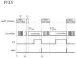
- the generator 42 does not erroneously recognize the stat time point of the period L 1 as the start time point of the start bit in the UART signal (see FIG. 5 ).
- the generator 42 erroneously recognizes the start time point of the period L 1 as the start time point of the start bit in the UART signal.
- the falling edge detector 422 does not detect the time point at which low level appears on the communication bus 3 (see FIG. 1 ) as the start time point of the start bit in the UART communication.
- a filter circuit that can eliminate a low level signal that only lasts for the second predetermined time or shorter can be provided in the falling edge detector 422 .
- the second predetermined time is set to be shorter than the first predetermined time PT 1 described above. More specifically, the second predetermined time is set to be shorter than the low level period of the communication bus 3 (see FIG. 1 ) that corresponds to the start bit in the UART communication. Otherwise, the start time point of the start bit in the UART communication cannot be detected correctly.
- the vehicle X 10 includes display portions X 11 to X 13 .
- the display portion X 11 is provided at the rear left end of the vehicle X 10
- the display portion X 12 is provided in a lower part of a hatchback door X 14 of the vehicle X 10
- the display portion X 13 is provided at the rear right end of the vehicle X 10 .
- the light emitting element circuits 5 A_ 1 to 5 A_ 8 as the display portion X 11
- the light emitting element circuits 5 B_ 1 to 5 B_ 8 and the light emitting element circuits 5 C_ 1 to 5 C_ 8 as the display portion X 12
- the light emitting element circuits 5 D_ 1 to 5 D_ 8 as the display portion X 13
- integral display is possible with the display portions X 11 to X 13 .
Landscapes
- Circuit Arrangement For Electric Light Sources In General (AREA)
- Optical Communication System (AREA)
- Lighting Device Outwards From Vehicle And Optical Signal (AREA)
- Dc Digital Transmission (AREA)
- Engineering & Computer Science (AREA)
- Computer Networks & Wireless Communication (AREA)
Abstract
Description
- Patent Document 1: Japanese Patent Application published as No. 2011-107259.
-
- 1 light emitting system
- 2 microcomputer
- 3 communication bus
- 4A to 4D light emitting element driving device
- 5A_1 to 5A_8 light emitting element circuit
- 5B_1 to 5B_8 light emitting element circuit
- 5C_1 to 5C_8 light emitting element circuit
- 5D_1 to 5D_8 light emitting element circuit
- 6A to 6D DC-DC converter
- 40 terminal
- 41 receiver
- 42 generator
- 421 counter
- 422 falling edge detector
- X10 vehicle
- X11 to X13 display portion
- X14 hatchback door
Claims (15)
Applications Claiming Priority (4)
| Application Number | Priority Date | Filing Date | Title |
|---|---|---|---|
| JP2019221247 | 2019-12-06 | ||
| JP2019221247 | 2019-12-06 | ||
| JP2019-221247 | 2019-12-06 | ||
| PCT/JP2020/032148 WO2021111682A1 (en) | 2019-12-06 | 2020-08-26 | Light-emitting element drive device |
Publications (2)
| Publication Number | Publication Date |
|---|---|
| US20230007757A1 US20230007757A1 (en) | 2023-01-05 |
| US12193129B2 true US12193129B2 (en) | 2025-01-07 |
Family
ID=76221806
Family Applications (1)
| Application Number | Title | Priority Date | Filing Date |
|---|---|---|---|
| US17/781,836 Active 2040-12-16 US12193129B2 (en) | 2019-12-06 | 2020-08-26 | Light emitting element driving device |
Country Status (5)
| Country | Link |
|---|---|
| US (1) | US12193129B2 (en) |
| JP (2) | JP7519381B2 (en) |
| CN (1) | CN114762457B (en) |
| DE (1) | DE112020006004T5 (en) |
| WO (1) | WO2021111682A1 (en) |
Families Citing this family (1)
| Publication number | Priority date | Publication date | Assignee | Title |
|---|---|---|---|---|
| JP7519381B2 (en) * | 2019-12-06 | 2024-07-19 | ローム株式会社 | Light emitting element driving device |
Citations (32)
| Publication number | Priority date | Publication date | Assignee | Title |
|---|---|---|---|---|
| JP2004247856A (en) | 2003-02-12 | 2004-09-02 | Sanyo Electric Co Ltd | Data receiving apparatus and data transmission/ reception method |
| JP2007311190A (en) | 2006-05-18 | 2007-11-29 | Matsushita Electric Works Ltd | Light source lighting device with telecommunication facility |
| US20080094005A1 (en) * | 2006-10-19 | 2008-04-24 | Philips Solid-State Lighting Solutions | Networkable led-based lighting fixtures and methods for powering and controlling same |
| US20080136796A1 (en) * | 2006-11-20 | 2008-06-12 | Philips Solid-State Lighting Solutions | Methods and apparatus for displaying images on a moving display unit |
| US20080164854A1 (en) * | 2007-01-05 | 2008-07-10 | Color Kinetics Incorporated | Methods and apparatus for simulating resistive loads |
| US20090115347A1 (en) * | 2005-06-28 | 2009-05-07 | Rohm Co., Ltd. | Current control circuit, led current control apparatus, and light emitting apparatus |
| JP2011107259A (en) | 2009-11-13 | 2011-06-02 | Panasonic Corp | Light-emitting element drive device |
| US20120262093A1 (en) * | 2011-04-15 | 2012-10-18 | Recker Michael V | Lighting device capable of maintaining light intensity in demand response applications |
| US20130264971A1 (en) * | 2012-03-13 | 2013-10-10 | Verified Energy, Llc | Method of supporting DALI protocol between DALI controllers and devices over an intermediate communication protocol |
| US20130271032A1 (en) * | 2010-12-27 | 2013-10-17 | Inventronics (Hangzhou), Inc. | Device and system for load driving |
| US20140097758A1 (en) * | 2011-10-06 | 2014-04-10 | Michael V. Recker | Wireless lighting device with charging port |
| US20140210342A1 (en) * | 2013-01-25 | 2014-07-31 | Shenzhen Protruly Electronics Co., Ltd | Controlling method and system based on the automotive lighting system illumination angle synchronizing with the automotive speed |
| US20140354345A1 (en) * | 2013-05-30 | 2014-12-04 | Rohm Co., Ltd. | Switch control circuit, switching power supply, and electronic apparatus |
| US9204523B2 (en) * | 2012-05-02 | 2015-12-01 | Express Imaging Systems, Llc | Remotely adjustable solid-state lamp |
| US20160330825A1 (en) * | 2006-03-28 | 2016-11-10 | Wireless Environment, Llc | Cloud connected motion sensor lighting grid |
| US20170101052A1 (en) * | 2015-10-08 | 2017-04-13 | Rohm Co., Ltd. | Apparatus for driving light emitting device |
| US20170223807A1 (en) * | 2006-03-28 | 2017-08-03 | Wireless Environment, Llc. | Cloud connected lighting system |
| US20180035512A1 (en) * | 2016-07-27 | 2018-02-01 | Rohm Co., Ltd. | Semiconductor Device |
| US20180033785A1 (en) * | 2016-07-27 | 2018-02-01 | Rohm Co., Ltd. | Semiconductor device |
| US20180242432A1 (en) * | 2015-02-11 | 2018-08-23 | Philips Lighting Holding B.V. | A lighting system controller |
| US20190037660A1 (en) * | 2017-07-25 | 2019-01-31 | Liteideas, Llc | Smart Dimming System Incorporating a Three-pin Connector |
| US10278244B1 (en) * | 2014-06-18 | 2019-04-30 | Farhad Bahrehmand | Multifunctional universal LED driver |
| US20190226670A1 (en) * | 2016-06-02 | 2019-07-25 | Simon, S.A.U. | Control device |
| US20190357331A1 (en) * | 2018-05-15 | 2019-11-21 | Kuo-Tsun Lin | Operation method of lighting system |
| US20190357330A1 (en) * | 2018-05-15 | 2019-11-21 | Kuo-Tsun Lin | Lighting system |
| US20200275537A1 (en) * | 2019-02-26 | 2020-08-27 | Rohm Co., Ltd. | Light Emitting Device Driving Apparatus, Light Emitting Device Driving System and Light Emitting System |
| US10804725B2 (en) * | 2016-02-26 | 2020-10-13 | Seiko Epson Corporation | Control device, power receiving device, electronic apparatus, and power transmission system |
| US11096253B1 (en) * | 2017-07-05 | 2021-08-17 | Universal Lighting Technologies, Inc. | Method and circuitry to configure multiple drivers simultaneously |
| US20220207777A1 (en) * | 2019-04-30 | 2022-06-30 | Signify Holding B.V. | Luminance distribution determination |
| US20220217828A1 (en) * | 2019-04-30 | 2022-07-07 | Signify Holding B.V. | Camera-based lighting control |
| US20230007757A1 (en) * | 2019-12-06 | 2023-01-05 | Rohm Co., Ltd. | Light emitting element driving device |
| US20230189409A1 (en) * | 2018-07-16 | 2023-06-15 | Jiaxing Super Lighting Electric Appliance Co., Ltd. | Light-emitting diode lamp illumination system, and dimmer and light-emitting diode lamp thereof |
Family Cites Families (9)
| Publication number | Priority date | Publication date | Assignee | Title |
|---|---|---|---|---|
| CN101916547B (en) * | 2010-07-14 | 2012-10-17 | 成都芯源系统有限公司 | Driver for driving a plurality of light emitting elements and display device |
| CN101969721B (en) * | 2010-09-16 | 2013-04-17 | 深圳市明微电子股份有限公司 | Dual-wire data transmission method and device thereof |
| CN102497710B (en) * | 2011-12-30 | 2014-05-28 | 成都芯源系统有限公司 | LED phase-shift dimming circuit and method thereof |
| CN203368812U (en) * | 2013-03-28 | 2013-12-25 | 天津亿达海营照明有限公司 | Wireless DMX light emitting diode (LED) indoor lamp dimming controller |
| CN103561008B (en) * | 2013-10-25 | 2016-11-02 | 深圳市明微电子股份有限公司 | A kind of host-host protocol coding/decoding method, device and host-host protocol decoding chip |
| CN104007756A (en) * | 2014-05-08 | 2014-08-27 | 深圳市元征科技股份有限公司 | Individual car diagnostic system and method based on mobile intelligent terminal |
| CN104965580B (en) * | 2014-05-08 | 2018-10-16 | 腾讯科技(深圳)有限公司 | The methods of exhibiting and device of unread message |
| JP2018029783A (en) * | 2016-08-24 | 2018-03-01 | 株式会社オリンピア | Game machine |
| EP3478031B1 (en) * | 2017-10-30 | 2020-06-24 | Melexis Technologies NV | Bus protocol for dynamic lighting application |
-
2020
- 2020-08-26 JP JP2021562454A patent/JP7519381B2/en active Active
- 2020-08-26 DE DE112020006004.7T patent/DE112020006004T5/en active Pending
- 2020-08-26 CN CN202080083982.9A patent/CN114762457B/en active Active
- 2020-08-26 WO PCT/JP2020/032148 patent/WO2021111682A1/en not_active Ceased
- 2020-08-26 US US17/781,836 patent/US12193129B2/en active Active
-
2024
- 2024-07-08 JP JP2024109431A patent/JP7721747B2/en active Active
Patent Citations (36)
| Publication number | Priority date | Publication date | Assignee | Title |
|---|---|---|---|---|
| JP2004247856A (en) | 2003-02-12 | 2004-09-02 | Sanyo Electric Co Ltd | Data receiving apparatus and data transmission/ reception method |
| US20090115347A1 (en) * | 2005-06-28 | 2009-05-07 | Rohm Co., Ltd. | Current control circuit, led current control apparatus, and light emitting apparatus |
| US20160330825A1 (en) * | 2006-03-28 | 2016-11-10 | Wireless Environment, Llc | Cloud connected motion sensor lighting grid |
| US20170223807A1 (en) * | 2006-03-28 | 2017-08-03 | Wireless Environment, Llc. | Cloud connected lighting system |
| JP2007311190A (en) | 2006-05-18 | 2007-11-29 | Matsushita Electric Works Ltd | Light source lighting device with telecommunication facility |
| US20080094005A1 (en) * | 2006-10-19 | 2008-04-24 | Philips Solid-State Lighting Solutions | Networkable led-based lighting fixtures and methods for powering and controlling same |
| US20080136796A1 (en) * | 2006-11-20 | 2008-06-12 | Philips Solid-State Lighting Solutions | Methods and apparatus for displaying images on a moving display unit |
| US20080164854A1 (en) * | 2007-01-05 | 2008-07-10 | Color Kinetics Incorporated | Methods and apparatus for simulating resistive loads |
| JP2011107259A (en) | 2009-11-13 | 2011-06-02 | Panasonic Corp | Light-emitting element drive device |
| US20130271032A1 (en) * | 2010-12-27 | 2013-10-17 | Inventronics (Hangzhou), Inc. | Device and system for load driving |
| US20120262093A1 (en) * | 2011-04-15 | 2012-10-18 | Recker Michael V | Lighting device capable of maintaining light intensity in demand response applications |
| US20140097758A1 (en) * | 2011-10-06 | 2014-04-10 | Michael V. Recker | Wireless lighting device with charging port |
| US20130264971A1 (en) * | 2012-03-13 | 2013-10-10 | Verified Energy, Llc | Method of supporting DALI protocol between DALI controllers and devices over an intermediate communication protocol |
| US9204523B2 (en) * | 2012-05-02 | 2015-12-01 | Express Imaging Systems, Llc | Remotely adjustable solid-state lamp |
| US20140210342A1 (en) * | 2013-01-25 | 2014-07-31 | Shenzhen Protruly Electronics Co., Ltd | Controlling method and system based on the automotive lighting system illumination angle synchronizing with the automotive speed |
| US20140354345A1 (en) * | 2013-05-30 | 2014-12-04 | Rohm Co., Ltd. | Switch control circuit, switching power supply, and electronic apparatus |
| US10278244B1 (en) * | 2014-06-18 | 2019-04-30 | Farhad Bahrehmand | Multifunctional universal LED driver |
| US20180242432A1 (en) * | 2015-02-11 | 2018-08-23 | Philips Lighting Holding B.V. | A lighting system controller |
| US10285249B2 (en) * | 2015-02-11 | 2019-05-07 | Signify Holding B.V. | Lighting system controller |
| US20170101052A1 (en) * | 2015-10-08 | 2017-04-13 | Rohm Co., Ltd. | Apparatus for driving light emitting device |
| US11901744B2 (en) * | 2016-02-26 | 2024-02-13 | Seiko Epson Corporation | Control device, power receiving device, electronic apparatus, and power transmission system |
| US10804725B2 (en) * | 2016-02-26 | 2020-10-13 | Seiko Epson Corporation | Control device, power receiving device, electronic apparatus, and power transmission system |
| US20210013739A1 (en) * | 2016-02-26 | 2021-01-14 | Seiko Epson Corporation | Control device, power receiving device, electronic apparatus, and power transmission system |
| US20190226670A1 (en) * | 2016-06-02 | 2019-07-25 | Simon, S.A.U. | Control device |
| US10473315B2 (en) * | 2016-06-02 | 2019-11-12 | Simon, S.A.U. | Control device |
| US20180033785A1 (en) * | 2016-07-27 | 2018-02-01 | Rohm Co., Ltd. | Semiconductor device |
| US20180035512A1 (en) * | 2016-07-27 | 2018-02-01 | Rohm Co., Ltd. | Semiconductor Device |
| US11096253B1 (en) * | 2017-07-05 | 2021-08-17 | Universal Lighting Technologies, Inc. | Method and circuitry to configure multiple drivers simultaneously |
| US20190037660A1 (en) * | 2017-07-25 | 2019-01-31 | Liteideas, Llc | Smart Dimming System Incorporating a Three-pin Connector |
| US20190357330A1 (en) * | 2018-05-15 | 2019-11-21 | Kuo-Tsun Lin | Lighting system |
| US20190357331A1 (en) * | 2018-05-15 | 2019-11-21 | Kuo-Tsun Lin | Operation method of lighting system |
| US20230189409A1 (en) * | 2018-07-16 | 2023-06-15 | Jiaxing Super Lighting Electric Appliance Co., Ltd. | Light-emitting diode lamp illumination system, and dimmer and light-emitting diode lamp thereof |
| US20200275537A1 (en) * | 2019-02-26 | 2020-08-27 | Rohm Co., Ltd. | Light Emitting Device Driving Apparatus, Light Emitting Device Driving System and Light Emitting System |
| US20220207777A1 (en) * | 2019-04-30 | 2022-06-30 | Signify Holding B.V. | Luminance distribution determination |
| US20220217828A1 (en) * | 2019-04-30 | 2022-07-07 | Signify Holding B.V. | Camera-based lighting control |
| US20230007757A1 (en) * | 2019-12-06 | 2023-01-05 | Rohm Co., Ltd. | Light emitting element driving device |
Non-Patent Citations (1)
| Title |
|---|
| International Search Report in International Appln. No. PCT/JP2020/032148, dated Oct. 20, 2020, 5 pages (with English Translation). |
Also Published As
| Publication number | Publication date |
|---|---|
| JP7519381B2 (en) | 2024-07-19 |
| US20230007757A1 (en) | 2023-01-05 |
| JP2024124524A (en) | 2024-09-12 |
| DE112020006004T5 (en) | 2022-11-03 |
| JP7721747B2 (en) | 2025-08-12 |
| WO2021111682A1 (en) | 2021-06-10 |
| JPWO2021111682A1 (en) | 2021-06-10 |
| CN114762457B (en) | 2025-09-12 |
| CN114762457A (en) | 2022-07-15 |
Similar Documents
| Publication | Publication Date | Title |
|---|---|---|
| US10081301B2 (en) | Lighting circuit and vehicular turn signal lamp | |
| US8487554B2 (en) | Illumination device comprising multiple LEDs | |
| US8493004B2 (en) | Ilumination device comprising multiple LEDs | |
| US9801243B2 (en) | Lighting system with a plurality of LEDs | |
| US8810162B2 (en) | Low cost LED driver with improved serial bus | |
| US8659514B2 (en) | LED matrix driver ghost image prevention apparatus and method | |
| US20050269580A1 (en) | Single wire serial protocol for RGB LED drivers | |
| EP2482620A1 (en) | Light-emitting module device, light-emitting module used in the device, and lighting apparatus provided with the device | |
| CN107110464B (en) | Light control device | |
| TWI458216B (en) | Light emitting diode luminance system having clamping device | |
| US12193129B2 (en) | Light emitting element driving device | |
| US20130241410A1 (en) | Control device for lighting led and detecting breakage thereof | |
| US11924941B2 (en) | Light emission control system, light emission system, light emission control device, and light emission device | |
| WO2012086790A1 (en) | Two-terminal led light-emitting device, and led illumination device provided with same | |
| CN112188666B (en) | A multi-LED driving and multi-button pin multiplexing circuit and control method thereof | |
| CN214381497U (en) | A digital LED module that can be arbitrarily serial-parallel | |
| CN110730536B (en) | Colour lamp device controlled by power line edge signal | |
| US20220232684A1 (en) | Light-emitting circuit, light-emitting system, and control method | |
| JP6472123B2 (en) | Handrail lighting system and LED unit | |
| US9572214B1 (en) | Light emitting diode lamp string driving system | |
| JP2006172819A (en) | Lighting control circuit for vehicular lamp | |
| CN114241986B (en) | Display assembly, display panel and control method of display assembly | |
| US12490362B1 (en) | Multi-modulation string light | |
| JP6472122B2 (en) | Handrail lighting system and LED unit | |
| KR101618818B1 (en) | Light emitting element driving circuit and driving method therefor |
Legal Events
| Date | Code | Title | Description |
|---|---|---|---|
| FEPP | Fee payment procedure |
Free format text: ENTITY STATUS SET TO UNDISCOUNTED (ORIGINAL EVENT CODE: BIG.); ENTITY STATUS OF PATENT OWNER: LARGE ENTITY |
|
| AS | Assignment |
Owner name: ROHM CO., LTD., JAPAN Free format text: ASSIGNMENT OF ASSIGNORS INTEREST;ASSIGNOR:NAGAO, KEI;REEL/FRAME:060094/0939 Effective date: 20220418 |
|
| STPP | Information on status: patent application and granting procedure in general |
Free format text: DOCKETED NEW CASE - READY FOR EXAMINATION |
|
| STPP | Information on status: patent application and granting procedure in general |
Free format text: NON FINAL ACTION MAILED |
|
| STPP | Information on status: patent application and granting procedure in general |
Free format text: RESPONSE TO NON-FINAL OFFICE ACTION ENTERED AND FORWARDED TO EXAMINER |
|
| STPP | Information on status: patent application and granting procedure in general |
Free format text: NOTICE OF ALLOWANCE MAILED -- APPLICATION RECEIVED IN OFFICE OF PUBLICATIONS |
|
| STPP | Information on status: patent application and granting procedure in general |
Free format text: DOCKETED NEW CASE - READY FOR EXAMINATION |
|
| STPP | Information on status: patent application and granting procedure in general |
Free format text: NOTICE OF ALLOWANCE MAILED -- APPLICATION RECEIVED IN OFFICE OF PUBLICATIONS |
|
| STPP | Information on status: patent application and granting procedure in general |
Free format text: AWAITING TC RESP, ISSUE FEE PAYMENT VERIFIED |
|
| STPP | Information on status: patent application and granting procedure in general |
Free format text: PUBLICATIONS -- ISSUE FEE PAYMENT VERIFIED |
|
| STCF | Information on status: patent grant |
Free format text: PATENTED CASE |