US12187044B2 - Ink container - Google Patents
Ink container Download PDFInfo
- Publication number
- US12187044B2 US12187044B2 US18/163,639 US202318163639A US12187044B2 US 12187044 B2 US12187044 B2 US 12187044B2 US 202318163639 A US202318163639 A US 202318163639A US 12187044 B2 US12187044 B2 US 12187044B2
- Authority
- US
- United States
- Prior art keywords
- holding member
- supply
- supply tube
- indication
- ink
- Prior art date
- Legal status (The legal status is an assumption and is not a legal conclusion. Google has not performed a legal analysis and makes no representation as to the accuracy of the status listed.)
- Active, expires
Links
- 238000007789 sealing Methods 0.000 claims abstract description 57
- 238000003860 storage Methods 0.000 claims abstract description 24
- 239000000976 ink Substances 0.000 description 94
- 230000001105 regulatory effect Effects 0.000 description 24
- 238000003825 pressing Methods 0.000 description 18
- 230000004048 modification Effects 0.000 description 12
- 238000012986 modification Methods 0.000 description 12
- 238000003780 insertion Methods 0.000 description 9
- 230000037431 insertion Effects 0.000 description 9
- 230000008878 coupling Effects 0.000 description 8
- 238000010168 coupling process Methods 0.000 description 8
- 238000005859 coupling reaction Methods 0.000 description 8
- 239000003086 colorant Substances 0.000 description 6
- 238000004519 manufacturing process Methods 0.000 description 4
- 239000013013 elastic material Substances 0.000 description 2
- 238000000034 method Methods 0.000 description 2
- 239000011347 resin Substances 0.000 description 2
- 229920005989 resin Polymers 0.000 description 2
- 230000008859 change Effects 0.000 description 1
- 238000005520 cutting process Methods 0.000 description 1
- 230000005484 gravity Effects 0.000 description 1
- 239000012943 hotmelt Substances 0.000 description 1
- 239000007788 liquid Substances 0.000 description 1
- 239000000463 material Substances 0.000 description 1
- 230000007246 mechanism Effects 0.000 description 1
- 238000002844 melting Methods 0.000 description 1
- 230000008018 melting Effects 0.000 description 1
- 239000002923 metal particle Substances 0.000 description 1
- 239000000203 mixture Substances 0.000 description 1
- 239000002245 particle Substances 0.000 description 1
- 239000000049 pigment Substances 0.000 description 1
- 239000002994 raw material Substances 0.000 description 1
- 230000004044 response Effects 0.000 description 1
- 239000011343 solid material Substances 0.000 description 1
- 239000002904 solvent Substances 0.000 description 1
- 238000002834 transmittance Methods 0.000 description 1
- 238000011144 upstream manufacturing Methods 0.000 description 1
- XLYOFNOQVPJJNP-UHFFFAOYSA-N water Substances O XLYOFNOQVPJJNP-UHFFFAOYSA-N 0.000 description 1
- 238000003466 welding Methods 0.000 description 1
Images


Classifications
-
- B—PERFORMING OPERATIONS; TRANSPORTING
- B41—PRINTING; LINING MACHINES; TYPEWRITERS; STAMPS
- B41J—TYPEWRITERS; SELECTIVE PRINTING MECHANISMS, i.e. MECHANISMS PRINTING OTHERWISE THAN FROM A FORME; CORRECTION OF TYPOGRAPHICAL ERRORS
- B41J2/00—Typewriters or selective printing mechanisms characterised by the printing or marking process for which they are designed
- B41J2/005—Typewriters or selective printing mechanisms characterised by the printing or marking process for which they are designed characterised by bringing liquid or particles selectively into contact with a printing material
- B41J2/01—Ink jet
- B41J2/17—Ink jet characterised by ink handling
- B41J2/175—Ink supply systems ; Circuit parts therefor
- B41J2/17503—Ink cartridges
- B41J2/17536—Protection of cartridges or parts thereof, e.g. tape
-
- B—PERFORMING OPERATIONS; TRANSPORTING
- B41—PRINTING; LINING MACHINES; TYPEWRITERS; STAMPS
- B41J—TYPEWRITERS; SELECTIVE PRINTING MECHANISMS, i.e. MECHANISMS PRINTING OTHERWISE THAN FROM A FORME; CORRECTION OF TYPOGRAPHICAL ERRORS
- B41J2/00—Typewriters or selective printing mechanisms characterised by the printing or marking process for which they are designed
- B41J2/005—Typewriters or selective printing mechanisms characterised by the printing or marking process for which they are designed characterised by bringing liquid or particles selectively into contact with a printing material
- B41J2/01—Ink jet
- B41J2/17—Ink jet characterised by ink handling
- B41J2/175—Ink supply systems ; Circuit parts therefor
- B41J2/17503—Ink cartridges
- B41J2/17506—Refilling of the cartridge
- B41J2/17509—Whilst mounted in the printer
-
- B—PERFORMING OPERATIONS; TRANSPORTING
- B41—PRINTING; LINING MACHINES; TYPEWRITERS; STAMPS
- B41J—TYPEWRITERS; SELECTIVE PRINTING MECHANISMS, i.e. MECHANISMS PRINTING OTHERWISE THAN FROM A FORME; CORRECTION OF TYPOGRAPHICAL ERRORS
- B41J2/00—Typewriters or selective printing mechanisms characterised by the printing or marking process for which they are designed
- B41J2/005—Typewriters or selective printing mechanisms characterised by the printing or marking process for which they are designed characterised by bringing liquid or particles selectively into contact with a printing material
- B41J2/01—Ink jet
- B41J2/17—Ink jet characterised by ink handling
- B41J2/175—Ink supply systems ; Circuit parts therefor
- B41J2/17503—Ink cartridges
- B41J2/17513—Inner structure
-
- B—PERFORMING OPERATIONS; TRANSPORTING
- B41—PRINTING; LINING MACHINES; TYPEWRITERS; STAMPS
- B41J—TYPEWRITERS; SELECTIVE PRINTING MECHANISMS, i.e. MECHANISMS PRINTING OTHERWISE THAN FROM A FORME; CORRECTION OF TYPOGRAPHICAL ERRORS
- B41J2/00—Typewriters or selective printing mechanisms characterised by the printing or marking process for which they are designed
- B41J2/005—Typewriters or selective printing mechanisms characterised by the printing or marking process for which they are designed characterised by bringing liquid or particles selectively into contact with a printing material
- B41J2/01—Ink jet
- B41J2/17—Ink jet characterised by ink handling
- B41J2/175—Ink supply systems ; Circuit parts therefor
- B41J2/17503—Ink cartridges
- B41J2/1752—Mounting within the printer
- B41J2/17523—Ink connection
-
- B—PERFORMING OPERATIONS; TRANSPORTING
- B41—PRINTING; LINING MACHINES; TYPEWRITERS; STAMPS
- B41J—TYPEWRITERS; SELECTIVE PRINTING MECHANISMS, i.e. MECHANISMS PRINTING OTHERWISE THAN FROM A FORME; CORRECTION OF TYPOGRAPHICAL ERRORS
- B41J2/00—Typewriters or selective printing mechanisms characterised by the printing or marking process for which they are designed
- B41J2/005—Typewriters or selective printing mechanisms characterised by the printing or marking process for which they are designed characterised by bringing liquid or particles selectively into contact with a printing material
- B41J2/01—Ink jet
- B41J2/17—Ink jet characterised by ink handling
- B41J2/175—Ink supply systems ; Circuit parts therefor
- B41J2/17503—Ink cartridges
- B41J2/17543—Cartridge presence detection or type identification
- B41J2/17546—Cartridge presence detection or type identification electronically
-
- B—PERFORMING OPERATIONS; TRANSPORTING
- B41—PRINTING; LINING MACHINES; TYPEWRITERS; STAMPS
- B41J—TYPEWRITERS; SELECTIVE PRINTING MECHANISMS, i.e. MECHANISMS PRINTING OTHERWISE THAN FROM A FORME; CORRECTION OF TYPOGRAPHICAL ERRORS
- B41J2/00—Typewriters or selective printing mechanisms characterised by the printing or marking process for which they are designed
- B41J2/005—Typewriters or selective printing mechanisms characterised by the printing or marking process for which they are designed characterised by bringing liquid or particles selectively into contact with a printing material
- B41J2/01—Ink jet
- B41J2/17—Ink jet characterised by ink handling
- B41J2/175—Ink supply systems ; Circuit parts therefor
- B41J2/17503—Ink cartridges
- B41J2/17553—Outer structure
-
- Y—GENERAL TAGGING OF NEW TECHNOLOGICAL DEVELOPMENTS; GENERAL TAGGING OF CROSS-SECTIONAL TECHNOLOGIES SPANNING OVER SEVERAL SECTIONS OF THE IPC; TECHNICAL SUBJECTS COVERED BY FORMER USPC CROSS-REFERENCE ART COLLECTIONS [XRACs] AND DIGESTS
- Y02—TECHNOLOGIES OR APPLICATIONS FOR MITIGATION OR ADAPTATION AGAINST CLIMATE CHANGE
- Y02W—CLIMATE CHANGE MITIGATION TECHNOLOGIES RELATED TO WASTEWATER TREATMENT OR WASTE MANAGEMENT
- Y02W30/00—Technologies for solid waste management
- Y02W30/50—Reuse, recycling or recovery technologies
- Y02W30/80—Packaging reuse or recycling, e.g. of multilayer packaging
Definitions
- the present disclosure relates to an ink container that stores an ink.
- JP-A-2021-28120 An example of ink containers is described in, for example, JP-A-2021-28120, which describes a cartridge.
- This cartridge includes a container pack, which is an example storage section for storing an ink, a supply member for supplying the liquid in the container pack to the outside, and a holding member detachably attached to the supply member.
- the supply member includes a supply tube, a valve element, a sealing member, and a pressing member.
- the pressing member presses the valve element against the sealing member.
- the holding member holds the sealing member from the side opposite to the pressing member.
- the holding member and the supply member in JP-A-2021-28120 each have a screw mechanism that engage each other. Accordingly, to attach the holding member to the supply member or detach the holding member from the supply member, the holding member has to be rotated multiple times about the supply member, and thus the holding member is unsuitable for refilling. Even if the product has been refilled, the refilled product cannot be distinguished from other products that have not been refilled, and thus users may not recognize that this product is an environmentally friendly refilled product.
- An ink container to solve the above-described problem includes a storage section configured to store an ink, a supply tube configured to supply the ink stored in the storage section to a printer, a sealing member disposed in the supply tube, and a holding member configured to hold the sealing member.
- the holding member is detachably attached to the supply tube and has an indication that indicates that a refilling operation has been performed.
- FIG. 1 is a schematic view illustrating an ink container according to an embodiment, the ink container attached to a printer.
- FIG. 2 is a bottom view illustrating an ink container.
- FIG. 3 is a plan view illustrating a supply member with a holding member in a moving position.
- FIG. 4 is a side view of a supply member.
- FIG. 5 is a plan view illustrating a supply member with a holding member in an attachment position.
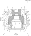
- FIG. 6 is a cross-sectional view taken along line VI-VI in FIG. 4 .
- FIG. 7 is an enlarged view of the holding member illustrated in FIG. 6 .
- FIG. 8 is a perspective view illustrating a holding member and a supply tube.
- FIG. 9 is a cross-sectional view taken along line IX-IX in FIG. 4 .
- FIG. 10 is a perspective view illustrating a supply tube.
- FIG. 11 is a cross-sectional view taken along line XI-XI in FIG. 3 .
- FIG. 12 is a cross-sectional view taken along line XII-XII in FIG. 5 .
- FIG. 13 is a plan view illustrating a supply tube.
- FIG. 14 is a plan view illustrating a holding member according to a first modification.
- FIG. 15 is a plan view illustrating a holding member according to a first modification.
- FIG. 16 is a plan view illustrating a holding member according to a second modification.
- FIG. 17 is a plan view illustrating a holding member according to a second modification.
- the ink container is attached to a printer.
- the printer is, for example, an ink jet printer that performs printing by ejecting an ink onto a paper sheet, which is an example medium.
- a printer 11 is installed on a horizontal plane, and the Z-axis denotes the direction of gravity and the X-axis and the Y-axis denote directions along the horizontal plane.
- the X-axis, the Y-axis, and the Z-axis are orthogonal to each other.
- the printer 11 may include a casing 12 and an operation panel 13 .
- the operation panel 13 is used by users to operate the printer 11 .
- the operation panel 13 may include a touch panel and/or may include buttons (not illustrated).
- the printer 11 may include a container 15 , an attachment section 16 , a front cover 17 , a medium storage section 18 , a discharge tray 19 , a print head 20 , and a carriage 21 .
- the container 15 is detachably attached to the attachment section 16 .
- the container 15 holds an ink container 23 .
- the ink container 23 is attachable to and detachable from the container 15 that has been detached from the attachment section 16 . Attaching the container 15 to the attachment section 16 enables the ink in the ink container 23 held by the container 15 to be supplied to the printer 11 .
- the printer 11 may include one or more containers 15 .
- Ink may be supplied to the printer 11 from a plurality of ink containers 23 .
- the ink containers 23 may be held in one container 15 or in a plurality of containers 15 .
- the printer 11 according to the embodiment includes four containers 15 , and each container 15 holds one ink container 23 .
- the ink containers 23 may store different inks. For example, different inks may be inks of different colors such as black, cyan, magenta, and yellow.
- the front cover 17 is openable and closable, for example, by being rotated.
- the front cover 17 that is in a closed position illustrated in FIG. 1 covers the attachment section 16 and the containers 15 attached to the attachment section 16 .
- the front cover 17 is moved to an open position (not illustrated), the attachment section 16 and the containers 15 are exposed and the container 15 can be attached and detached.
- the medium storage section 18 stores sheets of a medium 25 .
- the carriage 21 holds the print head 20 in a movable manner.
- the print head 20 while being moved, performs printing by ejecting an ink onto the medium 25 supplied from the medium storage section 18 .
- the printed medium 25 is discharged onto the discharge tray 19 .
- the printer 11 may include a supply needle 27 as illustrated in FIG. 2 .
- the printer 11 according to the embodiment includes the same number of supply needles 27 as the number of the ink containers 23 , which are attachable to one or more containers 15 .
- the supply needle 27 is disposed at the back of the attachment section 16 . When the supply needle 27 is inserted into the ink container 23 attached to the attachment section 16 , the ink in the ink container 23 is supplied to the outside.
- the X-axis, the Y-axis, and the Z-axis are provided with reference to the orientation of the ink containers 23 attached to the printer 11 .
- the ink container 23 includes a storage section 29 and a supply member 30 as illustrated in FIG. 2 .
- the ink container 23 may include a supporting member 31 .
- the storage section 29 stores an ink.
- the storage section 29 according to the embodiment is a pouch comprising a plurality of film members.
- the storage section 29 may be formed by bonding four sides of two sheets of rectangular film members.
- the storage section 29 may have a gusset.
- the supply member 30 according to the embodiment is attached to the storage section 29 such that the supply member 30 is held between two film members.
- the supporting member 31 supports the supply member 30 .
- the supporting member 31 may include one or more cylinders 33 and one or more hook portions 34 .
- the supporting member 31 according to the embodiment includes two cylinders 33 , that is, a circular cylinder 33 and an elliptic cylinder 33 .
- the cylinders 33 are inserted into positioning holes 35 in the supply member 30 to position the supply member 30 and the supporting member 31 .
- the supporting member 31 according to the embodiment includes three hook portions 34 . These three hook portions 34 hold the positioned supply member 30 such that the supply member 30 is caught from three sides.
- the supply member 30 includes a supply tube 37 and a holding member 38 as illustrated in FIG. 3 .
- the holding member 38 is detachably attached to the supply tube 37 .
- the holding member 38 is movable in an attachment direction AD and a detachment direction WD. More specifically, the holding member 38 that is in a moving position MP with respect to the supply tube 37 illustrated in FIG. 3 is movable in the attachment direction AD and the detachment direction WD.
- the attachment direction AD is a direction in which the holding member 38 that has been detached from the supply tube 37 moves toward the supply tube 37 .
- the holding member 38 that has been detached from the supply tube 37 is moved in the attachment direction AD and attached to the supply tube 37 .
- the detachment direction WD is opposite to the attachment direction AD.
- the detachment direction WD is a direction in which the holding member 38 is detached from the supply tube 37 .
- the holding member 38 that has been attached to the supply tube 37 is moved in the detachment direction WD and detached from the supply tube 37 .
- the attachment direction AD and the detachment direction WD according to the embodiment are parallel to the Y-axis.
- the holding member 38 is rotatable in a first circumferential direction D1 or a second circumferential direction D2 in a state in which the holding member 38 is attached to the supply tube 37 , as illustrated in FIG. 4 .
- the first circumferential direction D1 is the clockwise direction in FIG. 4 .
- the second circumferential direction D2 is the counterclockwise direction in FIG. 4 .
- the second circumferential direction D2 is opposite to the first circumferential direction D1.
- the holding member 38 is rotated in the first circumferential direction D1 from the moving position MP in FIG. 3 to the attachment position AP in FIG. 5 , as illustrated in FIG. 3 and FIG. 5 .
- the holding member 38 is rotated in the second circumferential direction D2 from the attachment position AP in FIG. 5 to the moving position MP in FIG. 3 .
- the angle of rotation of the holding member 38 is less than 360 degrees.
- the angle of rotation of the holding member 38 may be less than 180 degrees.
- the holding member 38 may be switched between the moving position MP and the attachment position AP within one complete rotation or a half rotation of the holding member 38 .
- the holding member 38 according to the embodiment is switched between the moving position MP and the attachment position AP when the holding member 38 is rotated by about 45 degrees.
- the supply member 30 includes a sealing member 40 as illustrated in FIG. 6 .
- the supply member 30 may include a valve element 41 and a pressing member 42 .
- the supply member 30 may include a supply path 43 , a supply port 44 , a first support surface 45 , and a second support surface 46 .
- the supply port 44 is open at a tip 37 t of the supply tube 37 .
- the supply path 43 is a flow path through which an ink flows in the supply tube 37 .
- An upstream end of the supply path 43 communicates with the inside of the storage section 29 .
- the supply port 44 is a downstream end of the supply path 43 and communicates with the supply path 43 .
- the first support surface 45 supports the sealing member 40 .
- the first support surface 45 is provided in the supply tube 37 .
- the first support surface 45 is provided in the supply path 43 .
- the second support surface 46 supports the pressing member 42 .
- the second support surface 46 is provided in the supply tube 37 .
- the second support surface 46 is provided in the supply path 43 .
- the sealing member 40 , the valve element 41 , and the pressing member 42 are disposed in the supply tube 37 .
- the sealing member 40 , the valve element 41 , and the pressing member 42 are disposed in the middle of the supply path 43 .
- the sealing member 40 according to the embodiment is disposed between the valve element 41 and the holding member 38 .
- the valve element 41 is made of, for example, an elastic material.
- the valve element 41 according to the embodiment is made of rubber.
- the pressing member 42 presses the valve element 41 to press the valve element 42 against the sealing member 40 .
- the pressing member 42 includes, for example, a spring.
- the sealing member 40 may have a first sealing end 40 f , a second sealing end 40 s , and an insertion hole 48 as illustrated in FIG. 7 .
- the first sealing end 40 f is an end portion of the sealing member 40 and is in contact with the first support surface 45 .
- the second sealing end 40 s is an end portion opposite to the first sealing end 40 f in the sealing member 40 .
- the first sealing end 40 f of the sealing member 40 is configured to be in contact with the valve element 41 .
- the sealing member 40 comes into contact with the valve element 41 to block the supply tube 37 .
- the sealing member 40 blocks the supply tube 37 , thereby suppressing leakage of the ink from the supply tube 37 from occurring.
- the sealing member 40 is made of, for example, an elastic material.
- the sealing member 40 according to the embodiment is made of rubber.
- the insertion hole 48 is a hole into which the supply needle 27 is inserted.
- the insertion hole 48 extends through the sealing member 40 from the first sealing end 40 f to the second sealing end 40 s . Accordingly, the sealing member 40 has a tubular shape.
- a minimum inner diameter of the insertion hole 48 is smaller than an outer diameter of the supply needle 27 .
- the sealing member 40 is in contact with the inserted supply needle 27 .
- the valve element 41 moves away from the sealing member 40 , thereby enabling the sealing member 40 and the valve element 41 to release the blockage of the supply tube 37 .
- the ink can be supplied from the storage section 29 to the printer 11 through the supply tube 37 and the supply needle 27 .
- the holding member 38 holds the sealing member 40 as illustrated in FIG. 7 .
- the holding member 38 is attached to the supply tube 37 to hold the sealing member 40 .
- the holding member 38 according to the embodiment holds the sealing member 40 from the second sealing end 40 s .
- the holding member 38 is made of, for example, resin.
- the holding member 38 may include an external cylinder 50 , an internal cylinder 51 , and a coupling section 52 .
- one end of the external cylinder 50 in the attachment direction AD is referred to as a first outer end 50 f and the other end is referred to as a second outer end 50 s .
- one end of the internal cylinder 51 in the attachment direction AD is referred to as a first inner end 51 f and the other end is referred to as a second inner end 51 s .
- the first inner end 51 f and the second outer end 50 s according to the embodiment are also ends of the holding member 38 .
- the coupling section 52 couples the external cylinder 50 and the internal cylinder 51 . More specifically, the coupling section 52 couples the first outer end 50 f of the external cylinder 50 and a central portion of the internal cylinder 51 in the attachment direction AD.
- the holding member 38 may include a supply hole 54 defined by the internal cylinder 51 .
- the supply hole 54 is a hole into which the supply needle 27 is inserted. When the ink container 23 is attached to the attachment section 16 , the supply needle 27 is inserted into the supply hole 54 .
- the internal cylinder 51 enters the insertion hole 48 from the second sealing end 40 s .
- the second inner end 51 s of the internal cylinder 51 comes into contact with the inner circumferential surface of the insertion hole 48 .
- the holding member 38 holds the sealing member 40 such that the internal cylinder 51 presses and widens the sealing member 40 , thereby pressing the sealing member 40 against the supply tube 37 .
- the external cylinder 50 is located outside the supply tube 37 in a state in which the holding member 38 is attached to the supply tube 37 .
- the holding member 38 holds the supply tube 37 and the sealing member 40 in the radial direction by using the external cylinder 50 and the internal cylinder 51 .
- the radial direction according to the embodiment is a radial direction with respect to a central axis A of the supply tube 37 .
- the central axis A according to the embodiment is parallel to the Y-axis.
- the holding member 38 may have an opening 56 , a notch 57 , and a convex portion 58 as illustrated in FIG. 8 .
- the holding member 38 may have one or more openings 56 , one or more notches 57 , and one or more convex portions 58 .
- the holding member 38 according to the embodiment has four openings 56 , four notches 57 , and four convex portions 58 .
- the four openings 56 are equally spaced in the first circumferential direction D1.
- Each opening 56 is provided at least in the coupling section 52 and extends through the coupling section 52 .
- the openings 56 according to the embodiment extend through the coupling section 52 and the external cylinder 50 .
- the four openings 56 according to the embodiment divide the coupling section 52 into four.
- Each opening 56 has a first surface 56 f and a second surface 56 s that are aligned in the first circumferential direction D1 and face each other; that is, the holding member 38 according to the embodiment has a plurality of first surfaces 56 f and a plurality of second surfaces 56 s .
- the first surfaces 56 f face in the first circumferential direction D1.
- the second surfaces 56 s face in the second circumferential direction D2.
- the notches 57 are formed in the external cylinder 50 .
- the notches 57 are recessed from the second outer end 50 s in the detachment direction WD.
- the notches 57 enable the external cylinder 50 to elastically deform.
- the notches 57 according to the embodiment are located between the openings 56 in the first circumferential direction D1.
- the convex portions 58 are formed in the internal cylinder 51 .
- the convex portions 58 protrude outward from the first inner end 51 f in the radial direction.
- the convex portions 58 are provided at the same positions as the openings 56 in the first circumferential direction D1. In other words, the convex portions 58 and the openings 56 are aligned in the attachment direction AD.
- the convex portion 58 has a third surface 58 t as illustrated in FIG. 9 .
- the third surface 58 t faces in the attachment direction AD.
- the third surface 58 t is located between the first inner end 51 f and the opening 56 in the attachment direction AD; that is, the third surface 58 t is located between the first surface 56 f and the first inner end 51 f .
- the third surface 58 t is located between the second surface 56 s and the first inner end 51 f.
- the holding member 38 has a protrusion 60 that comes into contact with the supply tube 37 .
- the holding member 38 may include one or more protrusions 60 .
- the protrusions 60 may be equally spaced in the first circumferential direction D1.
- the holding member 38 according to the embodiment includes four protrusions 60 .
- the protrusions 60 may be provided in the second outer end 50 s .
- the protrusions 60 protrude inward from the external cylinder 50 .
- the protrusions 60 are provided between the notches 57 arranged in the first circumferential direction D1.
- at least part of one opening 56 , at least part of one convex portion 58 , and at least part of one protrusion 60 are located at the same position in the first circumferential direction D1.
- the convex portion 58 , the opening 56 , and the protrusion 60 are aligned in the attachment direction AD.
- the supply tube 37 has an outer surface 62 as illustrated in FIG. 10 .
- the outer surface 62 may have a first outer surface 62 a , a second outer surface 62 b , a third outer surface 62 c , a fourth outer surface 62 d , and a fifth outer surface 62 e.
- the supply tube 37 has one or more guide portions 64 and one or more stop portions 65 .
- the supply tube 37 may have one or more regulating sections 66 .
- the regulating section 66 may have a first rib 68 and a second rib 69 .
- the supply tube 37 may have one or more recesses 70 .
- the guide portion 64 and the stop portion 65 are aligned in the first circumferential direction D1 in the outer surface 62 of the supply tube 37 .
- One guide portion 64 and one stop portion 65 may be provided per regulating section 66 .
- the guide portion 64 , the stop portion 65 , the regulating section 66 , and the recess 70 are provided in the outer surface 62 .
- the regulating section 66 is a concave portion formed at a position away from the tip 37 t of the supply tube 37 in the attachment direction AD.
- the supply tube 37 may have a plurality of regulating sections 66 .
- the supply tube 37 according to the embodiment has two guide portions 64 , two stop portions 65 , two regulating sections 66 , and two recesses 70 .
- the regulating sections 66 and the recesses 70 are provided alternately in the first circumferential direction D1.
- the first outer surface 62 a is an outer surface of the regulating section 66 and the recess 70 .
- the second outer surface 62 b , the third outer surface 62 c , and the fourth outer surface 62 d are inner surfaces of the regulating section 66 .
- the fifth outer surface 62 e is an inner surface of the recess 70 .
- the fifth outer surface 62 e may be a curved surface.
- the second outer surface 62 b , the third outer surface 62 c , and the fourth outer surface 62 d are aligned in the first circumferential direction D1.
- the first outer surface 62 a , the second outer surface 62 b , the third outer surface 62 c , and the fourth outer surface 62 d are located differently in the radial direction.
- the first outer surface 62 a is the outermost surface.
- the fourth outer surface 62 d is the innermost surface.
- the fourth outer surface 62 d is away from the first outer surface 62 a in the radial direction compared with the second outer surface 62 b and the third outer surface 62 c .
- the second outer surface 62 b is located between the first outer surface 62 a and the fourth outer surface 62 d in the radial direction.
- the third outer surface 62 c couples the second outer surface 62 b and the fourth outer surface 62 d .
- the third outer surface 62 c is tilted with respect to the first circumferential direction D1.
- the first rib 68 according to the embodiment is a step between the first outer surface 62 a and the second outer surface 62 b in the first circumferential direction D1.
- the second rib 69 according to the embodiment is a step between the fourth outer surface 62 d and the first outer surface 62 a in the first circumferential direction D1.
- Each of the first rib 68 and the second rib 69 according to the embodiment has a surface substantially vertical with respect to the first outer surface 62 a .
- the first rib 68 is located at one end of the regulating section 66 and the second rib 69 is located at the other end of the regulating section 66 in the first circumferential direction D1.
- the guide portion 64 guides the movement of the protrusion 60 in the attachment direction AD and the detachment direction WD.
- the guide portion 64 may have a guide surface 71 and a guide wall 72 .
- the guide surface 71 is located in the detachment direction WD with respect to the second outer surface 62 b .
- the guide surface 71 couples the first outer surface 62 a and the second outer surface 62 b .
- the guide surface 71 is tilted with respect to the central axis A.
- the guide surface 71 forms obtuse angles with respect to the first outer surface 62 a and the second outer surface 62 b .
- one guide portion 64 has one guide surface 71 and two guide walls 72 .
- the two guide walls 72 are disposed at respective ends of the guide surface 71 in the first circumferential direction D1.
- One guide wall 72 of the two guide walls 72 may have the same plane as the first rib 68 .
- the stop portion 65 according to the embodiment is a step between the fourth outer surface 62 d and the first outer surface 62 a in the detachment direction WD.
- the stop portion 65 is located in the detachment direction WD with respect to the fourth outer surface 62 d .
- the stop portion 65 according to the embodiment has a surface substantially vertical with respect to the first outer surface 62 a.
- the regulating section 66 regulates the moving range of the protrusion 60 in the first circumferential direction D1 to a range from a first position P1 in FIG. 11 to a second position P2 in FIG. 12 .
- the first rib 68 comes into contact with the protrusion 60 located in the first position P1 and regulates the movement of the protrusion 60 in the second circumferential direction D2.
- the protrusion 60 located in the regulating section 66 is located in the first position P1.
- the second rib 69 comes into contact with the protrusion 60 located in the second position P2 and regulates the movement of the protrusion 60 in the first circumferential direction D1.
- the protrusion 60 located in the regulating section 66 is located in the second position P2.
- the protrusion 60 that is located in the first position P1 and the guide portion 64 are aligned in the detachment direction WD as illustrated in FIG. 13 .
- the protrusion 60 that is located in the second position P2 and the stop portion 65 are aligned in the detachment direction WD.
- the stop portion 65 comes into contact with the protrusion 60 to regulate the movement of the holding member 38 in the detachment direction WD as illustrated in FIG. 9 .
- the ink container 23 can be refilled. Refilling in this embodiment means filling a used ink container 23 with ink. An ink container 23 used by a user is collected and refilled by a technician. The refilled ink container 23 is used by the user or another person.
- At least one of the holding member 38 , the sealing member 40 , the valve element 41 , and the pressing member 42 of the ink container 23 as illustrated in FIG. 6 may be replaced. Such part replacement may be performed at the time of refilling. To replace a part, first the holding member 38 is detached from the supply tube 37 .
- the holding member 38 before the detachment operation is in the attachment position AP as illustrated in FIG. 5 .
- the technician moves a jig (not illustrated) in the attachment direction AD to align the jig to the opening 56 .
- the jig is turned in the second circumferential direction D2 and the jig presses the first surface 56 f , thereby turning the holding member 38 in the second circumferential direction D2.
- the jig according to the embodiment is turned by about 45 degrees to change the position of the holding member 38 from the attachment position AP to the moving position MP.
- two protrusions 60 of the four protrusions 60 are located within the regulating sections 66 , and the other two protrusions 60 are located within the recesses 70 .
- the two protrusions 60 of the holding member 38 in the regulating sections 66 come into contact with the first ribs 68 , regulating the turn in the second circumferential direction D2. Accordingly, the two protrusions 60 in the regulating sections 66 are located in the first positions P1 and are aligned with the guide portions 64 in the detachment direction WD.
- the jig presses the third surface 58 t in the detachment direction WD as illustrated in FIG. 3 . More specifically, the jig moves in the detachment direction WD in the state in which part of the jig is aligned with the third surface 58 t , and thereby the holding member 38 is detached from the supply tube 37 . In this operation, the protrusion 60 in the first position P1 is moved from the second outer surface 62 b to run on the first outer surface 62 a via the guide portion 64 .
- the sealing member 40 , the valve element 41 , and the pressing member 42 can be removed via the supply port 44 . All or some of the holding member 38 , the sealing member 40 , the valve element 41 , and the pressing member 42 may be replaced.
- the jig is moved in the attachment direction AD with the jig holding the holding member 38 .
- the jig may hold the convex portion 58 .
- the jig attaches the holding member 38 , which is in the moving position MP with respect to the supply tube 37 , to the supply tube 37 .
- two protrusions 60 of the four protrusions 60 pass the guiding sections 64 and enter the regulating sections 66 as illustrated in FIG. 11 .
- the other two protrusions 60 move along the first outer surfaces 62 a and move across the recesses 70 .
- the jig turns in the first circumferential direction D1 as illustrated in FIG. 3 .
- the jig turning in the first circumferential direction D1 presses the second surface 56 s , thereby turning the holding member 38 in the first circumferential direction D1.
- the jig according to the embodiment is turned by about 45 degrees to switch the position of the holding member 38 from the moving position MP to the attachment position AP.
- the two protrusions of the holding member 38 in the regulating sections 66 come into contact with the second ribs 69 , regulating the turn in the first circumferential direction D1 as illustrated in FIG. 12 . Accordingly, the two protrusions 60 in the regulating sections 66 are located in the second positions P2 and are aligned with the stop portions 65 in the detachment direction WD; that is, the two protrusions 60 come into contact with the stop portions 65 to regulate the movement of the holding member 38 in the detachment direction WD.
- the two protrusions 60 located on the first outer surface 62 a enter the recesses 70 , and thereby the inner surface of the external cylinder 50 comes into contact with the outer surface 62 of the supply tube 37 . Accordingly, in the attachment position AP, the movement of the holding member 38 in the radial direction is regulated.
- the jig is detached from the holding member 38 attached to the supply tube 37 .
- the ink container 23 is refilled with an ink.
- Ink refilling may be performed without replacing parts.
- Ink refilling is performed by inserting a refill needle into the supply tube 37 .
- the configuration of the refill needle is similar to that of the supply needle 27 and its illustration is omitted.
- the refill needle is inserted into the supply hole 54 and the insertion hole 48 as illustrated in FIG. 7 , similarly to the supply needle 27 .
- the refill needle presses the valve element 41 to release the blockage of the supply tube 37 .
- an ink is sent through the refill needle and the supply path 43 to the ink container 23 .
- the storage section 29 stores the sent ink.
- the valve element 41 comes into contact with the sealing member 40 to block the supply tube 37 . This completes the refilling.
- the holding member 38 attached to the supply tube 37 has an indication that indicates that a refilling operation has been performed.
- the indication according to the embodiment is a color of the holding member 38 .
- the holding member 38 may be molded by using a colored resin as a raw material such that the entire holding member 38 is colored.
- the color of the entire holding member 38 serves as the indication, and thus the reference numeral of the indication is omitted.
- the color is a color that can be visually identified by a person such as a technician, a user, or the like.
- Different colors include not only different hues, such as white, black, blue, or yellow, but also colors having different transmittance, such as transparency, and different shades.
- one example holding member 38 may be colorless and transparent.
- the color of the holding member 38 attached to the supply tube 37 in manufacturing the ink container 23 may be the same as the color of the supply member 30 .
- the holding member 38 may be replaced with a holding member 38 that has a color different from that of the supply member 30 .
- the color of the first holding member 38 may be different from that of the supply member 30
- the color of the holding member 38 after replacement may be the same as the color of the supply member 30 .
- the holding member 38 can be compared with the supply member 30 , and the difference in color of the holding members 38 can be more readily recognized.
- the holding members 38 may be readily recognized when the color of the holding member 38 attached at the time of manufacture and the color of the supply member 30 are white, and the color of the holding member 38 attached at the time of refilling is a color close to white, such as gray.
- This indication may be the number of refilling operations.
- the color of the holding member 38 indicates the number of refilling operations.
- the color of the holding member 38 attached in a refilling operation may be changed depending on the color of the holding member 38 that has been previously attached. For example, the color of the holding member 38 first attached to the supply tube 37 may be white.
- the technician may replace the white holding member 38 with a gray holding member 38 .
- the technician may replace the gray holding member 38 with a black holding member 38 .
- the gray holding member 38 indicates that refilling has been performed once.
- the black holding member 38 indicates that refilling has been performed twice.
- the color of the holding member 38 may indicate the maximum refill number. For example, when the holding member 38 is changed from white to gray, and then to black in this order and the refill number is two, the black holding member 38 indicates that the refilling of the maximum number of times has been made.
- the color of the holding member 38 may indicate parts to be replaced. In other words, the color of the holding member 38 may indicate parts that do not require replacement.
- the frequency of replacement of the sealing member 40 , the valve element 41 , and the pressing member 42 may be different.
- the sealing member 40 and the valve element 41 may be replaced every time, whereas the pressing member 42 may be replaced every two times.
- the white holding member 38 indicates that the sealing member 40 and the valve element 41 need to be replaced together with the replacement with the gray holding member 38 .
- the white holding member 38 indicates that the pressing member 42 does not require replacement.
- the gray holding member 38 indicates that the sealing member 40 , the valve element 41 , and the pressing member 42 require replacement.
- a used ink container 23 is refilled and a holding member 38 is replaced. Accordingly, the indication of the replaced holding member 38 enables the user to visually recognize whether or not the ink container 23 has been refilled.
- the holding member 38 is detachably attached to the supply tube 37 , and thus the holding member 38 can be readily replaced when a refilling operation is performed.
- the holding member 38 has an indication indicating that a refilling operation has been performed, enabling the user to recognize that this product has been refilled.
- the indication is the number of refilling operations.
- the holding member 38 has an indication indicating the number of refilling operations, and thus the number of refilling operations can be readily managed.
- the indication is a color of the holding member 38 .
- the color enables the user to recognize that this product has been refilled.
- the holding member 38 is turned in the first circumferential direction D1 or the second circumferential direction D2 so as to be attached to or detached from the supply tube 37 , and thus the holding member 38 can be replaced without being rotated multiple times.
- An indication 74 may be a concave portion or a convex portion on the holding member 38 as illustrated in FIG. 14 and FIG. 15 .
- the indication 74 may be a convex portion protruding from the surface or a concave portion recessed from the surface.
- the indication 74 may be formed on the external cylinder 50 having the largest surface area of all the surfaces of the holding member 38 .
- the indication 74 on the external cylinder 50 enables a conspicuous indication 74 .
- the indication 74 may be circular as illustrated in FIG. 14 or bar-shaped as illustrated in FIG. 15 .
- the indication 74 may be straight, curved, or wavy.
- the indication 74 may be formed in a ring shape in the circumferential direction.
- the indication 74 may indicate the number of refilling operations by using the number of concave portions and convex portions, the shapes of concave portions and convex portions, or a color of concave portions or convex portions.
- a holding member 38 that has no indication 74 may be attached.
- the holding member 38 having an indication 74 with no concave portion and no convex portion may indicate that the number of refilling operations is zero; that is, the holding member 38 having an indication 74 with no concave portion and no convex portion may indicate that the ink container 23 has not been refilled.
- the holding member 38 may be replaced with a holding member 38 that has one more concave portion or convex portion than the number of concave portions and/or convex portions on the previously attached holding member 38 .
- the number of refilling operations can be indicated by the number of concave portions and convex portions.
- the indication 74 according to the first modification is concave portions and/or convex portions on the holding member 38 , enabling the user to recognize that this product has been refilled when the user touches the indication 74 .
- the indication 74 may be a code that includes a one-dimensional symbol as illustrated in FIG. 16 .
- the indication 74 may be a code that includes a two-dimensional symbol as illustrated in FIG. 17 .
- Such a code may be a concave portion or a convex portion on the holding member 38 .
- the code may include information about refilling, information about the ink container 23 , and information about an ink to be stored.
- the information about refilling may include, for example, the number of refilling operations, the dates of refilling operations, and the names of technicians who performed refilling operations.
- the information about the ink container 23 may include the date of manufacture of the ink container 23 , the expiration date of the ink container 23 , and the manufacturer.
- the information about the ink may include the color of the ink, and the type of the ink.
- the indication 74 according to the second modification is a code, enabling the holding member 38 to provide coded information, and thus the ink container 23 can be readily managed.
- the indication 74 may be a numeral, a mark, a character, a pattern, or a picture provided on the holding member 38 .
- Numerals may include Chinese numerals, Arabic numerals, Roman numerals, and other numerals.
- Characters may include Braille characters.
- a Braille character formed of six dots is also a code including a two-dimensional symbol.
- the indication 74 may be a concave portion and/or a convex portion provided on the holding member 38 , or may be formed by printing, baking, engraving, cutting, melting, or other methods.
- the indication 74 may be a separate member that can be attached to the holding member 38 .
- the indication 74 may be a label that can be attached to the holding member 38 .
- the indication 74 may be a plate that can be fit into the holding member 38 .
- the indication 74 may be marked on a detached holding member 38 , and the marked holding member 38 may be attached to the supply tube 37 .
- the holding member 38 may be used without replacement.
- the indication 74 may be marked on a holding member 38 in a state in which the holding member 38 is attached to the supply tube 37 .
- the ink container 23 may be refilled without parts replacement.
- the holding member 38 may include a plurality of indications 74 of the same type.
- indications 74 may be provided in areas between notches 57 on the external cylinder 50 .
- the holding member 38 may include a plurality of indications 74 of different types.
- the holding member 38 may be marked with a color indicating that a refilling operation has been performed and a numeral indicating the number of refilling operations.
- the indication 74 may be provided at any position on the holding member 38 .
- the indication 74 may be provided at at least one of the external cylinder 50 , the internal cylinder 51 , and the coupling section 52 .
- the indication 74 may be provided on the inner side of the holding member 38 .
- the number of refilling operations may be indicated by a position of the indication 74 .
- the holding member 38 may be colored with a plurality of colors as the indication 74 .
- the color of the external cylinder 50 of the holding member 38 may be partially changed.
- the colors of the external cylinder 50 and the internal cylinder 51 of the holding member 38 may be changed.
- the number of refilling operations may be indicated by a combination of colors.
- the indication 74 may indicate that a refilling operation has been performed; that is, a holding member 38 having no indication 74 may be attached to an ink container 23 that has not been refilled and a holding member 38 having an indication 74 may be attached to an ink container 23 that has been refilled.
- the supply member 30 may include a film. Such a film may be attached to the holding member 38 or a supply tube 37 by, for example, thermal welding.
- the film attached to the holding member 38 may block, for example, the supply hole 54 .
- the film attached to the supply tube 37 may block, for example, the supply port 44 .
- Such a film may be provided in the middle of the supply path 43 . The film suppresses leakage of the ink from the supply tube 37 from occurring.
- the film may be torn by the supply needle 27 .
- the supply tube 37 may include a recess 70 also in the stop portion 65 . More specifically, the stop portion 65 may regulate the movement of the protrusion 60 , which is located in the recess 70 in the attachment position AP, in the detachment direction WD. The stop portion 65 provided in the recess 70 reduces the occurrence of accidental detachment of the holding member 38 , for example, when an impact is applied to the holding member 38 .
- Example inks may include inks in which particles of a functional material composed of a solid material such a pigment or metal particles are dissolved, dispersed, or mixed in a solvent, and inks that contain a variety of compositions, such as water-based inks, oil-based inks, gel inks, and hot melt inks.
- An ink container includes a storage section configured to store an ink, a supply tube configured to supply the ink stored in the storage section to a printer, a sealing member disposed in the supply tube, and a holding member configured to hold the sealing member.
- the holding member is detachably attached to the supply tube and has an indication that indicates that a refilling operation has been performed.
- the holding member is detachably attached to the supply tube, and thus the holding member can be readily replaced in a refilling operation.
- the holding member has an indication indicating that a refilling operation has been performed, enabling the user to recognize that this product has been refilled.
- the indication may indicate the number of refilling operations.
- the indication indicates the number of refilling operations.
- the holding member has an indication indicating the number of refilling operations, and thus the number of refilling operations can be readily managed.
- the indication may be a color of the holding member.
- the indication is a color of the holding member, enabling the user to visually recognize that this product has been refilled.
- the indication may be a concave portion or a convex portion on the holding member.
- the indication is a concave portion or a convex portion on the holding member, enabling the user to recognize that this product has been refilled when the user touches the indication.
- the indication may be a code including a one-dimensional symbol or a two-dimensional symbol.
- the indication is a code, enabling the holding member to provide coded information, and thus the ink container can be readily managed.
Landscapes
- Ink Jet (AREA)
Abstract
Description
Claims (5)
Applications Claiming Priority (2)
| Application Number | Priority Date | Filing Date | Title |
|---|---|---|---|
| JP2022-015483 | 2022-02-03 | ||
| JP2022015483A JP2023113262A (en) | 2022-02-03 | 2022-02-03 | Ink storage body |
Publications (2)
| Publication Number | Publication Date |
|---|---|
| US20230241899A1 US20230241899A1 (en) | 2023-08-03 |
| US12187044B2 true US12187044B2 (en) | 2025-01-07 |
Family
ID=87431456
Family Applications (1)
| Application Number | Title | Priority Date | Filing Date |
|---|---|---|---|
| US18/163,639 Active 2043-07-19 US12187044B2 (en) | 2022-02-03 | 2023-02-02 | Ink container |
Country Status (2)
| Country | Link |
|---|---|
| US (1) | US12187044B2 (en) |
| JP (1) | JP2023113262A (en) |
Citations (6)
| Publication number | Priority date | Publication date | Assignee | Title |
|---|---|---|---|---|
| US20120092716A1 (en) * | 2010-10-14 | 2012-04-19 | Seiko Epson Corporation | Printer control device, printing system, method for controlling printer and recording medium |
| JP2012230560A (en) * | 2011-04-26 | 2012-11-22 | Yoshikawa Rf System Kk | Data carrier and data carrier system |
| US20180072064A1 (en) * | 2016-09-09 | 2018-03-15 | SCREEN Holdings Co., Ltd. | System for managing appropriateness of use of consumables for printing apparatus and method for managing appropriateness of use of consumables for printing apparatus |
| US20210046761A1 (en) * | 2019-08-14 | 2021-02-18 | Canon Kabushiki Kaisha | Liquid ejection apparatus |
| JP2021028120A (en) | 2019-08-09 | 2021-02-25 | セイコーエプソン株式会社 | Cartridge and liquid jet device |
| US20210129551A1 (en) * | 2019-10-30 | 2021-05-06 | Seiko Epson Corporation | Printing system |
-
2022
- 2022-02-03 JP JP2022015483A patent/JP2023113262A/en active Pending
-
2023
- 2023-02-02 US US18/163,639 patent/US12187044B2/en active Active
Patent Citations (6)
| Publication number | Priority date | Publication date | Assignee | Title |
|---|---|---|---|---|
| US20120092716A1 (en) * | 2010-10-14 | 2012-04-19 | Seiko Epson Corporation | Printer control device, printing system, method for controlling printer and recording medium |
| JP2012230560A (en) * | 2011-04-26 | 2012-11-22 | Yoshikawa Rf System Kk | Data carrier and data carrier system |
| US20180072064A1 (en) * | 2016-09-09 | 2018-03-15 | SCREEN Holdings Co., Ltd. | System for managing appropriateness of use of consumables for printing apparatus and method for managing appropriateness of use of consumables for printing apparatus |
| JP2021028120A (en) | 2019-08-09 | 2021-02-25 | セイコーエプソン株式会社 | Cartridge and liquid jet device |
| US20210046761A1 (en) * | 2019-08-14 | 2021-02-18 | Canon Kabushiki Kaisha | Liquid ejection apparatus |
| US20210129551A1 (en) * | 2019-10-30 | 2021-05-06 | Seiko Epson Corporation | Printing system |
Also Published As
| Publication number | Publication date |
|---|---|
| JP2023113262A (en) | 2023-08-16 |
| US20230241899A1 (en) | 2023-08-03 |
Similar Documents
| Publication | Publication Date | Title |
|---|---|---|
| EP1359024B1 (en) | Visible identification of solid ink stick | |
| JP4202669B2 (en) | Consumable container, supply station for receiving it, and key handling system | |
| EP0863009B1 (en) | Optical encoding of printhead service module | |
| JP2018144239A (en) | Printer, ink bottle | |
| JPH0712677B2 (en) | Ink jet printer system | |
| EP4063130B1 (en) | Cartridge | |
| JP4415629B2 (en) | ink cartridge | |
| JP2007301979A (en) | Liquid container | |
| WO2018003473A1 (en) | Liquid container and liquid injection apparatus | |
| JP6972774B2 (en) | Ink consuming device, connection mechanism, ink replenishment container | |
| US12187044B2 (en) | Ink container | |
| JPS6315752A (en) | Ink cartridge mechanism for color printer | |
| EP3173242A1 (en) | Liquid supply unit | |
| JPH04185355A (en) | ink recording device | |
| KR20080030085A (en) | Liquid container | |
| JP7306149B2 (en) | Liquid containing device and liquid ejecting device | |
| JP2018001444A (en) | Liquid container and liquid injection device | |
| US7128409B2 (en) | Replaceable printing consumable with features facilitating intuitive installation by a user | |
| JP2018001528A (en) | Liquid jet device | |
| TWI860591B (en) | Multicolor ink cartridge | |
| JP2017148981A (en) | Liquid supply unit and liquid injection device | |
| JP2011056830A (en) | Liquid container | |
| JP2019188607A (en) | Liquid container and liquid injection system | |
| US9248658B2 (en) | Liquid storage container and cover therefor | |
| JPS60192637A (en) | Ink jet recording device |
Legal Events
| Date | Code | Title | Description |
|---|---|---|---|
| AS | Assignment |
Owner name: SEIKO EPSON CORPORATION, JAPAN Free format text: ASSIGNMENT OF ASSIGNORS INTEREST;ASSIGNORS:NAITO, NAOKI;YANAGIDA, EIKO;MIZUNO, YOSHIHARU;SIGNING DATES FROM 20221124 TO 20221130;REEL/FRAME:062575/0909 |
|
| FEPP | Fee payment procedure |
Free format text: ENTITY STATUS SET TO UNDISCOUNTED (ORIGINAL EVENT CODE: BIG.); ENTITY STATUS OF PATENT OWNER: LARGE ENTITY |
|
| STPP | Information on status: patent application and granting procedure in general |
Free format text: DOCKETED NEW CASE - READY FOR EXAMINATION |
|
| STPP | Information on status: patent application and granting procedure in general |
Free format text: NON FINAL ACTION MAILED |
|
| STPP | Information on status: patent application and granting procedure in general |
Free format text: RESPONSE TO NON-FINAL OFFICE ACTION ENTERED AND FORWARDED TO EXAMINER |
|
| STPP | Information on status: patent application and granting procedure in general |
Free format text: PUBLICATIONS -- ISSUE FEE PAYMENT RECEIVED |
|
| STPP | Information on status: patent application and granting procedure in general |
Free format text: PUBLICATIONS -- ISSUE FEE PAYMENT VERIFIED |
|
| STCF | Information on status: patent grant |
Free format text: PATENTED CASE |