US12186576B2 - Energy concentration apparatus having central hole and micro-slit - Google Patents
Energy concentration apparatus having central hole and micro-slit Download PDFInfo
- Publication number
- US12186576B2 US12186576B2 US17/337,718 US202117337718A US12186576B2 US 12186576 B2 US12186576 B2 US 12186576B2 US 202117337718 A US202117337718 A US 202117337718A US 12186576 B2 US12186576 B2 US 12186576B2
- Authority
- US
- United States
- Prior art keywords
- micro
- slit
- cover part
- width
- central hole
- Prior art date
- Legal status (The legal status is an assumption and is not a legal conclusion. Google has not performed a legal analysis and makes no representation as to the accuracy of the status listed.)
- Active, expires
Links
- 239000004020 conductor Substances 0.000 claims description 25
- 239000000696 magnetic material Substances 0.000 claims description 6
- 230000008901 benefit Effects 0.000 description 11
- 230000005684 electric field Effects 0.000 description 11
- 238000000034 method Methods 0.000 description 7
- 239000012141 concentrate Substances 0.000 description 3
- 230000009977 dual effect Effects 0.000 description 3
- 239000002184 metal Substances 0.000 description 3
- 210000005036 nerve Anatomy 0.000 description 3
- 230000000638 stimulation Effects 0.000 description 3
- 230000003247 decreasing effect Effects 0.000 description 2
- 230000000704 physical effect Effects 0.000 description 2
- 235000015096 spirit Nutrition 0.000 description 2
- 230000009471 action Effects 0.000 description 1
- 230000000903 blocking effect Effects 0.000 description 1
- 230000008859 change Effects 0.000 description 1
- 238000010276 construction Methods 0.000 description 1
- 230000007423 decrease Effects 0.000 description 1
- 230000000694 effects Effects 0.000 description 1
- 238000005516 engineering process Methods 0.000 description 1
- 230000004907 flux Effects 0.000 description 1
- 238000012986 modification Methods 0.000 description 1
- 230000004048 modification Effects 0.000 description 1
Images


Classifications
-
- A—HUMAN NECESSITIES
- A61—MEDICAL OR VETERINARY SCIENCE; HYGIENE
- A61N—ELECTROTHERAPY; MAGNETOTHERAPY; RADIATION THERAPY; ULTRASOUND THERAPY
- A61N2/00—Magnetotherapy
- A61N2/004—Magnetotherapy specially adapted for a specific therapy
- A61N2/006—Magnetotherapy specially adapted for a specific therapy for magnetic stimulation of nerve tissue
-
- A—HUMAN NECESSITIES
- A61—MEDICAL OR VETERINARY SCIENCE; HYGIENE
- A61N—ELECTROTHERAPY; MAGNETOTHERAPY; RADIATION THERAPY; ULTRASOUND THERAPY
- A61N1/00—Electrotherapy; Circuits therefor
- A61N1/40—Applying electric fields by inductive or capacitive coupling ; Applying radio-frequency signals
-
- A—HUMAN NECESSITIES
- A61—MEDICAL OR VETERINARY SCIENCE; HYGIENE
- A61N—ELECTROTHERAPY; MAGNETOTHERAPY; RADIATION THERAPY; ULTRASOUND THERAPY
- A61N2/00—Magnetotherapy
- A61N2/004—Magnetotherapy specially adapted for a specific therapy
- A61N2/008—Magnetotherapy specially adapted for a specific therapy for pain treatment or analgesia
-
- A—HUMAN NECESSITIES
- A61—MEDICAL OR VETERINARY SCIENCE; HYGIENE
- A61N—ELECTROTHERAPY; MAGNETOTHERAPY; RADIATION THERAPY; ULTRASOUND THERAPY
- A61N2/00—Magnetotherapy
- A61N2/02—Magnetotherapy using magnetic fields produced by coils, including single turn loops or electromagnets
-
- C—CHEMISTRY; METALLURGY
- C12—BIOCHEMISTRY; BEER; SPIRITS; WINE; VINEGAR; MICROBIOLOGY; ENZYMOLOGY; MUTATION OR GENETIC ENGINEERING
- C12M—APPARATUS FOR ENZYMOLOGY OR MICROBIOLOGY; APPARATUS FOR CULTURING MICROORGANISMS FOR PRODUCING BIOMASS, FOR GROWING CELLS OR FOR OBTAINING FERMENTATION OR METABOLIC PRODUCTS, i.e. BIOREACTORS OR FERMENTERS
- C12M35/00—Means for application of stress for stimulating the growth of microorganisms or the generation of fermentation or metabolic products; Means for electroporation or cell fusion
- C12M35/06—Magnetic means
-
- H—ELECTRICITY
- H01—ELECTRIC ELEMENTS
- H01Q—ANTENNAS, i.e. RADIO AERIALS
- H01Q13/00—Waveguide horns or mouths; Slot antennas; Leaky-waveguide antennas; Equivalent structures causing radiation along the transmission path of a guided wave
- H01Q13/10—Resonant slot antennas
- H01Q13/106—Microstrip slot antennas
-
- H—ELECTRICITY
- H01—ELECTRIC ELEMENTS
- H01Q—ANTENNAS, i.e. RADIO AERIALS
- H01Q7/00—Loop antennas with a substantially uniform current distribution around the loop and having a directional radiation pattern in a plane perpendicular to the plane of the loop
Definitions
- the present invention relates generally to an energy concentration apparatus, and more particularly to an energy concentration apparatus having a central hole and a micro-slit.
- a method of applying energy there is used a method that changes a physical property of a cell or applies stimulation to a nerve using energy such as a magnetic field or electric field formed by forming an electrode of a predetermined shape and then applying a current or voltage to the electrode.
- field energy such as a magnetic field or electric field is characterized in that it spreads over a wide range, it is considerably difficult to radiate energy only onto a specific area, especially a considerably small area.
- Patent document 1 Korean Patent Application Publication No. 10-2020-0038844 (published on Apr. 14, 2020)
- An energy concentration apparatus having a central hole and a micro-slit according to the present invention have the following objects:
- a first object of the present invention is to obtain high energy by concentrating the energy formed on an electrode.
- a second object of the present invention is to adjust the area to which energy is applied as desired by allowing energy to be radiated only onto a specific area of interest.
- a third object of the present invention is to adjust the magnitude and region of concentrated energy by additionally forming a micro-slit structure over an electrode.
- an energy concentration apparatus having a central hole and a micro-slit
- the energy concentration apparatus including: a body part; a loop antenna coil part disposed on the body part; and a cover part coupled to the body part in order to cover the loop antenna coil part; wherein the cover part has a central hole and a micro-slit.
- an energy concentration apparatus having a central hole and a micro-slit
- the energy concentration apparatus including: a body part; a loop antenna coil part disposed on the body part; a lower cover part coupled to the body part in order to cover the loop antenna coil part; an upper cover part coupled to the top surface of the lower cover part in a corresponding shape; a drive unit configured to drive the upper cover part; and a control unit configured to control the drive unit; wherein the lower cover part includes a lower central hole and at least one lower micro-slit, and the upper cover part includes an upper central hole and at least one upper micro-slit; and wherein at least one of the lower cover part and the upper cover part is rotatably provided, and an exposed space is variable as the central holes and the micro-slits overlap each other through rotation.
- cover part or lower and upper cover parts may be made of an electrically conductive material, and the bottom surface of the body part may be provided with a magnetic material.
- the micro-slit of each cover part may be formed to continuously connect the central hole of the cover part and the outer circumference of the cover part.
- each micro-slit may be formed such that the width of the outer end thereof in contact with the outer circumference is wider than the width of the inner end thereof in contact with the central hole.
- each micro-slit may be formed such that the width of the outer end thereof in contact with the outer circumference is narrower than the width of the inner end thereof in contact with the central hole.
- each micro-slit may be formed such that the width of the central portion thereof is wider than the width of the inner and outer ends thereof.
- each micro-slit may be formed such that the width of the central portion thereof is narrower than the width of the inner and outer ends thereof.
- energy may be selectively concentrated by adjusting the diameter of each central hole, the width of each micro-slit, and/or the number of turns of a coil wound in the loop antenna coil part.
- the upper micro-slit may have a width that is equal to or narrower than the width of the lower micro-slit.
- the lower cover part may include one lower micro-slit
- the upper cover part may include a plurality of upper micro-slits having different widths
- the widths of the upper micro-slits may be equal to or narrower than a width of the lower micro-slit.
- the upper micro-slit when at least one of the lower and upper cover parts is rotated, the upper micro-slit may overlap the lower micro-slit.
- each of the central holes may have an oval shape or eccentric circle shape; and, when at least one of the lower and upper cover parts is rotated, the exposed space of the central holes may be variable as the central holes partially overlap each other.
- each of the central holes may have an elongated polygonal shape; and, when at least one of the lower and upper cover parts is rotated, the exposed space of the central holes may be variable as the central holes partially overlap each other.
- FIGS. 1 ( a ) and 1 ( b ) show energy concentration apparatus according to an embodiment of the present invention, which includes a body part, a loop antenna coil part, and a single cover part;
- FIG. 2 shows an energy concentration apparatus according to an embodiment of the present invention, which includes a body part, a loop antenna coil part, an upper cover part, and a lower cover part;
- FIGS. 3 ( a ), 3 ( b ), 3 ( c ) and 3 ( d ) show energy concentration apparatus according to an embodiment of the present invention, in which one micro-slit is formed in each of upper and lower cover parts;
- FIGS. 4 ( a ), 4 ( b ), 4 ( c ) and 4 ( d ) show energy concentration apparatus according to an embodiment of the present invention, in which two micro-slits are formed in an upper cover part and one micro-slit is formed in a lower cover part;
- FIGS. 5 ( a ), 5 ( b ), 5 ( c ), 5 ( d ) and 5 ( e ) show energy concentration apparatus according to an embodiment of the present invention, in which two micro-slits are formed in an upper cover part and two micro-slits are formed in a lower cover part;
- FIGS. 6 ( a ) and 6 ( b ) show energy concentration apparatus according to an embodiment of the present invention, in which a micro-slit has a tapered shape
- FIGS. 7 ( a ), 7 ( b ), 7 ( c ), 7 ( d ) and 7 ( e ) show energy concentration apparatus according to an embodiment of the present invention, in which two micro-slits having a rectangular shape and a tapered shape, respectively, are formed in an upper cover part and one micro-slit having a rectangular shape is formed in a lower cover part;
- FIGS. 8 ( a ) and 8 ( b ) shows embodiments regarding the shapes of micro-slits according to the present invention, in which the width of the central portion thereof is different from the width of the ends thereof;
- FIGS. 9 ( a ), 9 ( b ), 9 ( c ), 9 ( d ) and 9 ( e ) show embodiments regarding the shape of central holes according to the present invention, in which the central holes have an oval shape;
- FIGS. 10 ( a ), 10 ( b ), 10 ( c ), 10 ( d ) and 10 ( e ) show embodiments regarding the shape of central holes according to the present invention, in which the central holes have a rectangular shape;
- FIGS. 11 ( a ) and 11 ( b ) show shapes of a loop antenna coil configured to generate a magnetic field and the cross section of a generated magnetic field;
- FIGS. 12 ( a ) and 12 ( b ) show structures in which a central hole is formed over an electrode in the form of a loop antenna coil by covering the electrode with a cover part having only the central hole and the cross section of a generated magnetic field;
- FIGS. 13 ( a ) and 13 ( b ) show structures in which a micro-slit is formed over an electrode in the form of a loop antenna coil by covering the electrode with a cover part having a central hole and the micro-slit and the cross section of a generated magnetic field;
- FIGS. 14 ( a ) and 14 ( b ) show structures in which the gap between a cover part and a coil electrode is 0.8 mm in a state in which the electrode in the shape of a loop antenna coil is covered with the cover part having a central hole and a micro-slit and the cross section of a generated magnetic field;
- FIG. 15 is a graph showing comparisons between the magnitudes of electric field energy according to the gap between a cover part and a coil electrode in a state in which the coil electrode is covered with the cover part having a central hole and a micro-slit;
- FIGS. 16 ( a ) and 16 ( b ) show structures in which a central hole has a radius of 1 mm in a state in which an electrode in the shape of a loop antenna coil is covered with a cover part having the central hole and a micro-slit and the cross section of a generated magnetic field;
- FIG. 17 shows a graph showing comparisons between the magnitudes of electric field energy according to the size of a central hole in a state in which a coil electrode is covered with a cover part having the central hole and a micro-slit;
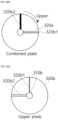
- FIGS. 18 ( a ) and 18 ( b ) show shapes of a loop antenna coil in a state in which two cover parts each having a central hole and a micro-slit overlap each other in different micro-slit directions over an electrode in the form of a loop antenna coil and the cross section of a generated magnetic field;
- FIGS. 19 ( a ), 19 ( b ) and 19 ( c ) show structures in which the number of turns of a coil in the shape of a loop antenna coil electrode is increased to 35 in a state in which the coil electrode is covered with a cover part having a central hole and a micro-slit and the cross section of a magnetic field generated by this structure;
- FIG. 20 shows a graph showing comparisons between the magnitudes of electric field energy according to the number of turns of an antenna coil electrode in a state in which the coil electrode is covered with a cover part having a central hole and a micro-slit.
- the present invention is directed to an energy concentration apparatus, which may be used as a bio-stimulation apparatus that is inserted into the human body and intensively radiates energy such as an electric field or a magnetic field onto a specific part of the human body.
- the present invention is not limited thereto, and may be used in various fields where energy concentration by the present invention can be utilized.
- the present invention is directed to a technology that concentrates generated energy and adjusts the amount and region of energy by forming a micro-slit and a central hole in a cover part provided to cover an electrode with and adjusting one or more factors such as the shape, positions, and number of one or more micro-slits, the size of a central hole, and/or the number of turns of a coil.
- the present invention is directed to an energy concentration apparatus having a central hole and a micro-slit, and may include both a first embodiment provided with a single cover part and a second embodiment provided with a rotatable cover part in a dual structure.
- the present invention is directed to an energy concentration apparatus having a central hole and a micro-slit, the energy concentration apparatus including: a body part 100 ; a loop antenna coil part 200 disposed on the body part 100 ; and a cover part 300 coupled to the body part 100 in order to cover the loop antenna coil part 200 , wherein the cover part 300 may have a central hole 310 and a micro-slit 320 .
- the present invention is directed to an energy concentration apparatus having a central hole and a micro-slit, the energy concentration apparatus including: a body part 100 ; a loop antenna coil part 200 disposed on the body part 100 ; a lower cover part 300 a coupled to the body part 100 in order to cover the loop antenna coil part 200 ; an upper cover part 300 b coupled to the top surface of the lower cover part 300 a in a corresponding shape; a drive unit 400 configured to drive the upper cover part 300 b ; and a control unit 500 configured to control the drive unit.
- the lower cover part 300 a may include a lower central hole 310 a and at least one lower micro-slit 320 a
- the upper cover part 300 b may include an upper central hole 310 b and at least one upper micro-slit 320 b.
- At least one of the lower cover part 300 a and the upper cover part 300 b may be rotatably provided, and an exposed space may be variable as the central holes and the micro-slits overlap each other through rotation.
- the body part 100 is a component configured such that the loop antenna coil part 200 is disposed thereon, and may be provided in a flat plate shape or in a hollow shape in which the inside thereof is concave and empty.
- the cover part 300 is a component coupled to the body part 100 in order to cover the loop antenna coil part 200 disposed on the body part 100 , and has a shape appropriately selected to correspond to the shape of the body part 100 .
- the cover part 300 may be made of an electrically conductive material, and the bottom surface of the body part 100 may be provided with a magnetic material.
- This configuration is intended to allow energy such as a magnetic field to be emitted from the top side of the body part 100 , i.e., from the cover part 300 .
- the reason why a magnetic field is emitted not from the bottom side of the body part 100 but only from the top side of the body part 100 is that there is employed a structure in which a magnetic material is disposed on the bottom surface of the body part 100 to shield a magnetic field when a coil electrode is formed.
- each of the micro-slits 320 , 320 a , and 320 b of the cover parts 300 , 300 a , and 300 b may be formed to continuously connect a corresponding one of the central holes 310 , 310 a , and 310 b and the outer circumference 301 of a corresponding one of the cover parts 300 , 300 a , and 300 b (see FIG. 1 ).
- each of the micro-slits 320 , 320 a , and 320 b may be provided such that the width of the outer end 323 thereof in contact with a corresponding outer circumference 301 is wider than the width of the inner end 322 thereof in contact with a corresponding one of the central holes 310 , 310 a , and 310 b (see FIG. 6 ( a ) ).
- each of the micro-slits 320 , 320 a , and 320 b may be provided such that the width of the outer end 323 thereof in contact with a corresponding outer circumference 301 is narrower than the width of the inner end 322 thereof in contact with a corresponding one of the central holes 310 , 310 a , and 310 b (see FIG. 6 ( b ) ).
- the micro-slit may be provided such that the width of the central portion 321 thereof is wider than the width of the inner and outer ends 322 and 323 thereof (see FIG. 8 ( a ) ).
- the micro-slit may be provided such that the width of the central portion 321 thereof is narrower than the width of the inner and outer ends 322 and 323 thereof (see FIG. 8 ( b ) ).
- energy may be selectively concentrated by adjusting the diameter of the central hole 310 , the width of the micro-slit 320 , and the number of turns of a coil wound in the loop antenna coil part 200 .
- the upper micro-slit 320 b may be provided such that the width thereof is equal to or narrower than the width of the lower micro-slit 320 a . Due to this structure, adjustment may be performed such that when the upper cover part and the lower cover part are rotated and completely overlap each other, the width of the upper micro-slit is equal to or narrower than the width of the lower micro-slit.
- an adjustment may be made to form a space smaller than the width of the lower micro-slit.
- the lower cover part 300 a may include one lower micro-slit 320 a
- the upper cover part 300 b may include a plurality of upper micro-slits 320 b having different widths
- the widths of the upper micro-slits 320 b may be equal to or narrower than the width of the lower micro-slit 320 a (see FIG. 3 ).
- the present embodiment may be provided in a structure in which when at least one of the lower and upper cover parts 300 a and 300 b is rotated, the upper micro-slit 320 b overlaps the lower micro-slit 320 a.
- both the lower and upper cover parts 300 a and 300 b may be rotated, or only one of the lower and upper cover parts 300 a and 300 b may be rotated.
- the reason for this is that since the present embodiment is characterized by overlapping the micro-slits and central holes of the lower and upper cover parts through rotation, overlapping can be achieved even by rotating only one of them.
- the lower and upper cover parts may be driven by the drive unit 400 , and the drive unit 400 may be controlled by the control unit 500 .
- the configurations of the drive unit 400 and the control unit 500 may be implemented in a variety of known methods.
- the control unit 500 may not be disposed inside the energy concentration apparatus, but may be disposed outside the body part and control the drive unit 400 via a wireless connection.
- the upper cover part 300 b includes one rectangular upper micro-slit 320 b (see FIG. 3 ( a ) ), and the lower cover part 300 a includes one rectangular lower micro-slit 320 a larger than the upper micro-slit 320 b (see FIG. 3 ( b ) ).
- the lower micro-slit 320 a is closed by the upper cover part 300 b
- the upper micro-slit 320 b is closed by the lower cover part 300 a
- only the lower central hole 310 a and the upper central hole 310 b overlap each other and are opened (see FIG. 3 ( c ) ).
- the upper cover part 300 b includes two rectangular upper micro-slits 320 b 1 and 320 b 2 having different widths (see FIG. 4 ( a ) ), and the lower cover part 300 a includes one rectangular lower micro-slit 320 a having a width larger than the widths of the upper micro-slits 320 b 1 and 320 b 2 (see FIG. 4 ( b ) ).
- the lower micro-slit 320 a is closed by the upper cover part 300 b
- the upper micro-slits 320 b 1 and 320 b 2 are closed by the lower cover part 300 a
- the upper cover part 300 b is rotated clockwise so that the upper micro-slit 320 b 1 overlaps the lower micro-slit 320 a
- parts of the open space of the lower micro-slit 320 a are closed by the upper cover part 300 b and only the space of the upper micro-slit 320 b 1 is opened (see FIG. 4 ( d ) ).
- the upper micro-slit 320 b 2 may overlap the lower micro-slit 320 a and be opened.
- the upper cover part 300 b includes two rectangular upper micro-slits 320 b 1 and 320 b 2 having different widths (see FIG. 5 ( a ) ), and the lower cover part 300 a includes two rectangular lower micro-slits 320 a 1 and 320 a 2 having widths larger than the widths of the upper micro-slits 320 a 1 and 320 a 2 (see FIG. 5 ( b ) ).
- the upper cover part 300 b includes one tapered cone-shaped upper micro-slit 320 b 1 and one rectangular upper micro-slit slit 320 b 2 (see FIG. 7 ( a ) ), and the lower cover part 300 a includes one rectangular lower micro-slit 320 a having a width wider than the widths of the upper micro-slits 320 b 1 and 320 b 2 (see FIG. 7 ( b ) ).
- the lower micro-slit 320 a is closed by the upper cover part 300 b
- the upper micro-slits 320 b 1 and 320 b 2 are closed by the lower cover part 300 a
- the second embodiment according to the present invention may be provided such that central holes have different shapes and thus a space is variable as the central holes overlap each other through rotation.
- FIGS. 9 and 10 illustrate an embodiment in which central holes have different shapes. For the convenience of description, micro-slits are excluded from the drawings.
- micro-slits having various structures may be combined with such a central hole configuration.
- central holes may have an oval shape or eccentric circle shape, so that when at least one of lower and upper cover parts 300 a and 300 b is rotated, the exposed space of the central hole 310 a is variable as the central holes partially overlap each other (see FIG. 9 ).
- central holes may have an elongated polygonal shape so that when at least one of a lower cover part 300 a and an upper cover part 300 b is rotated, the exposed space of the central hole 310 a is variable as the central holes partially overlap each other (see FIG. 10 ).
- the upper cover part 300 b includes the one oval-shaped upper central hole 310 b (see FIG. 9 ( a ) ), the lower cover part 300 a includes the one oval-shaped lower central hole 310 a having the same size or a different size, and both the central holes are misaligned with each other (see FIG. 9 ( b ) ).
- space “A 1 ” of FIG. 9 ( c ) is opened as the upper central hole 310 b and the lower central hole 310 a overlap each other.
- an open space may be partially increased, as in space “A 2 ” of FIG. 9 ( d ) .
- an open space may be variable so that the open space is further increased as the two central holes 310 a and 310 b almost completely overlap each other, as in space “A 3 ” of FIG. 9 ( e ) .
- An upper cover part 300 b includes one rectangular upper central hole 310 b (see FIG. 10 ( a ) ), a lower cover part 300 a includes one rectangular lower central hole 310 a having the same size or a different size, and both the central holes are misaligned with each other (see FIG. 10 ( b ) ).
- space “B 1 ” of FIG. 10 ( c ) is opened as the upper central hole 310 b and the lower central hole 310 a overlap each other.
- an open space may be partially increased, as in space “B 2 ” of FIG. 10 ( d ) .
- the open space may be variable so that the open space is further increased as the two central holes 310 a and 310 b almost completely overlap each other, as in space “B 3 ” of FIG. 10 ( e ) .
- FIG. 11 shows the shape of a loop antenna coil configured to generate a magnetic field and the cross section of a generated magnetic field.
- FIG. 12 shows a structure in which a central hole is formed over an electrode in the form of a loop antenna coil by covering the electrode with a cover part having only the central hole and the cross section of a generated magnetic field.
- FIG. 12 shows the structure in which the central hole is formed over the electrode in the shape of a loop antenna coil by covering the electrode with the cover part made of an electrically conductive material such as a metal and having the central hole and the cross section of the magnetic field generated by this structure.
- the top of the coil is covered with the cover part made of an electrically conductive material such as metal in order to adjust the distribution of a magnetic field emitted through the coil electrode.
- the magnetic field may not pass through the cover part.
- the cover part made of an electrically conductive material and having a central hole is formed in order to pass a magnetic field through only a desired portion while basically blocking a magnetic field in a region covered with the cover part made of an electrically conductive material.
- the magnetic field distribution it can be seen from the magnetic field distribution that the magnetic field does not pass through not only the region covered with the cover part made of an electrically conductive material but also the portion pierced by the central hole. Therefore, it can be seen that the magnetic field cannot be passed through a portion by simply forming the central hole in the cover part made of an electrically conductive material.
- FIG. 13 shows a structure in which a micro-slit is formed over an electrode in the form of a loop antenna coil by covering the electrode with a cover part having a central hole and the micro-slit and the cross section of a generated magnetic field.
- FIG. 13 shows the structure in which the micro-slit is formed over the electrode in the shape of a loop antenna coil by covering the electrode with the cover part made of an electrically conductive material and having the central hole and the micro-slit and the cross section of the magnetic field generated by this structure.
- the micro-slit is formed in the cover part made of an electrically conductive material.
- a magnetic field passes through the portions in which the central hole and the micro-slit are formed and the passage of a magnetic field is suppressed in a region without a micro-slit. Therefore, unlike in the general magnetic field distribution of the coil electrode shown in FIG. 11 , magnetic field energy can be passed through only a portion, so that the magnetic field distribution may be adjusted.
- the magnitude of the magnetic field in the inner center is increased due to this concentration effect.
- FIG. 14 shows a structure in which the gap between a cover part and a coil electrode is 0.8 mm in a state in which the electrode in the shape of a loop antenna coil is covered with the cover part having a central hole and a micro-slit and the cross section of a generated magnetic field.
- FIG. 14 shows the structure in which the gap between the cover part made of an electrically conductive material and the coil electrode is 0.8 mm in a state in which the electrode in the shape of a loop antenna coil is covered with the cover part made of an electrically conductive material and having the central hole and the micro-slit and the cross section of the generated magnetic field.
- the gap between the cover part made of an electrically conductive material and the coil electrode is 3.8 mm.
- the case of FIG. 14 corresponds to a structure in which the gap between the coil electrode and the cover part made of an electrically conductive material is narrower than the gap in the case of FIG. 13 .
- the magnetic field distribution is similar, but the magnitude of the magnetic field is higher in the center portion thereof.
- FIG. 15 is a graph showing comparisons between the magnitudes of electric field energy according to the gap between a cover part and a coil electrode in a state in which the coil electrode is covered with the cover part having a central hole and a micro-slit.
- FIG. 15 shows the graph showing the comparisons between the magnitudes of electric field energy according to the gap between the cover part made of an electrically conductive material and the coil electrode in a state in which the coil electrode is covered with the cover part made of an electrically conductive material and having the central hole and the micro-slit.
- FIG. 16 shows a structure in which a central hole has a radius of 1 mm in a state in which an electrode in the shape of a loop antenna coil is covered with a cover part having the central hole and a micro-slit and the cross section of a generated magnetic field.
- FIG. 16 shows the structure in which the central hole has a radius of 1 mm in a state in which the electrode in the shape of a loop antenna coil is covered with the cover part having the central hole and the micro-slit and the cross section of the generated magnetic field.
- FIG. 17 shows a graph showing comparisons between the magnitudes of electric field energy according to the size of a central hole in a state in which a coil electrode is covered with a cover part having the central hole and a micro-slit.
- FIG. 17 shows the graph showing the comparisons according to the size of the central hole.
- the central hole has a radius of 5 mm.
- the case of FIG. 16 corresponds to a structure in which the size of the central hole is smaller. It can be seen that as the size of the central hole is decreased, magnetic field energy is concentrated, and thus the magnitude of a magnetic field is increased. Accordingly, it can be seen that the magnitude and area of concentrated magnetic field energy may be adjusted by adjusting the size of the central hole of the cover part made of an electrically conductive material and having a micro-slit.
- FIG. 18 shows the shape of a loop antenna coil in a state in which two cover parts each having a central hole and a micro-slit overlap each other in different micro-slit directions over an electrode in the form of a loop antenna coil and the cross section of a generated magnetic field.
- FIG. 18 shows the shape of the loop antenna coil in a state in which the two cover parts made of an electrically conductive material and each having a central hole and a micro-slit overlap each other in the different micro-slit directions over the electrode in the form of a loop antenna coil and the cross section of the generated magnetic field. It can be seen from the magnetic field distribution that a magnetic field appears high in the region of the central hole and the magnetic field passes through the region of the micro-slit. As a method of allowing the magnetic field to pass through the region of the central hole and suppressing the passage of the magnetic field in the region of the micro-slit, the two cover parts made of an electrically conductive material are provided to overlap each other, but the directions in which micro-slits are formed are different.
- the magnetic field passes through only the region of the central hole and the magnetic field does not pass through the other parts. Therefore, by using this method, energy may be concentrated by passing the magnetic field through only a desired region, and the area onto which magnetic field energy is radiated may be accurately adjusted.
- FIG. 19 shows a structure in which the number of turns of a coil in the shape of a loop antenna coil electrode is increased to 35 in a state in which the coil electrode is covered with a cover part having a central hole and a micro-slit and the cross section of a magnetic field generated by this structure.
- FIG. 20 shows a graph showing comparisons between the magnitudes of electric field energy according to the number of turns of an antenna coil electrode in a state in which the coil electrode is covered with a cover part having a central hole and a micro-slit.
- FIG. 20 shows the graph showing the comparisons according to the number of turns of the coil.
- the number of turns of the coil is 11.
- the case of FIG. 19 corresponds a structure in which the number of turns of the coil electrode is larger. It can be seen from the results that as the number of turns of the coil electrode is increased, magnetic field energy is concentrated, and thus the magnitude of the magnetic field increases. Therefore, it can be seen that the magnitude and region of concentrated magnetic field energy may be adjusted by adjusting the number of turns of the coil electrode.
- a first advantage of the present invention is to obtain high energy by concentrating the energy formed on an electrode.
- a second advantage of the present invention is to adjust the area to which energy is applied as desired by allowing energy to be radiated only onto a specific area of interest.
- a third advantage of the present invention is to adjust the magnitude and region of concentrated energy by additionally forming a micro-slit structure over an electrode.
- a fourth advantage of the present invention is to variably adjust the space to which energy is applied by using the micro-slits in a dual structure.
- a fifth advantage of the present invention is to concentrate energy only by using a simple method of forming the micro-slit structure over the electrode without the construction of a complicated system in which a plurality of array electrodes is formed to concentrate energy.
- a sixth advantage of the present invention is to adjust the amount and area of energy by adjusting a factor such as the shapes and positions of the micro-slits, the number of micro-slits, the diameter of the central holes, and/or the number of turns of the coil.
Landscapes
- Health & Medical Sciences (AREA)
- Engineering & Computer Science (AREA)
- Life Sciences & Earth Sciences (AREA)
- Biomedical Technology (AREA)
- General Health & Medical Sciences (AREA)
- Nuclear Medicine, Radiotherapy & Molecular Imaging (AREA)
- Radiology & Medical Imaging (AREA)
- Animal Behavior & Ethology (AREA)
- Public Health (AREA)
- Veterinary Medicine (AREA)
- Chemical & Material Sciences (AREA)
- Organic Chemistry (AREA)
- Genetics & Genomics (AREA)
- Bioinformatics & Cheminformatics (AREA)
- Biotechnology (AREA)
- Wood Science & Technology (AREA)
- Zoology (AREA)
- Neurology (AREA)
- General Engineering & Computer Science (AREA)
- Biochemistry (AREA)
- Cell Biology (AREA)
- Sustainable Development (AREA)
- Hospice & Palliative Care (AREA)
- Medicinal Chemistry (AREA)
- Pain & Pain Management (AREA)
- Microbiology (AREA)
- Details Of Aerials (AREA)
- Magnetic Treatment Devices (AREA)
Abstract
Description
Claims (20)
Applications Claiming Priority (2)
| Application Number | Priority Date | Filing Date | Title |
|---|---|---|---|
| KR10-2020-0083376 | 2020-07-07 | ||
| KR1020200083376A KR102491003B1 (en) | 2020-07-07 | 2020-07-07 | Energy Concentration Apparatus having center hole and micro slit |
Publications (2)
| Publication Number | Publication Date |
|---|---|
| US20220008740A1 US20220008740A1 (en) | 2022-01-13 |
| US12186576B2 true US12186576B2 (en) | 2025-01-07 |
Family
ID=79172006
Family Applications (1)
| Application Number | Title | Priority Date | Filing Date |
|---|---|---|---|
| US17/337,718 Active 2043-10-10 US12186576B2 (en) | 2020-07-07 | 2021-06-03 | Energy concentration apparatus having central hole and micro-slit |
Country Status (2)
| Country | Link |
|---|---|
| US (1) | US12186576B2 (en) |
| KR (1) | KR102491003B1 (en) |
Citations (4)
| Publication number | Priority date | Publication date | Assignee | Title |
|---|---|---|---|---|
| JPS6384103A (en) | 1986-09-29 | 1988-04-14 | Kanazawa Univ | Eddy current type strong ac magnetic field generator |
| US20020111614A1 (en) * | 2001-02-13 | 2002-08-15 | Werny Scott H. | Dynamic magnetic device and method, and components thereof |
| KR20180051314A (en) | 2016-11-08 | 2018-05-16 | 오세경 | Torsion wave generator beneficial to the human body |
| KR20200038844A (en) | 2018-10-04 | 2020-04-14 | 한국과학기술연구원 | System for monitoring post-translational modification of protein using bio-sensor with gap and manufactureing method for bio-sensor |
Family Cites Families (2)
| Publication number | Priority date | Publication date | Assignee | Title |
|---|---|---|---|---|
| KR20070117030A (en) * | 2006-06-07 | 2007-12-12 | 엘지전자 주식회사 | Miniature Shutter Device |
| JP2012000341A (en) | 2010-06-18 | 2012-01-05 | Nishi Nippon Electric Wire & Cable Co Ltd | Magnetic stimulation coil |
-
2020
- 2020-07-07 KR KR1020200083376A patent/KR102491003B1/en active Active
-
2021
- 2021-06-03 US US17/337,718 patent/US12186576B2/en active Active
Patent Citations (4)
| Publication number | Priority date | Publication date | Assignee | Title |
|---|---|---|---|---|
| JPS6384103A (en) | 1986-09-29 | 1988-04-14 | Kanazawa Univ | Eddy current type strong ac magnetic field generator |
| US20020111614A1 (en) * | 2001-02-13 | 2002-08-15 | Werny Scott H. | Dynamic magnetic device and method, and components thereof |
| KR20180051314A (en) | 2016-11-08 | 2018-05-16 | 오세경 | Torsion wave generator beneficial to the human body |
| KR20200038844A (en) | 2018-10-04 | 2020-04-14 | 한국과학기술연구원 | System for monitoring post-translational modification of protein using bio-sensor with gap and manufactureing method for bio-sensor |
Also Published As
| Publication number | Publication date |
|---|---|
| KR20220005788A (en) | 2022-01-14 |
| KR102491003B1 (en) | 2023-01-19 |
| US20220008740A1 (en) | 2022-01-13 |
Similar Documents
| Publication | Publication Date | Title |
|---|---|---|
| US11260246B2 (en) | Apparatus and methods for magnetic control of radiation electron beam | |
| US12564727B2 (en) | System and method for multi-coil steerable and selectively focussed transcranial magnetic stimulation | |
| CN114668986B (en) | A radiotherapy device, a photon flash therapy system, and an ultra-high energy electron flash therapy system | |
| CN108023263A (en) | A kind of magnetic field and the terahertz pulse generator of regulating and controlling voltage | |
| Nakano et al. | Unbalanced-mode spiral antenna backed by an extremely shallow cavity | |
| JP2025500638A5 (en) | ||
| US11911098B2 (en) | Apparatus for treating tumors by evanescent waves | |
| JP2010029594A (en) | Corpuscular beam irradiating apparatus and treatment planning device | |
| US12186576B2 (en) | Energy concentration apparatus having central hole and micro-slit | |
| US12109030B2 (en) | Bio sensor having piller-typed electrode structure coated non-conductive material | |
| US7919759B2 (en) | Charged particle beam irradiator and rotary gantry | |
| US5680432A (en) | Method and apparatus for generating a circulating x-ray for fast computed tomography | |
| KR20150088447A (en) | Solid state plasma antenna | |
| US20060202644A1 (en) | Linear accelerator | |
| US20120012575A1 (en) | Radio Frequency Heating Fork | |
| CN107317093A (en) | Single helical antenna for improving low elevation characteristic | |
| KR101302814B1 (en) | Electromedical device for the non-invasive reduction or removal of subcutaneous adipose tissue | |
| JP2025527432A (en) | Bent Magnet | |
| CN118105631A (en) | An electromagnetic focusing device | |
| Hirose et al. | Fundamental study on novel loop-line antennas radiating a circularly polarized wave | |
| US10674592B2 (en) | Plasma generation apparatus | |
| KR102323438B1 (en) | Electric field shaping apparatus and target processing device using electric field | |
| KR20200060887A (en) | Magnetic stimulation apparatus and method with focused target region | |
| WO2026083144A1 (en) | Scanning electromagnet | |
| JPH0717315Y2 (en) | Simple local induction heating type applicator device |
Legal Events
| Date | Code | Title | Description |
|---|---|---|---|
| AS | Assignment |
Owner name: UIF (UNIVERSITY INDUSTRY FOUNDATION), YONSEI UNIVERSITY, KOREA, REPUBLIC OF Free format text: ASSIGNMENT OF ASSIGNORS INTEREST;ASSIGNORS:CHOI, HEON JIN;SUNG, JAE SUK;REEL/FRAME:057246/0954 Effective date: 20210525 |
|
| FEPP | Fee payment procedure |
Free format text: ENTITY STATUS SET TO UNDISCOUNTED (ORIGINAL EVENT CODE: BIG.); ENTITY STATUS OF PATENT OWNER: SMALL ENTITY |
|
| FEPP | Fee payment procedure |
Free format text: ENTITY STATUS SET TO SMALL (ORIGINAL EVENT CODE: SMAL); ENTITY STATUS OF PATENT OWNER: SMALL ENTITY |
|
| STPP | Information on status: patent application and granting procedure in general |
Free format text: DOCKETED NEW CASE - READY FOR EXAMINATION |
|
| STPP | Information on status: patent application and granting procedure in general |
Free format text: NON FINAL ACTION MAILED |
|
| STPP | Information on status: patent application and granting procedure in general |
Free format text: RESPONSE TO NON-FINAL OFFICE ACTION ENTERED AND FORWARDED TO EXAMINER |
|
| STPP | Information on status: patent application and granting procedure in general |
Free format text: NOTICE OF ALLOWANCE MAILED -- APPLICATION RECEIVED IN OFFICE OF PUBLICATIONS |
|
| STPP | Information on status: patent application and granting procedure in general |
Free format text: NOTICE OF ALLOWANCE MAILED -- APPLICATION RECEIVED IN OFFICE OF PUBLICATIONS |
|
| STPP | Information on status: patent application and granting procedure in general |
Free format text: PUBLICATIONS -- ISSUE FEE PAYMENT VERIFIED |
|
| STCF | Information on status: patent grant |
Free format text: PATENTED CASE |