US12184007B2 - Electric plug connector - Google Patents
Electric plug connector Download PDFInfo
- Publication number
- US12184007B2 US12184007B2 US17/763,115 US202017763115A US12184007B2 US 12184007 B2 US12184007 B2 US 12184007B2 US 202017763115 A US202017763115 A US 202017763115A US 12184007 B2 US12184007 B2 US 12184007B2
- Authority
- US
- United States
- Prior art keywords
- housing
- plug connector
- contact carrier
- housing part
- insertion opening
- Prior art date
- Legal status (The legal status is an assumption and is not a legal conclusion. Google has not performed a legal analysis and makes no representation as to the accuracy of the status listed.)
- Active, expires
Links
Images


Classifications
-
- H—ELECTRICITY
- H01—ELECTRIC ELEMENTS
- H01R—ELECTRICALLY-CONDUCTIVE CONNECTIONS; STRUCTURAL ASSOCIATIONS OF A PLURALITY OF MUTUALLY-INSULATED ELECTRICAL CONNECTING ELEMENTS; COUPLING DEVICES; CURRENT COLLECTORS
- H01R13/00—Details of coupling devices of the kinds covered by groups H01R12/70 or H01R24/00 - H01R33/00
- H01R13/46—Bases; Cases
- H01R13/502—Bases; Cases composed of different pieces
-
- H—ELECTRICITY
- H01—ELECTRIC ELEMENTS
- H01R—ELECTRICALLY-CONDUCTIVE CONNECTIONS; STRUCTURAL ASSOCIATIONS OF A PLURALITY OF MUTUALLY-INSULATED ELECTRICAL CONNECTING ELEMENTS; COUPLING DEVICES; CURRENT COLLECTORS
- H01R13/00—Details of coupling devices of the kinds covered by groups H01R12/70 or H01R24/00 - H01R33/00
- H01R13/02—Contact members
- H01R13/10—Sockets for co-operation with pins or blades
-
- H—ELECTRICITY
- H01—ELECTRIC ELEMENTS
- H01R—ELECTRICALLY-CONDUCTIVE CONNECTIONS; STRUCTURAL ASSOCIATIONS OF A PLURALITY OF MUTUALLY-INSULATED ELECTRICAL CONNECTING ELEMENTS; COUPLING DEVICES; CURRENT COLLECTORS
- H01R13/00—Details of coupling devices of the kinds covered by groups H01R12/70 or H01R24/00 - H01R33/00
- H01R13/40—Securing contact members in or to a base or case; Insulating of contact members
-
- H—ELECTRICITY
- H01—ELECTRIC ELEMENTS
- H01R—ELECTRICALLY-CONDUCTIVE CONNECTIONS; STRUCTURAL ASSOCIATIONS OF A PLURALITY OF MUTUALLY-INSULATED ELECTRICAL CONNECTING ELEMENTS; COUPLING DEVICES; CURRENT COLLECTORS
- H01R13/00—Details of coupling devices of the kinds covered by groups H01R12/70 or H01R24/00 - H01R33/00
- H01R13/46—Bases; Cases
- H01R13/502—Bases; Cases composed of different pieces
- H01R13/506—Bases; Cases composed of different pieces assembled by snap action of the parts
-
- H—ELECTRICITY
- H01—ELECTRIC ELEMENTS
- H01R—ELECTRICALLY-CONDUCTIVE CONNECTIONS; STRUCTURAL ASSOCIATIONS OF A PLURALITY OF MUTUALLY-INSULATED ELECTRICAL CONNECTING ELEMENTS; COUPLING DEVICES; CURRENT COLLECTORS
- H01R13/00—Details of coupling devices of the kinds covered by groups H01R12/70 or H01R24/00 - H01R33/00
- H01R13/46—Bases; Cases
- H01R13/516—Means for holding or embracing insulating body, e.g. casing, hoods
-
- H—ELECTRICITY
- H01—ELECTRIC ELEMENTS
- H01R—ELECTRICALLY-CONDUCTIVE CONNECTIONS; STRUCTURAL ASSOCIATIONS OF A PLURALITY OF MUTUALLY-INSULATED ELECTRICAL CONNECTING ELEMENTS; COUPLING DEVICES; CURRENT COLLECTORS
- H01R13/00—Details of coupling devices of the kinds covered by groups H01R12/70 or H01R24/00 - H01R33/00
- H01R13/62—Means for facilitating engagement or disengagement of coupling parts or for holding them in engagement
- H01R13/627—Snap or like fastening
- H01R13/6271—Latching means integral with the housing
-
- H—ELECTRICITY
- H01—ELECTRIC ELEMENTS
- H01R—ELECTRICALLY-CONDUCTIVE CONNECTIONS; STRUCTURAL ASSOCIATIONS OF A PLURALITY OF MUTUALLY-INSULATED ELECTRICAL CONNECTING ELEMENTS; COUPLING DEVICES; CURRENT COLLECTORS
- H01R13/00—Details of coupling devices of the kinds covered by groups H01R12/70 or H01R24/00 - H01R33/00
- H01R13/73—Means for mounting coupling parts to apparatus or structures, e.g. to a wall
- H01R13/74—Means for mounting coupling parts in openings of a panel
-
- H—ELECTRICITY
- H01—ELECTRIC ELEMENTS
- H01R—ELECTRICALLY-CONDUCTIVE CONNECTIONS; STRUCTURAL ASSOCIATIONS OF A PLURALITY OF MUTUALLY-INSULATED ELECTRICAL CONNECTING ELEMENTS; COUPLING DEVICES; CURRENT COLLECTORS
- H01R13/00—Details of coupling devices of the kinds covered by groups H01R12/70 or H01R24/00 - H01R33/00
- H01R13/46—Bases; Cases
- H01R13/52—Dustproof, splashproof, drip-proof, waterproof, or flameproof cases
- H01R13/5219—Sealing means between coupling parts, e.g. interfacial seal
-
- H—ELECTRICITY
- H01—ELECTRIC ELEMENTS
- H01R—ELECTRICALLY-CONDUCTIVE CONNECTIONS; STRUCTURAL ASSOCIATIONS OF A PLURALITY OF MUTUALLY-INSULATED ELECTRICAL CONNECTING ELEMENTS; COUPLING DEVICES; CURRENT COLLECTORS
- H01R13/00—Details of coupling devices of the kinds covered by groups H01R12/70 or H01R24/00 - H01R33/00
- H01R13/73—Means for mounting coupling parts to apparatus or structures, e.g. to a wall
- H01R13/74—Means for mounting coupling parts in openings of a panel
- H01R13/748—Means for mounting coupling parts in openings of a panel using one or more screws
Definitions
- the disclosure relates to an electrical plug connector.
- Electrical plug connectors whether they are built-in plug connector, also referred to as chassis sockets, or cable plug connectors, typically consist of a housing with at least one insertion opening for a complementary plug connector, and a contact carrier, arranged in said housing, for the electrical contacts accessible through the insertion opening(s).
- housings and contact carriers The mechanical as well as electrical requirements are very different for housings and contact carriers, which has resulted in that there are countless combinations of housing variants and variants of contact carriers, which only match in very specific combinations. Even for plug connectors of the same standard but with a different number of contacts or a different contact arrangement, in most cases, completely different housings must be used, which causes a high expense in production and storage of the components.
- EP 3382818 A1 discloses a sealed feed-through of a standard interface through a wall, wherein the sealing housing consisting of multiple parts, surrounding this standard interface functional on its own is arranged on both sides of the wall. In one of the parts of the sealing housing, an annular, flat groove open towards the wall is formed for accommodating a washer.
- An electrical plug with a coding function is the subject matter of EP 3252876 A1.
- the stationary part of the plug connection has a housing with a (square) annular insertion opening for the coding element of the mating plug, which could be interpreted as an annular extension of the mating plug.
- the electrical contacts are held in a structure, the design of which is not disclosed or comprehensible. According to an interpretation of the drawings, it is a single-piece section of the housing of the plug.
- EP 2431777 A1 describes a plug arrangement, in which, in the housing of a built-in plug socket, an annular insertion opening is designed for a plug-in extension of a mating plug.
- the contact is held in the central part of the housing, which functions as a contact carrier.
- CN 204615057 U discloses a plug connector, in which a contact carrier is inserted into a housing as a separate component, wherein on the insertion side, between the inner wall of the housing and the outer surface of the contact carrier, an annular intermediate space is formed as an intermediate space for the annular extension of a mating plug connector.
- the contact carrier contains the electrical contacts and is fixed by a rear cover in the housing having only one wall, which contact carrier can be connected to the housing by means of a latching connection.
- a projecting mounting flange is arranged on the housing.
- An object of the present disclosure was to overcome the shortcomings of the prior art and to provide a device, by means of which the structure of an electrical plug connector can be simplified, and each component can be optimally constructed according to its requirements.
- An object of the present disclosure was to overcome the shortcomings of the prior art and to provide a device representing an optimally sealed plug connector with easy handling and a simple and quick mounting with only few components.
- the device according to the disclosure is fundamentally characterized by a receiving opening for the contact carrier formed inside the internal housing part at the level of overlap of the concentric housing parts, which receiving opening is formed by the cylindrical volume inside the internal housing part, and in that the contact carrier extends into the longitudinal section of the inner housing part abutting on its inner side, which overlaps with the outer housing part.
- the housing which is mostly responsible for the mechanical stability, which is also particularly significant for establishing and releasing the plug connection in a simple manner, can be designed optimally for this purpose.
- the contact carrier may be geared completely to the electrical requirements and achieve the fixing of the electrical contacts and their electrically insulating arrangement in the housing alone.
- the design of the housing is independent of the electrical requirements of the contact carrier, it can always have the same design, particularly with regard to the dimensions inside the inner housing part of the housing and can thus be provided as a standard component suitable for many types of plugs.
- Guide structures may be formed between the inner wall of the inner housing part and the contact carrier. This facilitates the assembly of the housing and the contact carrier and ensures the correct positioning of the contact carrier in the housing.
- An advantageous embodiment of the disclosure provides that a connecting mechanism between the contact carrier and the housing is provided, in order to securely maintain the positioning of the connecting mechanism during plugging-in and unplugging operations.
- the connecting mechanism may be constructed as a latching and/or snap connection.
- the positioning of the contact carrier in the housing being the same for all identically designed plug connectors is ensured according to a further optional feature of the disclosure in that advantageously, at least one stop for the contact carrier is provided.
- a preferred embodiment of a plug connector according to the disclosure provides its construction as a built-in plug connector or chassis socket and is characterized by a mounting flange radially projecting from the outer housing part, which mounting flange is preferably positioned on the insertion-side end of the outer housing part.
- a seal is present in this design, which covers a front side of the mounting flange and has at least one through hole corresponding to the insertion opening.
- a front plate which covers the front side of the mounting flange and possibly also the seal towards the front serves the protection of the underlying components and the stability of the entire arrangement.
- the plug connector is characterized by a locking mechanism for an inserted complementary plug connector, comprising at least one locking element, which is arranged on the contact carrier.
- an unlocking element may also be present in this embodiment, which protrudes from the locking element through recesses in the housing and possibly the front plate on the front side of the housing and/or the front plate.
- an integrally formed dome is advantageously arranged on the seal in the embodiments with a seal and a front plate for maintaining the sealing effect well, which dome serves to accommodate the unlocking element and protrudes forwards.
- the dome protrudes through the front plate on its front side.
- An advantageous embodiment provides a plug connector with a contact carrier designed for XLR contacts.
- a different advantageous embodiment provides a plug connector with a contact carrier designed for the contacts for data plugs, in particular RJ45 plugs.
- FIG. 1 an exploded view of a first embodiment of a built-in plug connector according to the disclosure
- FIG. 2 a front view of the housing of the built-in plug of FIG. 1 ;
- FIG. 3 a rear view of the housing of the built-in plug connector of FIG. 1 ;
- FIG. 4 a longitudinal section through the housing of the built-in plug connector of FIG. 1 in the vertical central plane
- FIG. 5 a longitudinal section according to FIG. 4 through a built-in plug connector of FIG. 1 ;
- FIG. 6 a perspective view of a further embodiment of a built-in plug connector according to the disclosure.
- FIG. 7 a perspective rear view of the built-in plug connector of FIG. 6 ;
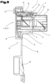
- FIG. 8 an exploded view of the built-in plug connector of FIG. 6 ;
- FIG. 9 a longitudinal section through the built-in plug connector of FIG. 6 in the vertical central plane.
- FIGS. 1 to 5 show a first advantageous embodiment of the built-in plug connector according to the disclosure, in a variant of the XLR standard with three contacts, as a female part of the plug connection and/or as a built-in socket.
- the built-in socket of FIGS. 1 to 5 as an example for an electrical plug connector according to the disclosure has a housing 1 with at least one insertion opening 2 for a complementary plug connector.
- a contact carrier 3 for the electrical contacts accessible through its contact insertion opening(s) 4 is present.
- the contact carrier 3 is designed for plug connections according to the XLR standard, in this example shown having three contacts.
- the housing 1 is made up of two concentrically arranged housing parts, an outer housing part 5 and an inner housing part 6 , which are spaced from one another by an annular gap 7 , wherein said annular gap 7 forms an annular insertion opening for a plug projection, in the form of a socket, of a complementary cable connector.
- An annular bottom 8 connects the two housing parts 5 , 6 at the end of the housing 1 located opposite the insertion opening 2 .
- the cylindrical volume inside the internal housing part 6 forms the receiving space 9 for the contact carrier 3 .
- a mounting flange 10 shown having a square outline is shown by way of example on the front end of the housing 1 , which mounting flange 10 projects radially from the housing 1 , in particular from the outer housing part 5 , and in which also mounting bores 11 may be recessed. Other contours may also occur, for example circular or rectangular contours. Only one or multiple small mounting lugs may also possibly be arranged on an otherwise sole cylindrical housing 1 .
- flexible strips 17 start from the plate-shaped part 14 , at the ends of which strips 17 for example pot-shaped sealing plug 18 is provided, for insertion into the through hole 16 and preferably also the annular gap 7 between the inner housing part 6 and outer housing part 5 , in order to be able to tightly close the built-in plug connector when the complementary plate-shaped part is not plugged in.
- a front plate 19 is present, which covers the front side of the mounting flange 10 and possibly also the seal 13 , in particular its plate-shaped section 14 , towards the front.
- This front plate 19 has its own mounting bores 20 at the locations of the mounting bores 11 of the mounting flange 10 , possibly also the through holes 15 of the seal 13 .
- a cutout hole as an insertion opening 21 is also present.
- the plug connector according to the disclosure also has a locking mechanism 22 for an inserted complementary plug connector, in order to prevent inadvertent unplugging of the cable plug connector and thus a release of the plug connection.
- This mechanism 22 comprises at least one locking element 23 , which may be arranged on the contact carrier 3 .
- an unlocking element 24 in operative connection to the locking element 23 is integrated into the locking mechanism 22 .
- the unlocking element 24 protrudes, starting from the locking element 23 , through recesses and/or protuberances 25 in the housing 1 and a radial recess 26 in the central cutout 21 of the front plate 19 on the front side of the housing 1 and/or the front plate 19 , from where it is accessible for the user to actuate.
- the section of the unlocking element 24 protruding through the front plate 19 is covered by a dome 27 integrally formed onto the seal 13 , in particular to the plate-shaped section 14 , for accommodating the unlocking element 24 , which dome 27 protrudes forward and preferably protrudes through the front plate 19 beyond its front side.
- the contact carrier 3 is preferably designed as an insertion part, and guide structures are possibly formed between the inner wall of the inner housing part 6 and the contact carrier 3 .
- a connecting mechanism may be in effect between the contact carrier 3 and the housing 1 , in order to securely hold the contact carrier 3 in the housing 1 . This may take place, if need be, by means of crimping the rear edge of the housing 1 radially inwards over an outer circumferential edge of the inserted contact carrier 3 .
- Another alternative consists in that the connecting mechanism is designed as a latching and/or snap connection.
- the contact carrier 3 has a shoulder 31 , which extends over a large part of the circumference and is formed by an increase in diameter between the insertion-side longitudinal section and the section connecting thereto.
- a shoulder 32 is formed on the inner side of the housing 1 , approximately at the level of the base 8 , which connects the inner housing part 6 to the outer housing part 5 .
- the shoulder 31 of the contact carrier 3 comes to a stop upon insertion into the housing 1 , whereby the desired positioning of the two components relative to one another is ensured.
- the recess 34 on the front side, existing in particularly XLR contact carriers 3 , to which the region of the bearing for the locking mechanism 22 connects, is covered by a catch 28 protruding towards the center of the insertion opening 2 .
- This catch 28 may advantageously have two guides 29 extending in parallel with the longitudinal axis of the housing 1 , between which guides 29 particularly the spring of the locking mechanism 22 is guided and held.
- FIGS. 6 to 9 show a further and possibly independent embodiment of a built-in plug connector according to the disclosure, wherein again, equal reference numbers and/or component designations are used for equal parts as in FIGS. 1 to 5 above. In order to avoid unnecessary repetitions, it is pointed to/reference is made to the detailed description of the preceding figures.
- FIGS. 6 to 9 show a built-in socket for a data plug, in particular a RJ-45 plug.
- the contact carrier 3 of this version of the built-in plug socket according to the disclosure is covered and protected on the rear side of the housing 1 by a contact feed-through 29 and a rear covering 30 .
Landscapes
- Connector Housings Or Holding Contact Members (AREA)
- Coupling Device And Connection With Printed Circuit (AREA)
Abstract
Description
| List of |
| 1 | Housing | 36 |
| 2 | Insertion opening | 37 |
| 3 | Contact carrier | 38 |
| 4 | Insertion openings | 39 |
| 5 | Outer housing part | 40 |
| 6 | Inner housing part | 41 |
| 7 | Annular gap | 42 |
| 8 | Base | 43 |
| 9 | Receiving space | 44 |
| 10 | Mounting flange | 45 |
| 11 | Mounting bores | 46 |
| 12 | 47 | |
| 13 | Seal | 48 |
| 14 | Plate-shaped section | 49 |
| 15 | Through hole | 50 |
| 16 | Central cutout | 51 |
| 17 | Strip | 52 |
| 18 | Sealing plug | 53 |
| 19 | Front plate | 54 |
| 20 | Mounting bore | 55 |
| 21 | Central cutout | 56 |
| 22 | Locking mechanism | 57 |
| 23 | Locking elements | 58 |
| 24 | Unlocking element | 59 |
| 25 | Protuberance/Recess | 60 |
| 26 | Radial recess | 61 |
| 27 | Dome | 62 |
| 28 | Catch | 63 |
| 29 | Contact feed-through | 64 |
| 30 | Covering | 65 |
| 31 | |
|
| 32 | |
|
| 33 | |
|
| 34 | Recess | |
| 35 | ||
Claims (18)
Applications Claiming Priority (3)
| Application Number | Priority Date | Filing Date | Title |
|---|---|---|---|
| ATA50815/2019 | 2019-09-24 | ||
| ATA50815/2019A AT523021B1 (en) | 2019-09-24 | 2019-09-24 | Electrical connector |
| PCT/EP2020/025424 WO2021058127A1 (en) | 2019-09-24 | 2020-09-21 | Electric plug connector |
Publications (2)
| Publication Number | Publication Date |
|---|---|
| US20220344865A1 US20220344865A1 (en) | 2022-10-27 |
| US12184007B2 true US12184007B2 (en) | 2024-12-31 |
Family
ID=72615813
Family Applications (1)
| Application Number | Title | Priority Date | Filing Date |
|---|---|---|---|
| US17/763,115 Active 2041-08-24 US12184007B2 (en) | 2019-09-24 | 2020-09-21 | Electric plug connector |
Country Status (11)
| Country | Link |
|---|---|
| US (1) | US12184007B2 (en) |
| EP (1) | EP4035229B1 (en) |
| JP (1) | JP7389897B2 (en) |
| KR (1) | KR20220057581A (en) |
| CN (2) | CN119994537A (en) |
| AT (1) | AT523021B1 (en) |
| AU (1) | AU2020356148A1 (en) |
| BR (1) | BR112022004625A2 (en) |
| CA (1) | CA3153981A1 (en) |
| MX (1) | MX2022003126A (en) |
| WO (1) | WO2021058127A1 (en) |
Cited By (1)
| Publication number | Priority date | Publication date | Assignee | Title |
|---|---|---|---|---|
| US20240128699A1 (en) * | 2022-10-18 | 2024-04-18 | Jess-Link Products Co., Ltd. | Power storage connector |
Families Citing this family (1)
| Publication number | Priority date | Publication date | Assignee | Title |
|---|---|---|---|---|
| US12278446B2 (en) | 2021-08-18 | 2025-04-15 | R.A. Phillips Industries, Inc. | Self-sealing electrical plug-and-socket assembly |
Citations (17)
| Publication number | Priority date | Publication date | Assignee | Title |
|---|---|---|---|---|
| US6241554B1 (en) * | 1999-06-03 | 2001-06-05 | Yazaki Corporation | Waterproof connector and method of assembling the same |
| US6257928B1 (en) * | 1999-08-03 | 2001-07-10 | Yazaki Corporation | Waterproof connector and method of assembling the same |
| US7507125B2 (en) * | 2007-02-02 | 2009-03-24 | Japan Aviation Electronics Industry Limited | Connector and device equipped with the same |
| US20090305542A1 (en) * | 2008-06-04 | 2009-12-10 | Hirose Electric Co., Ltd. | Waterproof connector and waterproof apparatus using the same |
| CN201498774U (en) | 2009-07-23 | 2010-06-02 | 宁波日鼎电子科技有限公司 | Connector of current difference conductor needle |
| EP2431777A1 (en) | 2010-09-21 | 2012-03-21 | Fujitsu Limited | Connection device |
| CN204516967U (en) | 2015-04-17 | 2015-07-29 | 宁波海曙区西尚电子有限公司 | The two female seat network connector receptacles of through type |
| CN204615057U (en) | 2015-04-17 | 2015-09-02 | 宁波海曙区西尚电子有限公司 | Waterproof combo socket |
| US9837755B2 (en) * | 2016-03-31 | 2017-12-05 | Advanced-Connectek Inc. | Waterproof bushing connector assembly, waterproof bushing receptacle connector and waterproof bushing plug connector |
| EP3252876A1 (en) | 2016-06-01 | 2017-12-06 | Delphi Technologies, Inc. | Electrical connector with encoding function |
| CN207009841U (en) | 2017-06-12 | 2018-02-13 | 西安丰石电子科技有限公司 | A pin type radio frequency coaxial connector |
| JP2018152215A (en) | 2017-03-13 | 2018-09-27 | 株式会社オートネットワーク技術研究所 | Terminal unit and connector |
| CN109273904A (en) | 2018-10-17 | 2019-01-25 | 德尔特微波电子(南京)有限公司 | A kind of screw-on radio frequency (RF) coaxial connector |
| WO2019139797A1 (en) | 2018-01-12 | 2019-07-18 | Commscope Technologies Llc | Blind-mate pim testing adapter connector and fixture |
| US10396490B2 (en) * | 2017-03-16 | 2019-08-27 | Molex, Llc | Connector assembly and connector cover |
| EP3382818B1 (en) | 2017-03-31 | 2020-05-13 | Yamaichi Electronics Deutschland GmbH | Sealing device, method and use |
| EP3748784A1 (en) | 2019-06-05 | 2020-12-09 | Delta Plus Co., Ltd. | Electrical connector |
Family Cites Families (2)
| Publication number | Priority date | Publication date | Assignee | Title |
|---|---|---|---|---|
| JP5981294B2 (en) * | 2012-10-12 | 2016-08-31 | 矢崎総業株式会社 | Charging inlet device |
| AT522949B1 (en) * | 2019-09-24 | 2021-05-15 | Neutrik Ag | poetry |
-
2019
- 2019-09-24 AT ATA50815/2019A patent/AT523021B1/en not_active IP Right Cessation
-
2020
- 2020-09-21 MX MX2022003126A patent/MX2022003126A/en unknown
- 2020-09-21 JP JP2022518992A patent/JP7389897B2/en active Active
- 2020-09-21 WO PCT/EP2020/025424 patent/WO2021058127A1/en not_active Ceased
- 2020-09-21 CA CA3153981A patent/CA3153981A1/en not_active Abandoned
- 2020-09-21 AU AU2020356148A patent/AU2020356148A1/en not_active Abandoned
- 2020-09-21 KR KR1020227011076A patent/KR20220057581A/en not_active Ceased
- 2020-09-21 EP EP20776070.3A patent/EP4035229B1/en active Active
- 2020-09-21 BR BR112022004625A patent/BR112022004625A2/en not_active Application Discontinuation
- 2020-09-21 CN CN202510209146.5A patent/CN119994537A/en active Pending
- 2020-09-21 US US17/763,115 patent/US12184007B2/en active Active
- 2020-09-21 CN CN202080067438.5A patent/CN114450857A/en active Pending
Patent Citations (21)
| Publication number | Priority date | Publication date | Assignee | Title |
|---|---|---|---|---|
| US6241554B1 (en) * | 1999-06-03 | 2001-06-05 | Yazaki Corporation | Waterproof connector and method of assembling the same |
| US6257928B1 (en) * | 1999-08-03 | 2001-07-10 | Yazaki Corporation | Waterproof connector and method of assembling the same |
| US7507125B2 (en) * | 2007-02-02 | 2009-03-24 | Japan Aviation Electronics Industry Limited | Connector and device equipped with the same |
| US20090305542A1 (en) * | 2008-06-04 | 2009-12-10 | Hirose Electric Co., Ltd. | Waterproof connector and waterproof apparatus using the same |
| CN201498774U (en) | 2009-07-23 | 2010-06-02 | 宁波日鼎电子科技有限公司 | Connector of current difference conductor needle |
| EP2431777A1 (en) | 2010-09-21 | 2012-03-21 | Fujitsu Limited | Connection device |
| US8465311B2 (en) | 2010-09-21 | 2013-06-18 | Fujitsu Limited | Connection device |
| CN204516967U (en) | 2015-04-17 | 2015-07-29 | 宁波海曙区西尚电子有限公司 | The two female seat network connector receptacles of through type |
| CN204615057U (en) | 2015-04-17 | 2015-09-02 | 宁波海曙区西尚电子有限公司 | Waterproof combo socket |
| US9837755B2 (en) * | 2016-03-31 | 2017-12-05 | Advanced-Connectek Inc. | Waterproof bushing connector assembly, waterproof bushing receptacle connector and waterproof bushing plug connector |
| EP3252876A1 (en) | 2016-06-01 | 2017-12-06 | Delphi Technologies, Inc. | Electrical connector with encoding function |
| US10090622B2 (en) | 2016-06-01 | 2018-10-02 | Delphi Technologies, Inc. | Electrical connector with coding function |
| JP2018152215A (en) | 2017-03-13 | 2018-09-27 | 株式会社オートネットワーク技術研究所 | Terminal unit and connector |
| US20200083633A1 (en) | 2017-03-13 | 2020-03-12 | Autonetworks Technologies, Ltd. | Terminal unit and connector |
| US10396490B2 (en) * | 2017-03-16 | 2019-08-27 | Molex, Llc | Connector assembly and connector cover |
| EP3382818B1 (en) | 2017-03-31 | 2020-05-13 | Yamaichi Electronics Deutschland GmbH | Sealing device, method and use |
| CN207009841U (en) | 2017-06-12 | 2018-02-13 | 西安丰石电子科技有限公司 | A pin type radio frequency coaxial connector |
| WO2019139797A1 (en) | 2018-01-12 | 2019-07-18 | Commscope Technologies Llc | Blind-mate pim testing adapter connector and fixture |
| CN109273904A (en) | 2018-10-17 | 2019-01-25 | 德尔特微波电子(南京)有限公司 | A kind of screw-on radio frequency (RF) coaxial connector |
| EP3748784A1 (en) | 2019-06-05 | 2020-12-09 | Delta Plus Co., Ltd. | Electrical connector |
| US11043773B2 (en) | 2019-06-05 | 2021-06-22 | Delta Plus Co., Ltd. | Electrical connector |
Non-Patent Citations (1)
| Title |
|---|
| International Search Report and Written Opinion for International Patent Application No. PCT/EP2020/025424 issued on Apr. 1, 2021. |
Cited By (2)
| Publication number | Priority date | Publication date | Assignee | Title |
|---|---|---|---|---|
| US20240128699A1 (en) * | 2022-10-18 | 2024-04-18 | Jess-Link Products Co., Ltd. | Power storage connector |
| US12537355B2 (en) * | 2022-10-18 | 2026-01-27 | Jess-Link Products Co., Ltd. | Power storage connector |
Also Published As
| Publication number | Publication date |
|---|---|
| EP4035229A1 (en) | 2022-08-03 |
| MX2022003126A (en) | 2022-04-06 |
| CN119994537A (en) | 2025-05-13 |
| CA3153981A1 (en) | 2021-04-01 |
| KR20220057581A (en) | 2022-05-09 |
| BR112022004625A2 (en) | 2022-05-31 |
| JP7389897B2 (en) | 2023-11-30 |
| AT523021B1 (en) | 2023-03-15 |
| WO2021058127A1 (en) | 2021-04-01 |
| CN114450857A (en) | 2022-05-06 |
| US20220344865A1 (en) | 2022-10-27 |
| AT523021A1 (en) | 2021-04-15 |
| AU2020356148A1 (en) | 2022-04-14 |
| JP2022550318A (en) | 2022-12-01 |
| EP4035229B1 (en) | 2024-11-06 |
Similar Documents
| Publication | Publication Date | Title |
|---|---|---|
| CN108258484B (en) | Electric connector and combination thereof | |
| US3961294A (en) | Connector having filter adaptor | |
| CN104718669B (en) | Head assembly | |
| EP2127039B1 (en) | High voltage shielded electrical connector assembly | |
| US6923687B2 (en) | Audio jack having improved contacts | |
| US20130171857A1 (en) | Electrical Connector | |
| KR102095769B1 (en) | Plug connector with integral galvanic separation and shielding element | |
| WO2020230583A1 (en) | Connector | |
| US11799236B2 (en) | Cable connector having a fitting protrusion for insertion into a mating connector | |
| US12184007B2 (en) | Electric plug connector | |
| JP2007184231A (en) | Connector plug | |
| JP2017126512A (en) | Relay electrical connector and electrical connection assembly | |
| EP3844846B1 (en) | Header connector | |
| US7241160B2 (en) | Shielded electrical connector for camera module | |
| JP4837025B2 (en) | Plug housing and electric plug for driving power transmission | |
| EP2953209A1 (en) | Terminal attachment base, terminal, and audio apparatus | |
| CN210926398U (en) | Electric connector, connector assembly and electronic equipment | |
| US20070087589A1 (en) | Electrical Connector | |
| US12230922B2 (en) | Bi-directional header for multi-direction connector mating | |
| US7717753B2 (en) | Electrical connector with a sleeve therein | |
| CN118174074A (en) | Electric connector and electric connector assembly | |
| KR100291296B1 (en) | Electrical connector keying system | |
| JPS62241277A (en) | Housing assembly of moisture-proof connector | |
| CN105576429B (en) | A kind of contact module fixing piece and differential connector | |
| CN220553615U (en) | A kind of on-board female base and high-speed cable connector |
Legal Events
| Date | Code | Title | Description |
|---|---|---|---|
| AS | Assignment |
Owner name: NEUTRIK AG, LIECHTENSTEIN Free format text: ASSIGNMENT OF ASSIGNORS INTEREST;ASSIGNOR:DOBLER, OLIVER;REEL/FRAME:059381/0485 Effective date: 20220309 |
|
| FEPP | Fee payment procedure |
Free format text: ENTITY STATUS SET TO UNDISCOUNTED (ORIGINAL EVENT CODE: BIG.); ENTITY STATUS OF PATENT OWNER: LARGE ENTITY |
|
| STPP | Information on status: patent application and granting procedure in general |
Free format text: DOCKETED NEW CASE - READY FOR EXAMINATION |
|
| AS | Assignment |
Owner name: NEUTRIK AG, LIECHTENSTEIN Free format text: ASSIGNMENT OF ASSIGNORS INTEREST;ASSIGNOR:DOBLER, OLIVER;REEL/FRAME:061442/0282 Effective date: 20221017 |
|
| AS | Assignment |
Owner name: NEUTRIK AG, LIECHTENSTEIN Free format text: CORRECTIVE ASSIGNMENT TO CORRECT THE ASSIGNEE'S ZIP CODE PREVIOUSLY RECORDED AT REEL: 061442 FRAME: 0282. ASSIGNOR(S) HEREBY CONFIRMS THE ASSIGNMENT;ASSIGNOR:DOBLER, OLIVER;REEL/FRAME:061907/0672 Effective date: 20221017 |
|
| STPP | Information on status: patent application and granting procedure in general |
Free format text: NON FINAL ACTION MAILED |
|
| STPP | Information on status: patent application and granting procedure in general |
Free format text: RESPONSE TO NON-FINAL OFFICE ACTION ENTERED AND FORWARDED TO EXAMINER |
|
| STPP | Information on status: patent application and granting procedure in general |
Free format text: NOTICE OF ALLOWANCE MAILED -- APPLICATION RECEIVED IN OFFICE OF PUBLICATIONS |
|
| STPP | Information on status: patent application and granting procedure in general |
Free format text: PUBLICATIONS -- ISSUE FEE PAYMENT VERIFIED |
|
| STCF | Information on status: patent grant |
Free format text: PATENTED CASE |