US7717753B2 - Electrical connector with a sleeve therein - Google Patents
Electrical connector with a sleeve therein Download PDFInfo
- Publication number
- US7717753B2 US7717753B2 US12/387,106 US38710609A US7717753B2 US 7717753 B2 US7717753 B2 US 7717753B2 US 38710609 A US38710609 A US 38710609A US 7717753 B2 US7717753 B2 US 7717753B2
- Authority
- US
- United States
- Prior art keywords
- cover
- insulating housing
- wall
- electrical connector
- sleeve
- Prior art date
- Legal status (The legal status is an assumption and is not a legal conclusion. Google has not performed a legal analysis and makes no representation as to the accuracy of the status listed.)
- Expired - Fee Related
Links
Images


Classifications
-
- H—ELECTRICITY
- H01—ELECTRIC ELEMENTS
- H01R—ELECTRICALLY-CONDUCTIVE CONNECTIONS; STRUCTURAL ASSOCIATIONS OF A PLURALITY OF MUTUALLY-INSULATED ELECTRICAL CONNECTING ELEMENTS; COUPLING DEVICES; CURRENT COLLECTORS
- H01R24/00—Two-part coupling devices, or either of their cooperating parts, characterised by their overall structure
- H01R24/58—Contacts spaced along longitudinal axis of engagement
-
- H—ELECTRICITY
- H01—ELECTRIC ELEMENTS
- H01R—ELECTRICALLY-CONDUCTIVE CONNECTIONS; STRUCTURAL ASSOCIATIONS OF A PLURALITY OF MUTUALLY-INSULATED ELECTRICAL CONNECTING ELEMENTS; COUPLING DEVICES; CURRENT COLLECTORS
- H01R13/00—Details of coupling devices of the kinds covered by groups H01R12/70 or H01R24/00 - H01R33/00
- H01R13/648—Protective earth or shield arrangements on coupling devices, e.g. anti-static shielding
- H01R13/658—High frequency shielding arrangements, e.g. against EMI [Electro-Magnetic Interference] or EMP [Electro-Magnetic Pulse]
- H01R13/6591—Specific features or arrangements of connection of shield to conductive members
- H01R13/6597—Specific features or arrangements of connection of shield to conductive members the conductive member being a contact of the connector
-
- H—ELECTRICITY
- H01—ELECTRIC ELEMENTS
- H01R—ELECTRICALLY-CONDUCTIVE CONNECTIONS; STRUCTURAL ASSOCIATIONS OF A PLURALITY OF MUTUALLY-INSULATED ELECTRICAL CONNECTING ELEMENTS; COUPLING DEVICES; CURRENT COLLECTORS
- H01R12/00—Structural associations of a plurality of mutually-insulated electrical connecting elements, specially adapted for printed circuits, e.g. printed circuit boards [PCB], flat or ribbon cables, or like generally planar structures, e.g. terminal strips, terminal blocks; Coupling devices specially adapted for printed circuits, flat or ribbon cables, or like generally planar structures; Terminals specially adapted for contact with, or insertion into, printed circuits, flat or ribbon cables, or like generally planar structures
- H01R12/70—Coupling devices
- H01R12/71—Coupling devices for rigid printing circuits or like structures
- H01R12/712—Coupling devices for rigid printing circuits or like structures co-operating with the surface of the printed circuit or with a coupling device exclusively provided on the surface of the printed circuit
- H01R12/716—Coupling device provided on the PCB
-
- H—ELECTRICITY
- H01—ELECTRIC ELEMENTS
- H01R—ELECTRICALLY-CONDUCTIVE CONNECTIONS; STRUCTURAL ASSOCIATIONS OF A PLURALITY OF MUTUALLY-INSULATED ELECTRICAL CONNECTING ELEMENTS; COUPLING DEVICES; CURRENT COLLECTORS
- H01R13/00—Details of coupling devices of the kinds covered by groups H01R12/70 or H01R24/00 - H01R33/00
- H01R13/648—Protective earth or shield arrangements on coupling devices, e.g. anti-static shielding
- H01R13/658—High frequency shielding arrangements, e.g. against EMI [Electro-Magnetic Interference] or EMP [Electro-Magnetic Pulse]
- H01R13/6591—Specific features or arrangements of connection of shield to conductive members
- H01R13/6594—Specific features or arrangements of connection of shield to conductive members the shield being mounted on a PCB and connected to conductive members
-
- H—ELECTRICITY
- H01—ELECTRIC ELEMENTS
- H01R—ELECTRICALLY-CONDUCTIVE CONNECTIONS; STRUCTURAL ASSOCIATIONS OF A PLURALITY OF MUTUALLY-INSULATED ELECTRICAL CONNECTING ELEMENTS; COUPLING DEVICES; CURRENT COLLECTORS
- H01R2105/00—Three poles
Definitions
- the present invention relates to an electrical connector, and particularly to an electrical connector with a ring assembled therein.
- U.S. Pat. No. 6,551,127 issued to Li et al. on Apr. 22, 2003 discloses an electrical connector for signal transmission.
- the electrical connector includes a housing mounted with a plurality of terminals and forming a cylindraceous mating portion protruding forward from the housing for receiving a mating plug therein.
- the electrical connector further comprises an insulating sleeve assembled in an inner side of the mating portion and locked with the mating portion by a pair of hooks buckling with an end of the mating portion and a plurality of ribs interfering with the inner side of the mating portion.
- the sleeve may release from the mating portion after multiple usage of the mating plug.
- an electrical connector which can solve the problem is needed.
- an object of the present invention is to provide an electrical connector for steadily fastening a sleeve therein.
- an electrical connector in order to achieve the object set forth, includes an insulating housing defining a receiving cavity with an opening opened forward and running through a mating face.
- a plurality of terminals are mounted in the insulating housing.
- a cover defines a space for partly receiving the insulating housing therein and has a front wall with an aperture corresponding with the opening.
- a sleeve has a base portion sandwiched between the mating face and front wall of the cover, and a ring projecting forward through the aperture.
- a shell is provided for shielding the insulating housing and cover.
- FIG. 1 is a perspective view of an electrical connector in accordance with the present invention
- FIG. 2 is a partly exploded view of the electrical connector shown in FIG. 1 ;
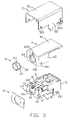
- FIG. 3 is an exploded view of the electrical connector shown in FIG. 1 ;
- FIG. 4 is a perspective view of a cover of the electrical connector shown in FIG. 1 ;
- FIG. 5 is a perspective view of the cover with a sleeve mounted therein.
- FIG. 6 is another perspective view of the cover with the sleeve mounted therein.
- an electrical connector 100 according to the preferred embodiment of the present invention is provided and comprises an insulating housing 1 , a plurality of terminals 2 mounted in the housing 1 , a sleeve 3 mounted in the housing 1 , a cover 4 fastening the sleeve 3 and mounted on the housing 1 , a shell 5 surrounding the housing 1 and the cover 4 , and a flake 6 attached to a mating face 11 of the housing 1 .
- the insulating housing 1 defines a receiving cavity 10 running through the mating face 11 thereby defining an opening 101 for guiding a mating plug to be inserted.
- a recess portion 111 is defined around the opening 101 and recessed rearward, with a gap 112 defined at an upper portion of the housing and communicating with the receiving cavity 10 .
- a grounding terminal 2 is fixed in an upper wall of the housing and includes a contacting portion 21 projecting into the receiving cavity through the gap 112 .
- Each side wall of the insulating housing 1 is in a step configuration and comprises a first side wall 12 at a front end thereof and a second side wall 13 at a rear end and protruding outward.
- Each first and second side walls 12 , 13 form a protrusion portion 121 , 131 protruding outward for locking with the shell 5 .
- the metallic sleeve 3 includes an annular base portion 32 and a ring 31 extending forward from the base portion 32 , wherein the ring is in a smaller dimension than the base portion 32 .
- a hole 311 is defined on the sleeve 3 corresponding with the gap 112 on the insulating housing 1 .
- the cover 4 includes a rectangular body portion 41 , a pair of side wall 42 extending downward from opposite side edges of the body portion 41 , a front wall 43 extending downward from a front edge of the body portion 41 and connecting with the side wall 42 , thereby defining a space surrounded by the three walls.
- An aperture 430 is defined on the front wall 43 for receiving the sleeve 3 and in communication with the space, and an annular extending portion 431 projecting forward from circumference of the aperture 430 .
- a slot 4311 corresponding with the hole 311 is defined at a joint portion of the body portion 41 and front wall 43 .
- a plurality of ribs 4312 are provided in an inner side wall of the extending portion 431 for improving the interfering force.
- the sleeve 3 is inserted into the cover 4 from a rear end, the ring 31 of the sleeve 3 projects forward and exposes to an exterior of the extending portion 431 by running through the aperture 430 , meanwhile, circumference of the ring 31 is interfering with the ribs 4312 on the extending portion 431 for retention, and the base portion 32 is blocked by a rear end of the extending portion 431 (i.e. an inner face 432 of the front wall 43 ) for preventing the forward movement of the sleeve 3 .
- the slot 4311 on the extending portion 431 is aligned with the hole 311 on the ring 31 at this time, therefore, the sleeve 3 is primarily mounted on the cover 4 .
- the cover 4 together with the sleeve 3 is assembled onto the insulating housing 1 .
- the side walls 42 of the cover 4 are tightly affixed to the first walls 12 with rear ends abutting against front ends of the second walls 13 , and the protrusion portions 121 , 131 of the first and second walls 12 , 13 are received in apertures 421 defined at lower ends of the side walls 42 .
- the front wall 43 is tightly affixed to the mating face 11 of the housing 1 with the base portion 32 received in the recess portion 111 and the contacting portion 21 of the contact 2 projecting into the hole 311 on the sleeve and slot 4311 on the extending portion.
- the body portion 41 covers the upper wall of the housing 1 and sandwiches the terminal 2 together with the upper wall of the housing. Under this condition, the sleeve 3 is finally retained between the cover 4 and the insulating housing 1 , and can not move toward any direction. Then, the shell 5 is assembled onto the housing 1 with a top wall 51 covering the base portion 41 of the cover 4 , locking holes 521 , 522 defined on each side wall 52 being locked with corresponding protrusion portions 121 , 131 , and a rear wall 53 shielding the rear ends of the housing 1 and cover 4 . Finally, the flake 6 is attached onto the front wall 43 of the cover 4 for beautiful looking, therefore, an integral electrical connector has been made with steadily retention effect.
- the sleeve 3 is primarily assembled onto a cover 4 and then assembled onto the housing 1 so that the sleeve 3 is sandwiched between the housing 1 and the cover 4 and can not release from the housing easily.
Abstract
Description
Claims (13)
Applications Claiming Priority (3)
| Application Number | Priority Date | Filing Date | Title |
|---|---|---|---|
| CN200820300644.2 | 2008-04-28 | ||
| CN200820300644U | 2008-04-28 | ||
| CNU2008203006442U CN201252232Y (en) | 2008-04-28 | 2008-04-28 | Electric connector |
Publications (2)
| Publication Number | Publication Date |
|---|---|
| US20090269982A1 US20090269982A1 (en) | 2009-10-29 |
| US7717753B2 true US7717753B2 (en) | 2010-05-18 |
Family
ID=40747902
Family Applications (1)
| Application Number | Title | Priority Date | Filing Date |
|---|---|---|---|
| US12/387,106 Expired - Fee Related US7717753B2 (en) | 2008-04-28 | 2009-04-28 | Electrical connector with a sleeve therein |
Country Status (2)
| Country | Link |
|---|---|
| US (1) | US7717753B2 (en) |
| CN (1) | CN201252232Y (en) |
Cited By (3)
| Publication number | Priority date | Publication date | Assignee | Title |
|---|---|---|---|---|
| US20090305571A1 (en) * | 2008-06-04 | 2009-12-10 | Hon Hai Precision Industry Co., Ltd. | Electrical connector with improved housing |
| US7887376B1 (en) * | 2010-04-09 | 2011-02-15 | Cheng Uei Precision Industry Co., Ltd. | Audio jack connector |
| US20160056591A1 (en) * | 2014-08-22 | 2016-02-25 | Foxconn Interconnect Technology Limited | Electrical connector having sidewardly exposed contacts |
Citations (3)
| Publication number | Priority date | Publication date | Assignee | Title |
|---|---|---|---|---|
| US6551127B1 (en) | 2001-12-26 | 2003-04-22 | Hon Hai Precision Ind. Co., Ltd. | Socket connector having additional ring |
| US20080076303A1 (en) * | 2006-09-22 | 2008-03-27 | Hon Hai Precision Ind. Co., Ltd. | Electrical connector |
| US7530813B1 (en) * | 2008-08-18 | 2009-05-12 | Suyin Electronics (Dongguan) Co., Ltd. | Coaxial connector |
-
2008
- 2008-04-28 CN CNU2008203006442U patent/CN201252232Y/en not_active Expired - Lifetime
-
2009
- 2009-04-28 US US12/387,106 patent/US7717753B2/en not_active Expired - Fee Related
Patent Citations (3)
| Publication number | Priority date | Publication date | Assignee | Title |
|---|---|---|---|---|
| US6551127B1 (en) | 2001-12-26 | 2003-04-22 | Hon Hai Precision Ind. Co., Ltd. | Socket connector having additional ring |
| US20080076303A1 (en) * | 2006-09-22 | 2008-03-27 | Hon Hai Precision Ind. Co., Ltd. | Electrical connector |
| US7530813B1 (en) * | 2008-08-18 | 2009-05-12 | Suyin Electronics (Dongguan) Co., Ltd. | Coaxial connector |
Cited By (5)
| Publication number | Priority date | Publication date | Assignee | Title |
|---|---|---|---|---|
| US20090305571A1 (en) * | 2008-06-04 | 2009-12-10 | Hon Hai Precision Industry Co., Ltd. | Electrical connector with improved housing |
| US7867037B2 (en) * | 2008-06-04 | 2011-01-11 | Hon Hai Precision Ind. Co., Ltd. | Electrical connector with terminals retained on external faces of the housing |
| US7887376B1 (en) * | 2010-04-09 | 2011-02-15 | Cheng Uei Precision Industry Co., Ltd. | Audio jack connector |
| US20160056591A1 (en) * | 2014-08-22 | 2016-02-25 | Foxconn Interconnect Technology Limited | Electrical connector having sidewardly exposed contacts |
| US9520685B2 (en) * | 2014-08-22 | 2016-12-13 | Foxconn Interconnect Technology Limited | Electrical connector having sidewardly exposed contacts |
Also Published As
| Publication number | Publication date |
|---|---|
| US20090269982A1 (en) | 2009-10-29 |
| CN201252232Y (en) | 2009-06-03 |
Similar Documents
| Publication | Publication Date | Title |
|---|---|---|
| US7927108B2 (en) | Power socket with anti-mismating means | |
| US8961235B2 (en) | Electrical connector with improved mating member having anti-mismating portion for preventing incorrect insertion | |
| US8475216B2 (en) | Electrical connector having mating interface configured by composite tongue member | |
| US7618286B2 (en) | Shield connector | |
| US9431746B2 (en) | USB connector assembly | |
| US6447311B1 (en) | Electrical connector with grounding means | |
| US20080299827A1 (en) | Electrical connector with metal shell having convex hull extending from the surface of the front portion thereof | |
| US7654866B2 (en) | Upright electrical connector | |
| US7485013B2 (en) | Electrical connector assembly having improved cover | |
| WO2012043542A1 (en) | Connector and electronic device | |
| US7824192B2 (en) | Electrical connector having two engaging portions | |
| US8562376B2 (en) | Cable connector assembly having a capacitor connected with one connector and a metallic shell | |
| US7530844B2 (en) | Electrical connector with retaining member | |
| US8348700B1 (en) | Cable connector having a metallic shield slidably disposed in a groove | |
| US7147505B2 (en) | Connector assembly with strain relief member | |
| US8465296B1 (en) | Electrical connector | |
| US7510431B2 (en) | Electrical connector with improved board locks | |
| US8403698B2 (en) | Cable assembly with an improved grounding device | |
| US6168467B1 (en) | Receptacle connector | |
| US10826255B2 (en) | Flippable electrical connector | |
| US6280252B1 (en) | Electrical connector firmly retaining an insulative housing | |
| US6471546B1 (en) | Electrical connector | |
| US6821151B2 (en) | Cable end connector assembly | |
| US6234828B1 (en) | Electrical connector assembly with improved locking means | |
| US6210231B1 (en) | Electrical connector |
Legal Events
| Date | Code | Title | Description |
|---|---|---|---|
| AS | Assignment |
Owner name: HON HAI PRECISION IND. CO., LTD., TAIWAN Free format text: ASSIGNMENT OF ASSIGNORS INTEREST;ASSIGNOR:CHEN, ZHI-QIANG;REEL/FRAME:022651/0692 Effective date: 20090422 Owner name: HON HAI PRECISION IND. CO., LTD.,TAIWAN Free format text: ASSIGNMENT OF ASSIGNORS INTEREST;ASSIGNOR:CHEN, ZHI-QIANG;REEL/FRAME:022651/0692 Effective date: 20090422 |
|
| FPAY | Fee payment |
Year of fee payment: 4 |
|
| FEPP | Fee payment procedure |
Free format text: MAINTENANCE FEE REMINDER MAILED (ORIGINAL EVENT CODE: REM.) |
|
| LAPS | Lapse for failure to pay maintenance fees |
Free format text: PATENT EXPIRED FOR FAILURE TO PAY MAINTENANCE FEES (ORIGINAL EVENT CODE: EXP.) |
|
| STCH | Information on status: patent discontinuation |
Free format text: PATENT EXPIRED DUE TO NONPAYMENT OF MAINTENANCE FEES UNDER 37 CFR 1.362 |
|
| FP | Lapsed due to failure to pay maintenance fee |
Effective date: 20180518 |