US12157157B2 - Pressing machine and pressed product manufacturing method - Google Patents
Pressing machine and pressed product manufacturing method Download PDFInfo
- Publication number
- US12157157B2 US12157157B2 US17/617,806 US202117617806A US12157157B2 US 12157157 B2 US12157157 B2 US 12157157B2 US 202117617806 A US202117617806 A US 202117617806A US 12157157 B2 US12157157 B2 US 12157157B2
- Authority
- US
- United States
- Prior art keywords
- die
- pressing machine
- workpiece
- ram
- press die
- Prior art date
- Legal status (The legal status is an assumption and is not a legal conclusion. Google has not performed a legal analysis and makes no representation as to the accuracy of the status listed.)
- Active, expires
Links
- 238000003825 pressing Methods 0.000 title claims abstract description 98
- 238000004519 manufacturing process Methods 0.000 title claims description 15
- 230000007246 mechanism Effects 0.000 claims abstract description 50
- 230000033001 locomotion Effects 0.000 claims abstract description 38
- 238000006243 chemical reaction Methods 0.000 claims abstract description 18
- 125000006850 spacer group Chemical group 0.000 claims description 113
- 238000005259 measurement Methods 0.000 claims description 16
- 238000007599 discharging Methods 0.000 claims 4
- 238000010409 ironing Methods 0.000 description 11
- 239000002184 metal Substances 0.000 description 10
- 238000013461 design Methods 0.000 description 8
- 239000011295 pitch Substances 0.000 description 7
- 230000000149 penetrating effect Effects 0.000 description 6
- 238000012937 correction Methods 0.000 description 4
- 230000008878 coupling Effects 0.000 description 4
- 238000010168 coupling process Methods 0.000 description 4
- 238000005859 coupling reaction Methods 0.000 description 4
- 230000006835 compression Effects 0.000 description 2
- 238000007906 compression Methods 0.000 description 2
- 230000000694 effects Effects 0.000 description 2
- 238000003754 machining Methods 0.000 description 2
- 239000000463 material Substances 0.000 description 2
- 238000012546 transfer Methods 0.000 description 2
- 230000004323 axial length Effects 0.000 description 1
- 230000005540 biological transmission Effects 0.000 description 1
- 239000003638 chemical reducing agent Substances 0.000 description 1
- 238000010586 diagram Methods 0.000 description 1
- 230000006870 function Effects 0.000 description 1
- 230000002093 peripheral effect Effects 0.000 description 1
- 238000002360 preparation method Methods 0.000 description 1
- 238000004080 punching Methods 0.000 description 1
Images


Classifications
-
- B—PERFORMING OPERATIONS; TRANSPORTING
- B21—MECHANICAL METAL-WORKING WITHOUT ESSENTIALLY REMOVING MATERIAL; PUNCHING METAL
- B21D—WORKING OR PROCESSING OF SHEET METAL OR METAL TUBES, RODS OR PROFILES WITHOUT ESSENTIALLY REMOVING MATERIAL; PUNCHING METAL
- B21D22/00—Shaping without cutting, by stamping, spinning, or deep-drawing
- B21D22/02—Stamping using rigid devices or tools
-
- B—PERFORMING OPERATIONS; TRANSPORTING
- B21—MECHANICAL METAL-WORKING WITHOUT ESSENTIALLY REMOVING MATERIAL; PUNCHING METAL
- B21D—WORKING OR PROCESSING OF SHEET METAL OR METAL TUBES, RODS OR PROFILES WITHOUT ESSENTIALLY REMOVING MATERIAL; PUNCHING METAL
- B21D22/00—Shaping without cutting, by stamping, spinning, or deep-drawing
- B21D22/20—Deep-drawing
- B21D22/28—Deep-drawing of cylindrical articles using consecutive dies
-
- B—PERFORMING OPERATIONS; TRANSPORTING
- B21—MECHANICAL METAL-WORKING WITHOUT ESSENTIALLY REMOVING MATERIAL; PUNCHING METAL
- B21D—WORKING OR PROCESSING OF SHEET METAL OR METAL TUBES, RODS OR PROFILES WITHOUT ESSENTIALLY REMOVING MATERIAL; PUNCHING METAL
- B21D22/00—Shaping without cutting, by stamping, spinning, or deep-drawing
- B21D22/20—Deep-drawing
- B21D22/30—Deep-drawing to finish articles formed by deep-drawing
-
- B—PERFORMING OPERATIONS; TRANSPORTING
- B21—MECHANICAL METAL-WORKING WITHOUT ESSENTIALLY REMOVING MATERIAL; PUNCHING METAL
- B21D—WORKING OR PROCESSING OF SHEET METAL OR METAL TUBES, RODS OR PROFILES WITHOUT ESSENTIALLY REMOVING MATERIAL; PUNCHING METAL
- B21D24/00—Special deep-drawing arrangements in, or in connection with, presses
- B21D24/005—Multi-stage presses
-
- B—PERFORMING OPERATIONS; TRANSPORTING
- B21—MECHANICAL METAL-WORKING WITHOUT ESSENTIALLY REMOVING MATERIAL; PUNCHING METAL
- B21D—WORKING OR PROCESSING OF SHEET METAL OR METAL TUBES, RODS OR PROFILES WITHOUT ESSENTIALLY REMOVING MATERIAL; PUNCHING METAL
- B21D37/00—Tools as parts of machines covered by this subclass
- B21D37/04—Movable or exchangeable mountings for tools
-
- B—PERFORMING OPERATIONS; TRANSPORTING
- B21—MECHANICAL METAL-WORKING WITHOUT ESSENTIALLY REMOVING MATERIAL; PUNCHING METAL
- B21D—WORKING OR PROCESSING OF SHEET METAL OR METAL TUBES, RODS OR PROFILES WITHOUT ESSENTIALLY REMOVING MATERIAL; PUNCHING METAL
- B21D37/00—Tools as parts of machines covered by this subclass
- B21D37/14—Particular arrangements for handling and holding in place complete dies
-
- B—PERFORMING OPERATIONS; TRANSPORTING
- B21—MECHANICAL METAL-WORKING WITHOUT ESSENTIALLY REMOVING MATERIAL; PUNCHING METAL
- B21D—WORKING OR PROCESSING OF SHEET METAL OR METAL TUBES, RODS OR PROFILES WITHOUT ESSENTIALLY REMOVING MATERIAL; PUNCHING METAL
- B21D43/00—Feeding, positioning or storing devices combined with, or arranged in, or specially adapted for use in connection with, apparatus for working or processing sheet metal, metal tubes or metal profiles; Associations therewith of cutting devices
- B21D43/003—Positioning devices
-
- B—PERFORMING OPERATIONS; TRANSPORTING
- B21—MECHANICAL METAL-WORKING WITHOUT ESSENTIALLY REMOVING MATERIAL; PUNCHING METAL
- B21D—WORKING OR PROCESSING OF SHEET METAL OR METAL TUBES, RODS OR PROFILES WITHOUT ESSENTIALLY REMOVING MATERIAL; PUNCHING METAL
- B21D43/00—Feeding, positioning or storing devices combined with, or arranged in, or specially adapted for use in connection with, apparatus for working or processing sheet metal, metal tubes or metal profiles; Associations therewith of cutting devices
- B21D43/02—Advancing work in relation to the stroke of the die or tool
- B21D43/04—Advancing work in relation to the stroke of the die or tool by means in mechanical engagement with the work
- B21D43/05—Advancing work in relation to the stroke of the die or tool by means in mechanical engagement with the work specially adapted for multi-stage presses
-
- B—PERFORMING OPERATIONS; TRANSPORTING
- B21—MECHANICAL METAL-WORKING WITHOUT ESSENTIALLY REMOVING MATERIAL; PUNCHING METAL
- B21D—WORKING OR PROCESSING OF SHEET METAL OR METAL TUBES, RODS OR PROFILES WITHOUT ESSENTIALLY REMOVING MATERIAL; PUNCHING METAL
- B21D51/00—Making hollow objects
- B21D51/02—Making hollow objects characterised by the structure of the objects
- B21D51/10—Making hollow objects characterised by the structure of the objects conically or cylindrically shaped objects
-
- B—PERFORMING OPERATIONS; TRANSPORTING
- B30—PRESSES
- B30B—PRESSES IN GENERAL
- B30B15/00—Details of, or accessories for, presses; Auxiliary measures in connection with pressing
- B30B15/14—Control arrangements for mechanically-driven presses
-
- B—PERFORMING OPERATIONS; TRANSPORTING
- B30—PRESSES
- B30B—PRESSES IN GENERAL
- B30B15/00—Details of, or accessories for, presses; Auxiliary measures in connection with pressing
- B30B15/26—Programme control arrangements
-
- B—PERFORMING OPERATIONS; TRANSPORTING
- B21—MECHANICAL METAL-WORKING WITHOUT ESSENTIALLY REMOVING MATERIAL; PUNCHING METAL
- B21D—WORKING OR PROCESSING OF SHEET METAL OR METAL TUBES, RODS OR PROFILES WITHOUT ESSENTIALLY REMOVING MATERIAL; PUNCHING METAL
- B21D45/00—Ejecting or stripping-off devices arranged in machines or tools dealt with in this subclass
- B21D45/003—Ejecting or stripping-off devices arranged in machines or tools dealt with in this subclass in punching machines or punching tools
- B21D45/006—Stripping-off devices
-
- B—PERFORMING OPERATIONS; TRANSPORTING
- B21—MECHANICAL METAL-WORKING WITHOUT ESSENTIALLY REMOVING MATERIAL; PUNCHING METAL
- B21D—WORKING OR PROCESSING OF SHEET METAL OR METAL TUBES, RODS OR PROFILES WITHOUT ESSENTIALLY REMOVING MATERIAL; PUNCHING METAL
- B21D45/00—Ejecting or stripping-off devices arranged in machines or tools dealt with in this subclass
- B21D45/02—Ejecting devices
- B21D45/04—Ejecting devices interrelated with motion of tool
Definitions
- the present disclosure relates to a pressing machine and a pressed product manufacturing method using the pressing machine.
- Known pressing machines include a pressing machine for drawing, ironing, or crushing a workpiece (see, for example, Patent Literature 1).
- the thickness, position, and shape of a portion to be worked of a workpiece change little by little due to thermal expansion of a press die or the like during continuous operation, and the workpiece may eventually become a reject.
- the pressing machine is temporarily stopped, holding of the press die by a die holding portion is loosened, and the position of the press die is adjusted.
- the conventional pressing machine requires such troublesome work, and thus has had a problem of decrease in production efficiency.
- the present disclosure therefore provides a pressing machine and a pressed product manufacturing method capable of improving production efficiency as compared with a conventional art.
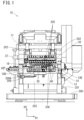
- FIG. 1 is a front view of a pressing machine according to a first embodiment.
- FIG. 2 is a partially broken perspective view of a die holding portion of a ram.
- FIG. 3 is a front view of the die holding portion of the ram.
- FIG. 4 is a sectional side view of a die holding portion of a bolster and a punch at a bottom dead center.
- FIG. 6 is a perspective view of a position adjustment mechanism.
- FIG. 7 is a block diagram of a control system of the pressing machine.
- FIG. 9 is a sectional side view of a position adjustment mechanism of a pressing machine according to a third embodiment.
- FIG. 10 is a sectional side view of a position adjustment mechanism of a pressing machine according to a fourth embodiment.
- FIG. 11 is a sectional side view of a position adjustment mechanism of a pressing machine according to a fifth embodiment.
- FIG. 1 illustrates the entire pressing machine 10 of the present embodiment.
- the lateral direction in FIG. 1 is referred to as a lateral direction H 1 of the pressing machine 10
- the direction perpendicular to a paper surface of FIG. 1 is referred to as a front-rear direction H 2 (corresponding to the “second direction” in the claims, see FIG. 2 ) of the pressing machine 10
- the vertical direction in FIG. 1 is referred to as a vertical direction H 3 (corresponding to the “first direction” in the claims) of the pressing machine 10
- FIG. 1 shows a front side of the pressing machine 10 , and the opposite side is referred to as a rear side.
- the right side and the left side in FIG. 1 are simply referred to as the right side and the left side of the pressing machine 10 or the like.
- the bolster support beam 203 has, for example, a quadrangular cross section, extends in the lateral direction H 1 , and is laid between positions close to lower ends of the pair of opposing walls 202 .
- a slit (not illustrated) penetrating in the vertical direction H 3 is formed at the center of the bolster support beam 203 in the front-rear direction H 2 . Then, a bolster 13 is fitted and fixed to an upper surface of the bolster support beam 203 .
- the ram support wall has a plate shape with its thickness direction in the front-rear direction H 2 , and is laid between rear edge portions of opposing surfaces of the pair of opposing walls 202 , above the level of the center of the pair of opposing walls 202 in the vertical direction. Then, a ram 20 is slidably attached to a front surface of the ram support wall.
- a cam shaft 71 is laid between and rotatably supported by positions close to upper ends of the pair of opposing walls 202 . Then, the ram 20 receives power from the cam shaft 71 , and repeats an up-and-down motion.
- a press die of the pressing machine 10 of the present embodiment includes a plurality of punches 30 and a plurality of dies 40 .
- a plurality of die holding portions 205 is provided at a bottom portion of the ram 20 so as to be arranged at a constant pitch in the lateral direction H 1 .
- a plurality of die holding portions 206 is provided at an upper surface of the bolster 13 so as to be arranged at a constant pitch in the lateral direction H 1 . Then, the plurality of punches 30 and the plurality of dies 40 face each other in a plurality of pairs, the punch 30 and the die 40 of each pair constitute a working stage ST, and a workpiece 90 is pressed in each working stage ST.
- the workpiece 90 is generated from sheet metal by a workpiece feeder 18 disposed further on the left side of the working stage ST at the left end.
- a punching die (not illustrated) is supported by a frame 18 D and is disposed so as to be suspended above the die holding portions 206 .
- the workpiece feeder 18 is provided with a punch 18 P having a nesting structure in which a cylindrical second punch is fitted outside a first punch (not illustrated), and the punch 18 P is attached to the ram 20 .
- the sheet metal is fed from the rear by pitch feeding, a blank material is punched out of the sheet metal by the second punch, and the blank material is drawn by the first punch to generate a cylindrical workpiece 90 .
- the workpiece 90 formed by the pressing machine 10 of the present embodiment has, for example, a cylindrical shape with one end closed and the other end open, and has a through hole 91 A at the center of a bottom wall 91 .
- the plurality of punches 30 has a columnar shape, and the die 40 is provided with a punch receiving hole 41 H having a circular cross section. Then, in each working stage ST, the punch 30 pushes the workpiece 90 into the punch receiving hole 41 H of the die 40 for drawing, ironing, crushing, or the like.
- some of the working stages ST are provided with a mechanism for causing a tool to advance and retract toward and from the workpiece 90 in the front-rear direction H 2 .
- a mechanism for causing a tool to advance and retract toward and from the workpiece 90 in the front-rear direction H 2 is provided with a mechanism for causing a tool to advance and retract toward and from the workpiece 90 in the front-rear direction H 2 .
- a through hole or an engraved mark is formed on the workpiece 90 from the front, or an upper edge portion of the workpiece 90 is removed.
- a through hole 13 H penetrating the bolster 13 in the vertical direction is provided coaxially with and below the punch receiving hole 41 H of each die 40 , and a knockout pin 16 is received in each through hole 13 H.
- a lower end portion of the knockout pin 16 protrudes downward from the slit of the bolster support beam 203 described above.
- a position close to the lower end of the knockout pin 16 penetrates a support plate 203 A (see FIG. 6 ) fixed to the bolster support beam 203 .
- a compression coil spring 16 C (see FIG. 6 ) is disposed around a portion of the knockout pin 16 above the level of the support plate 203 A.
- each knockout pin 16 is pushed and lowered by the punch 30 via the workpiece 90 , and is also raised by elastic reaction force of the compression coil spring 16 C and power received at the lower end portion as necessary.
- a movable die 42 is provided between the workpiece 90 and the knockout pin 16 , and the knockout pin 16 presses the workpiece 90 toward the punch 30 via the movable die 42 .
- a stripper 33 is fitted on an intermediate position in the vertical direction H 3 of the punch 30 . Then, the workpiece 90 which is discharged from the die 40 together with the punch 30 , is separated from the punch 30 by the stripper 33 .
- a lever 19 provided behind the bolster 13 is coupled to each stripper 33 , and the stripper 33 is moved up and down with respect to the corresponding punch 30 by the lever 19 in synchronization with the up-and-down motion of the ram 20 .
- the pressing machine 10 is provided with a workpiece conveying device 209 that conveys a workpiece 90 to each working stage ST.
- a workpiece conveying device 209 that conveys a workpiece 90 to each working stage ST.
- the pressing machine that sequentially conveys the workpiece 90 to the plurality of working stages ST is generally called a “transfer pressing machine”, and the workpiece conveying device 209 in this case is generally called a “transfer device”.
- the workpiece conveying device 209 has a pair of rails 209 A (only one of the rails 209 A is illustrated in FIG. 1 ) extending in the lateral direction H 1 on the plurality of die holding portions 206 and facing each other in the front-rear direction H 2 .
- a plurality of pairs of fingers 17 is arranged and supported in the lateral direction H 1 at a constant pitch as illustrated in FIG. 2 .
- the pair of fingers 17 are biased toward each other by a coil spring (not illustrated).
- a lower end portion of the stripper 33 enters between the pair of fingers 17 from above or from a side, thereby opening the pair of fingers 17 .
- each pair of fingers 17 grips the workpiece 90 and conveys the workpiece 90 to the right side in FIG. 1 by a certain pitch.
- the workpiece 90 generated by the workpiece feeder 18 is sequentially conveyed to each working stage ST, and machining is performed on the workpiece 90 at a plurality of times.
- the workpiece 90 is discharged from the working stage ST at the right end to, for example, a chute (not illustrated).
- the workpiece feeder 18 and the working stage ST at the left end are separated by a distance of two pitches, and a dummy stage where machining is not performed is provided therebetween.
- the lever 19 that drives the workpiece conveying device 209 , the workpiece feeder 18 , and the stripper 33 is mechanically coupled to the cam shaft 71 , and receives power from a servomotor 70 , which is a power source used in common with the ram 20 .
- the shape of the workpiece 90 slightly differs depending on a difference in positions where the punches 30 and the dies 40 are held by the die holding portions 205 , 206 .
- the die holding portions 205 of the ram 20 are provided with a mechanism for adjusting the positions where the punches 30 are held.
- a structure of the die holding portions 205 of the ram 20 will be described in detail.
- the plurality of die holding portions 205 of the ram 20 is provided on a support base 21 fixed to the bottom portion of the ram 20 .
- the support base 21 has a vertical rear surface, and a rear protrusion 21 B protrudes toward the rear from a lower portion of the rear surface. Then, the rear surface of the support base 21 is fitted to a lower portion of a front surface of the ram 20 , and an upper surface of the rear protrusion 21 B is fitted to a lower surface of the ram 20 and is fixed to the ram 20 .
- the ram 20 has a stepped surface 20 C formed by recessing a lower end portion of the front surface, and a rear edge portion of an upper surface of the support base 21 is fitted to the stepped surface 20 C.
- the support base 21 has a front surface having a stepped portion 21 D at an intermediate position in the vertical direction, and a lower stage portion 21 E (see FIG. 3 ) below the stepped portion 21 D is recessed from an upper stage portion 21 F which is located above.
- a plurality of screw holes 23 A penetrating vertically is formed in the upper stage portion 21 F of the support base 21 so as to be arranged at a constant pitch in the lateral direction H 1 .
- an adjustment bolt 24 is screwed into each screw hole 23 A, and a lower end portion thereof protrudes toward a longitudinal groove 22 described below.
- a tool engagement portion 24 H (see FIG. 6 ) constituted by a hexagonal hole, a hexagonal shaft portion, or the like for engaging a tool for a screwing operation is formed at an upper end portion of the adjustment bolt 24 .
- the support base 21 has a plurality of screw holes 23 B formed to communicate between a front surface of the upper stage portion 21 F and the corresponding screw holes 23 A, and set screws (not illustrated) are screwed into the screw holes 23 B to prevent the adjustment bolt 24 from rotating.
- a plurality of the longitudinal grooves 22 is formed immediately below the plurality of screw holes 23 A in the lower stage portion 21 E of the support base 21 .
- the longitudinal grooves 22 have a square groove structure with a quadrangular cross section, and are open on the front side and the bottom side.
- a pair of screw holes 22 N are arranged vertically between adjacent longitudinal grooves 22 in the lower stage portion 21 E.
- only a lower screw hole 22 N of the pair of screw holes 22 N described above is provided on the right of the longitudinal groove 22 at the right end, and only an upper screw hole 22 N of the pair of screw holes 22 N is provided on the left of the longitudinal groove 22 at the left end.
- an adapter 31 is received in each longitudinal groove 22 .
- the adapter 31 is constituted by a circular through hole 31 A formed at the center of a prismatic body extending in the vertical direction H 3 .
- a through hole 31 B penetrating from a front surface to the through hole 31 A is formed at a position in the middle in the vertical direction of the adapter 31 , and part of a locking member 31 C fitted thereto protrudes into the through hole 31 A.
- Each adapter 31 just fits in the corresponding longitudinal groove 22 in the lateral direction H 1 , and slightly protrudes toward the front from an opening on a front surface of the longitudinal groove 22 . Then, for the purpose of fixing each adapter 31 to the corresponding longitudinal groove 22 , a plurality of pressing members 25 extending obliquely from top left to bottom right as viewed from the front is disposed so as to obliquely cross the opening on the front surface of each longitudinal groove 22 , and bolts (not illustrated) penetrating both ends of each pressing member 25 are screwed into the screw holes 22 N described above.
- Each punch 30 is fitted and held in the through hole 31 A of the corresponding adapter 31 described above.
- the punch 30 extends from an upper end to at least a position close to a lower end with a circular cross section, and an upper portion of the punch 30 serves as a held portion 30 A to be fitted in the through hole 31 A of the adapter 31 .
- a head portion 30 H protrudes laterally from an upper end of the held portion 30 A and is fitted to an upper surface of the adapter 31 .
- a locking groove 30 B in the shape of a square groove extending in the vertical direction H 3 is formed on a peripheral surface of the held portion 30 A. Then, part of the locking member 31 C described above is engaged with the locking groove 30 B so that the punch 30 is prevented from rotating with respect to the adapter 31 .
- a gas release hole 30 G extends from a distal end surface to a position close to the distal end, and a lateral hole (not illustrated) communicates between an upper end portion of the gas release hole 30 G and an outer surface of the punch 30 .
- the plurality of die holding portions 205 of the ram 20 of the present embodiment is constituted by the adapter 31 , the longitudinal groove 22 , the pressing member 25 , and the like described above. Then, the punch 30 is positioned in the vertical direction H 3 with respect to the ram 20 by the adjustment bolt 24 disposed above each die holding portion 205 .
- the bolts fixing the pressing member 25 are loosened, and the punch 30 is set so as to abut on the adjustment bolt 24 slightly above a target position. Then, an operation of tightening the adjustment bolt 24 may be performed so that the adapter 31 is lowered together with the punch 30 and moved to the target position.
- the plurality of dies 40 attached to the bolster 13 of the pressing machine 10 of the present embodiment includes a crushing die 40 , a drawing die 40 , and an ironing die 40 .
- the crushing die 40 is constituted by the fixed die 41 and a movable die 42
- the drawing die 40 and the ironing die 40 are constituted by only a fixed die 41 .
- the fixed die 41 has a rectangular parallelepiped shape, and the punch receiving hole 41 H illustrated in FIG. 4 vertically penetrates the center thereof.
- the punch receiving hole 41 H of each of the drawing die 40 and the ironing die 40 is reduced in diameter at an intermediate position in the axial direction, and is provided with a reduced diameter portion (not illustrated) for drawing or ironing the workpiece 90 .
- the punch receiving hole 41 H of the crushing die 40 is, for example, uniform in inner diameter.
- the die 40 illustrated in FIGS. 4 and 5 is the crushing die 40 .
- the movable die 42 of the crushing die 40 has an upper portion that is just fitted in the punch receiving hole 41 H and can be moved up and down, and has a lower end flange 42 B protruding laterally from a lower end portion, so as not to come out upward from the punch receiving hole 41 H.
- a portion of the movable die 42 above the level of the lower end flange 42 B is substantially the same in axial length as the punch receiving hole 41 H.
- a recess 13 B is formed on the upper surface of the bolster 13 by recessing the entire surface except for both ends in the lateral direction H 1 in a stepped manner. Then, a plurality of support blocks 14 is housed and fixed side by side in the recess 13 B.
- a die receiving recess 51 having a quadrangular planar shape is formed on an upper surface of each support block 14 .
- a guide hole 52 vertically penetrating the support block 14 is formed at the center of a bottom surface of the die receiving recess 51 , and screw holes (not illustrated) are formed at four corners of the bottom surface of the die receiving recess 51 .
- the fixed die 41 included in each die 40 just fits in the die receiving recess 51 , and is fixed with a bolt. That is, the inside of the support block 14 serves as the die holding portion 206 .
- the guide hole 52 of the die holding portion 206 for crushing has an inner diameter larger than that of the punch receiving hole 41 H of the die 40 , and a guide sleeve 43 is fitted inside the guide hole 52 .
- the guide sleeve 43 has a cylindrical shape that just fits in the guide hole 52 , and has an inner diameter that is slightly larger than the inner diameter of the punch receiving hole 41 H and is just the size for the lower end flange 42 B of the movable die 42 to fit in.
- a slight gap is provided between an upper surface of the guide sleeve 43 and the fixed die 41 .
- a lower end portion of the guide sleeve 43 slightly protrudes into a square hole 53 which will be described below.
- the guide sleeve 43 is fitted inside the guide hole 52 of the die holding portion 206 , and the movable die 42 is slidably fitted in the guide sleeve 43 (corresponding to the “slide support portion” in the claims).
- a configuration may be adopted in which the guide sleeve 43 is not provided, the guide hole 52 of the die holding portion 206 has the same inner diameter as the guide sleeve 43 , and the movable die 42 is slidably fitted directly to the guide hole 52 .
- the square hole 53 is formed coaxially with and below the guide hole 52 .
- the square hole 53 has a planar shape that is, for example, a square in which a circle which is a planar shape of the guide hole 52 , is inscribed as viewed in the vertical direction H 3 .
- a second spacer 46 is fitted in the square hole 53 .
- the second spacer 46 has a square plate shape just fitted in the square hole 53 , and a through hole 46 H smaller than the inner diameter of the guide sleeve 43 is formed at the center thereof as illustrated in FIG. 4 .
- An upper surface of the second spacer 46 serves as an abutting surface 46 N perpendicular to central axes of the guide sleeve 43 and the movable die 42 , and is in surface abutment with lower surfaces of the guide sleeve 43 and the movable die 42 .
- a lower surface of the second spacer 46 serves as an abutting slope 46 M having a slight inclination angle with respect to the central axes of the guide sleeve 43 and the movable die 42 , and is inclined downward toward the rear in the front-rear direction H 2 , for example.
- a stepped lower surface recess 54 is formed on a lower surface of the support block 14 , and the square hole 53 is opened in an upper surface in the lower surface recess 54 .
- a plate-shaped sliding metal 38 is fixed to a position of the bolster 13 facing the lower surface recess 54 .
- a first spacer 45 is received in the lower surface recess 54 , and the first spacer 45 and the second spacer 46 described above constitute a spacer set 44 (corresponding to the “die positioning portion” and the “portion for die positioning” in the claims).
- the movable die 42 and the guide sleeve 43 are positioned at lower ends of their movable ranges in accordance with the position of an upper surface of the spacer set 44 (the abutting surface 46 N of the second spacer 46 ).
- a lower surface of the first spacer 45 forms a flat surface perpendicular to the central axes of the guide sleeve 43 and the movable die 42 , and is in surface abutment with an upper surface of the sliding metal 38 .
- an upper surface of the first spacer 45 serves as an abutting slope 45 M having a slight inclination angle with respect to the central axes of the guide sleeve 43 and the movable die 42 , and is inclined downward toward the rear in the front-rear direction H 2 , so as to be in surface abutment with the abutting slope 46 M of the second spacer 46 .
- the lower surface recess 54 has a pair of opposing surfaces (not illustrated) parallel to the front-rear direction H 2 , and the first spacer 45 is guided by the pair of opposing surfaces to slide in the lower surface recess 54 .
- the first spacer 45 moves toward the rear in the lower surface recess 54 , and the abutting slopes 45 M and 46 M of the first spacer 45 and the second spacer 46 come into sliding contact with each other, so that the upper surface of the second spacer 46 (that is, the upper surface of the spacer set 44 ) is raised.
- the first spacer 45 moves toward the front in the lower surface recess 54 , and the abutting slopes 45 M and 46 M of the first spacer 45 and the second spacer 46 come into sliding contact with each other, so that the upper surface of the second spacer 46 (that is, the upper surface of the spacer set 44 ) is lowered, and the positions where the movable die 42 and the guide sleeve 43 are positioned by the spacer set 44 are changed.
- a movable component housing space 14 K communicating with the lower surface recess 54 is formed in the support block 14 on the front side of the guide hole 52 . Then, the movable component housing space 14 K receives a coupling wall 45 B standing upright from a front end portion of the first spacer 45 .
- a support housing 61 is fixed to a front surface of the support block 14 , and the movable component housing space 14 K is also provided in the support housing 61 . Then, rear end portions of a pair of coupling beams 67 extending in the front-rear direction H 2 across the support block 14 and the support housing 61 are fixed to both side portions of the coupling wall 45 B, and a movement amount confirming member 66 is fixed in a state of being sandwiched between front end portions of the pair of coupling beams 67 .
- a nut (not illustrated) is fixed to the movement amount confirming member 66 , and a screw portion provided on an outer surface of a rotation shaft (not illustrated) extending in the front-rear direction H 2 is screwed into the nut.
- the support housing 61 is provided with a pair of shaft support walls 65 so that the movable component housing space 14 K is partitioned in the front-rear direction H 2 .
- the movement amount confirming member 66 is disposed between the pair of shaft support walls 65 , and a rear end portion and a position close to a front end of the rotation shaft are rotatably supported by the pair of shaft support walls 65 so as not to be movable in the front-rear direction H 2 .
- a bevel gear unit 62 is fixed to a front surface of the support housing 61 , an output portion of the bevel gear unit 62 and a front end portion of the rotation shaft are coupled by a joint 62 J, and a servomotor 63 is coupled to an input shaft (not illustrated) provided on a lower surface of the bevel gear unit 62 via a speed reducer 63 G.
- the first spacer 45 is slid in the front-rear direction H 2 by the servomotor 63 , and the position of a bottom dead center of the movable die 42 in the vertical direction H 3 can be adjusted.
- the servomotor 63 , the first spacer 45 , the second spacer 46 , the nut, the rotation shaft, and the like constitute a position adjustment mechanism 68 that adjusts the position of the movable die 42 .
- the position adjustment mechanism 68 described above can be operated by a controller 100 of the pressing machine 10 .
- a memory 101 of the controller 100 stores data regarding a rotation amount of the servomotor 63 corresponding to an amount of movement of the upper surface of the spacer set 44 in the vertical direction H 3 .
- a CPU 103 of the controller 100 functions as a drive control unit 104 , and a target rotation amount of the servomotor 63 corresponding to the position change data is determined.
- an output portion of the servomotor 63 is rotationally driven so as to move to a target position, which is away from the current rotational position by the target rotation amount.
- the upper surface of the spacer set 44 is moved upward or downward from the current position corresponding to the input position change data, and the position where the movable die 42 is positioned by the spacer set 44 is changed.
- the drive control unit 104 drives the servomotor 63 while reaction force due to press working from the movable die 42 is not applied to the spacer set 44 in a state where the continuous operation is continued. Specifically, while the rotational position of the cam shaft 71 is within a prescribed range (e.g., a range of ⁇ 120 to +60) from the position where the ram 20 is at a top dead center, the drive control unit 104 starts driving the servomotor 63 , and ends the driving of the servomotor 63 before the ram 20 reaches a bottom dead center.
- a prescribed range e.g., a range of ⁇ 120 to +60
- a movable range of the movable die 42 in the vertical direction H 3 by the position adjustment mechanism 68 of the present embodiment is 1 [mm] or less, and resolution of that movement is 0.1 [mm] or less (e.g., in units of 0.01 [mm]).
- the thicknesses of the bottom walls 91 of the several workpieces 90 are actually measured, and in a case where the difference between the actual measurement value and the design value exceeds a reference value, the position of the punch 30 is adjusted by the adjustment bolt 24 of the working stage ST having the position adjustment mechanism 68 so that the difference does not exceed the reference value. Then, after the adjustment, the pressing machine 10 is continuously operated, and the workpieces 90 are mass-produced as pressed products. Also during the continuous operation, the thickness of the bottom wall 91 of the workpiece 90 is actually measured as a sample every time the number of pressed products manufactured reaches a predetermined number.
- the punch 30 or the movable die 42 may be thermally deformed by frictional heat and gradually extend in the vertical direction H 3 , and the bottom wall 91 of the workpiece 90 may gradually become thinner than that at the beginning of the continuous operation of the pressing machine 10 .
- the bottom wall 91 of the workpiece 90 may become thicker than that at the beginning of the continuous operation of the pressing machine 10 .
- position change data for reducing the difference between the actual measurement value and the design value of the thickness of the bottom wall 91 may be input to the controller 100 in the console 102 .
- the difference of the actual measurement value with respect to the design value of the bottom wall 91 is +0.3 [mm]
- ⁇ 0.3 [mm] may be input to the controller 100 as position change data.
- the drive control unit 104 drives the servomotor 63 to slide the first spacer 45 to the rear side, so that the upper surface of the spacer set 44 is raised by 0.3 [mm].
- the pressing machine 10 and the pressed product manufacturing method using the pressing machine 10 of the present embodiment it is possible to quickly and easily perform operation of correcting the position of a press die (movable die 42 ) in the die holding portion 206 without performing conventional troublesome manual work of loosening holding of the press die by the die holding portion and adjusting the position of the press die, and it is possible to improve the production efficiency and reduce a manufacturing cost as compared with a conventional art.
- the correction can be performed in a state where continuous operation of the pressing machine 10 is maintained, and this greatly improves the production efficiency.
- the position correction is performed when reaction force due to press working from the movable die 42 is not applied to the spacer set 44 , and this stabilizes results of the position correction on the dimensions of the workpiece 90 .
- a pressing machine 10 A of the present embodiment is illustrated in FIG. 8 , and includes a position adjustment mechanism 68 A which is different from that of the pressing machine 10 of the first embodiment.
- the position adjustment mechanism 68 A is different from the position adjustment mechanism 68 of the first embodiment only in that a guide sleeve 43 slightly protrudes toward a die receiving recess 51 of a support block 14 . Then, the position adjustment mechanism 68 A changes both of the positions where a fixed die 41 and a movable die 42 are positioned by the spacer set 44 .
- a pressing machine 10 B of the present embodiment is illustrated in FIG. 9 , and in the pressing machine 10 A of the second embodiment, a stepped portion 41 D is provided on an inner surface of a punch receiving hole 41 H of a fixed die 41 , the position of which can be adjusted by the position adjustment mechanism 68 A, and a stepped portion 30 D is provided on an outer surface of a punch 30 .
- a stepped wall 93 provided at an intermediate position in the axial direction of the workpiece 90 is sandwiched between the stepped portions 30 D and 41 D of the punch 30 and the fixed die 41 for crushing.
- a pressing machine 10 C of the present embodiment is illustrated in FIG. 10 , and is provided with a position adjustment mechanism 68 C in any of working stages ST for performing, for example, drawing or ironing of the pressing machine 10 of the first embodiment.
- a through hole 46 H having an inner diameter larger than that of a guide sleeve 43 is formed in a second spacer 46 of the position adjustment mechanism 68 C. Then, a head portion 16 B of a knockout pin 16 passes through the inside of the guide sleeve 43 , and abuts on a bottom wall 91 of a workpiece 90 .
- the second spacer 46 Z has, for example, a quadrangular planar shape, and is provided with a lower surface protrusion 46 T having a circular cross section protruding downward. Then, the lower surface protrusion 46 T is fitted in a spacer fitting portion 31 Z formed by expanding an upper portion of a through hole 31 A of an adapter 31 .
- the auxiliary spacer 47 has a disk shape, is fitted in the spacer fitting portion 31 Z, and is fitted to a lower surface of the lower surface protrusion 46 T. Then, an upper end portion of a punch 30 slightly protrudes into the spacer fitting portion 31 Z and abuts on the auxiliary spacer 47 .
- Each of a lower surface of the second spacer 46 Z, an upper surface and a lower surface of the auxiliary spacer 47 , and an upper surface of the punch 30 forms a horizontal plane perpendicular to a vertical direction H 3 , which is a moving direction of the ram 20 .
- the first spacer 45 Z has, for example, a quadrangular planar shape. Both side surfaces of the first spacer 45 Z and the second spacer 46 Z are disposed flush with each other, and are adjacent to both inner side surfaces (not illustrated) of the recess 21 G. Then, a lower surface of the first spacer 45 Z and an upper surface of the second spacer 46 Z are in surface abutment with each other as abutting slopes 45 M and 46 M both inclined with respect to the vertical direction H 3 and a front-rear direction H 2 .
- the sliding metal 38 Z is fitted and fixed to a lower surface of the upper stage portion 21 F, which is also an upper surface in the recess 21 G. Then, an upper surface of the first spacer 45 Z and a lower surface of the sliding metal 38 Z both form a horizontal plane perpendicular to the vertical direction H 3 and are in surface abutment with each other.
- the first spacer 45 Z moves in the front-rear direction H 2 , so that the second spacer 46 Z moves in the vertical direction H 3 .
- a screw hole 45 J extending in the front-rear direction H 2 is formed in the first spacer 45 Z, and a screw portion 48 N provided at a rear end portion of a rotation shaft 48 is screwed into the screw hole 45 J.
- the rotation shaft 48 is rotatably supported, at a position close to a front end, so as not to be movable in the front-rear direction H 2 , by a bracket 49 fixed to a front surface of the upper stage portion 21 F.
- a servomotor 63 Z is attached to a front surface of the bracket 49 , and a rotation output portion of the servomotor 63 Z and a front end portion of the rotation shaft 48 are coupled via a pair of bevel gears 48 G.
- the spacer set 44 Z is provided with the auxiliary spacer 47 separately from the first spacer 45 Z and the second spacer 46 Z, and this makes it possible to easily handle a plurality of types of workpieces by changing the auxiliary spacer 47 .
- an operator determines position change data on the basis of an actual measurement result of a designated location of a workpiece 90 , and manually inputs the position change data to the controller 100 .
- the designated location of the workpiece 90 may be automatically actually measured, and then the position change data may be automatically determined on the basis of the actual measurement result and given to the drive control unit 104 .
- the position change data may be automatically determined on the basis of measurement of a temperature of a punch 30 or a die 40 or the number of times a ram 20 moves up and down as a substitute value for the actual measurement.
- the cylindrical workpiece 90 of the first embodiment has a circular planar cross section, but the planar cross section may be elliptical or polygonal (e.g., a quadrangle or a hexagon).
- the workpiece 90 may not have a cylindrical shape, and may have, for example, a shallow dish shape or a plate shape.
- the nut and the rotation shaft are provided as main components as a “motion conversion mechanism” that converts a rotational output of the servomotor 63 or 63 Z into a relative movement between the first spacer 45 or 45 Z and the second spacer 46 or 46 Z.
- the “motion conversion mechanism” may be a ball screw mechanism, a cam mechanism, or a crank mechanism.
- the rotational output of the servomotor 63 may be converted into a linear movement in the moving direction of the ram 20 by the “motion conversion mechanism” described above, and the position where the press die (punch 30 and die 40 ) is positioned by the die positioning portion (spacer set 44 or 44 Z) may be changed.
- the direction of the linear movement is changed by the first spacer 45 and the second spacer 46 as in the embodiments, transmission of reaction force due to press working is suppressed between the first spacer 45 and the second spacer 46 , and load on the servomotor 63 can be reduced.
- the position of the press die is corrected by the position adjustment mechanism 68 during continuous operation of the pressing machine 10 .
- the correction may be performed while the pressing machine 10 is stopped.
- the position adjustment mechanism 68 is provided only in one die holding portion 206 , but may be provided in a plurality of die holding portions.
Landscapes
- Engineering & Computer Science (AREA)
- Mechanical Engineering (AREA)
- Shaping Metal By Deep-Drawing, Or The Like (AREA)
- Mounting, Exchange, And Manufacturing Of Dies (AREA)
- Press Drives And Press Lines (AREA)
- Presses And Accessory Devices Thereof (AREA)
Abstract
Description
-
- Patent Literature 1: JP 2016-203212 A (paragraph [0021], FIG. 1)
-
- 10, 10A to 10D Pressing machine
- 13 Bolster
- 16 Knockout pin
- 20 Ram
- 30 Punch
- 40 Die
- 41 Fixed die
- 42 Movable die
- 44, 44Z Spacer set
- 45, 45Z First spacer
- 45M, 46M Abutting slope
- 46, 46Z Second spacer
- 47 Auxiliary spacer
- 63, 63Z Servomotor
- 68, 68A, 68C, 68D Position adjustment mechanism
- 90 Workpiece
- 91 Bottom wall
- 104 Drive control unit
- 205, 206 Die holding portion
- 209 Workpiece conveying device
- 209A Rail
- H2 Front-rear direction (second direction)
- H3 Vertical direction (first direction)
- ST Working stage
Claims (22)
Applications Claiming Priority (3)
| Application Number | Priority Date | Filing Date | Title |
|---|---|---|---|
| JP2020014494A JP6840448B1 (en) | 2020-01-31 | 2020-01-31 | Press machine and manufacturing method of pressed products |
| JP2020-014494 | 2020-01-31 | ||
| PCT/JP2021/001660 WO2021153344A1 (en) | 2020-01-31 | 2021-01-19 | Press and manufacturing method for pressed product |
Publications (2)
| Publication Number | Publication Date |
|---|---|
| US20220241835A1 US20220241835A1 (en) | 2022-08-04 |
| US12157157B2 true US12157157B2 (en) | 2024-12-03 |
Family
ID=74845318
Family Applications (1)
| Application Number | Title | Priority Date | Filing Date |
|---|---|---|---|
| US17/617,806 Active 2041-12-02 US12157157B2 (en) | 2020-01-31 | 2021-01-19 | Pressing machine and pressed product manufacturing method |
Country Status (6)
| Country | Link |
|---|---|
| US (1) | US12157157B2 (en) |
| EP (1) | EP3984665A4 (en) |
| JP (1) | JP6840448B1 (en) |
| KR (1) | KR102595481B1 (en) |
| CN (1) | CN113891769B (en) |
| WO (1) | WO2021153344A1 (en) |
Families Citing this family (6)
| Publication number | Priority date | Publication date | Assignee | Title |
|---|---|---|---|---|
| JP7004441B1 (en) | 2021-10-06 | 2022-01-21 | 旭精機工業株式会社 | Punch positioning jig and transfer press machine |
| JP7210124B1 (en) | 2022-03-30 | 2023-01-23 | 旭精機工業株式会社 | press machine |
| KR102681239B1 (en) | 2022-09-28 | 2024-07-02 | 이용철 | Small press units for inline processes |
| CN117399509B (en) * | 2023-12-11 | 2024-04-05 | 上海治臻新能源股份有限公司 | Draw bead and stamping die |
| CN119588812B (en) * | 2025-02-05 | 2025-07-18 | 四川汇才铝业有限公司 | A stamping and stretching device for aluminum material processing |
| CN120306468B (en) * | 2025-06-13 | 2025-08-29 | 广州源方精密压铸科技股份有限公司 | Anti-skinning method based on high-compactness exhaust stamping die technology |
Citations (13)
| Publication number | Priority date | Publication date | Assignee | Title |
|---|---|---|---|---|
| US2279417A (en) | 1940-01-27 | 1942-04-14 | Carlton R Stevens | Multiple punch press |
| GB789408A (en) | 1954-11-23 | 1958-01-22 | Johan Willem Ocenasek | Improvements in or relating to punching apparatus |
| DE2743642A1 (en) | 1976-09-29 | 1978-03-30 | K M Engineering Ag | Transfer press for producing aerosol containers - has separate hydraulic drive to each punch connected by self-aligning joint |
| JPS61276722A (en) | 1985-05-30 | 1986-12-06 | Noritsu Kikai Seisakusho:Kk | Transfer press apparatus |
| US4736612A (en) * | 1987-02-17 | 1988-04-12 | Power Brake Dies, Inc. | Compensating die holder |
| CN1129639A (en) | 1994-10-04 | 1996-08-28 | 村田机械株式会社 | Press drive control device |
| JP2002331318A (en) | 2001-05-08 | 2002-11-19 | Citizen Electronics Co Ltd | Die for manufacturing belleville spring |
| EP2486993A1 (en) | 2011-02-11 | 2012-08-15 | HINTERKOPF GmbH | Reshaping device and method for operating same |
| US20160059296A1 (en) | 2014-08-27 | 2016-03-03 | Benteler Automobiltechnik Gmbh | Press-forming tool with tolerance compensation |
| US20160114381A1 (en) | 2014-10-27 | 2016-04-28 | Tyco Electronics Corporation | Press device with adjustment mechanism |
| CN106064194A (en) | 2015-04-23 | 2016-11-02 | 旭精机工业株式会社 | Multiple position press |
| JP2018153823A (en) | 2017-03-15 | 2018-10-04 | 旭精機工業株式会社 | Press machine and press machine modification set |
| US20190118242A1 (en) | 2016-04-28 | 2019-04-25 | Fritz Werner Industrie-Ausrüstungen Gmbh | Transfer press having a c-shaped ram |
-
2020
- 2020-01-31 JP JP2020014494A patent/JP6840448B1/en active Active
-
2021
- 2021-01-19 KR KR1020217038298A patent/KR102595481B1/en active Active
- 2021-01-19 CN CN202180003445.3A patent/CN113891769B/en active Active
- 2021-01-19 EP EP21748210.8A patent/EP3984665A4/en active Pending
- 2021-01-19 US US17/617,806 patent/US12157157B2/en active Active
- 2021-01-19 WO PCT/JP2021/001660 patent/WO2021153344A1/en not_active Ceased
Patent Citations (17)
| Publication number | Priority date | Publication date | Assignee | Title |
|---|---|---|---|---|
| US2279417A (en) | 1940-01-27 | 1942-04-14 | Carlton R Stevens | Multiple punch press |
| GB789408A (en) | 1954-11-23 | 1958-01-22 | Johan Willem Ocenasek | Improvements in or relating to punching apparatus |
| DE2743642A1 (en) | 1976-09-29 | 1978-03-30 | K M Engineering Ag | Transfer press for producing aerosol containers - has separate hydraulic drive to each punch connected by self-aligning joint |
| JPS61276722A (en) | 1985-05-30 | 1986-12-06 | Noritsu Kikai Seisakusho:Kk | Transfer press apparatus |
| US4736612A (en) * | 1987-02-17 | 1988-04-12 | Power Brake Dies, Inc. | Compensating die holder |
| CN1129639A (en) | 1994-10-04 | 1996-08-28 | 村田机械株式会社 | Press drive control device |
| US5706711A (en) | 1994-10-04 | 1998-01-13 | Murata Kikai Kabushiki Kaisha | Punch drive control apparatus |
| JP2002331318A (en) | 2001-05-08 | 2002-11-19 | Citizen Electronics Co Ltd | Die for manufacturing belleville spring |
| EP2486993A1 (en) | 2011-02-11 | 2012-08-15 | HINTERKOPF GmbH | Reshaping device and method for operating same |
| US20160059296A1 (en) | 2014-08-27 | 2016-03-03 | Benteler Automobiltechnik Gmbh | Press-forming tool with tolerance compensation |
| CN105382098A (en) | 2014-08-27 | 2016-03-09 | 本特勒尔汽车技术有限公司 | Press-forming tool with tolerance compensation |
| US20160114381A1 (en) | 2014-10-27 | 2016-04-28 | Tyco Electronics Corporation | Press device with adjustment mechanism |
| CN105680284A (en) | 2014-10-27 | 2016-06-15 | 泰科电子公司 | Press device with adjustment mechanism |
| CN106064194A (en) | 2015-04-23 | 2016-11-02 | 旭精机工业株式会社 | Multiple position press |
| JP2016203212A (en) | 2015-04-23 | 2016-12-08 | 旭精機工業株式会社 | Transfer press machin |
| US20190118242A1 (en) | 2016-04-28 | 2019-04-25 | Fritz Werner Industrie-Ausrüstungen Gmbh | Transfer press having a c-shaped ram |
| JP2018153823A (en) | 2017-03-15 | 2018-10-04 | 旭精機工業株式会社 | Press machine and press machine modification set |
Non-Patent Citations (5)
| Title |
|---|
| Dec. 8, 2020 Office Action issued in Japanese Patent Application No. 2020-014494. |
| Feb. 10, 2023 Office Action issued in Chinese Patent Application No. 202180003445.3. |
| Feb. 16, 2021 International Search Report issued in International Patent Application No. PCT/JP2021/001660. |
| Sep. 11, 2024, Search Report issued in European Patent Application No. 21748210.8. |
| Sep. 9, 2022, Search Report issued in European Patent Application No. 21748210.8. |
Also Published As
| Publication number | Publication date |
|---|---|
| EP3984665A4 (en) | 2022-10-12 |
| US20220241835A1 (en) | 2022-08-04 |
| EP3984665A1 (en) | 2022-04-20 |
| KR102595481B1 (en) | 2023-10-30 |
| WO2021153344A1 (en) | 2021-08-05 |
| JP2021120161A (en) | 2021-08-19 |
| JP6840448B1 (en) | 2021-03-10 |
| CN113891769B (en) | 2023-09-05 |
| KR20220002457A (en) | 2022-01-06 |
| CN113891769A (en) | 2022-01-04 |
Similar Documents
| Publication | Publication Date | Title |
|---|---|---|
| US12157157B2 (en) | Pressing machine and pressed product manufacturing method | |
| US20100122563A1 (en) | Method and apparatus for forming bend-controlling straps in sheet material | |
| CN109396266B (en) | Pre-forging deep bending die | |
| JPH07314045A (en) | Bending device | |
| US20180133774A1 (en) | System and method for bending metal including tandem press brakes | |
| CN105964763A (en) | Punching production main machine | |
| JP2000140955A (en) | Press device | |
| KR101583607B1 (en) | Apparatus for forming thin plate and manufacturing method using the same | |
| CN211360345U (en) | Secondary bending die based on U-shaped sheet metal part | |
| US8356396B2 (en) | Method for making threaded tube | |
| KR100723623B1 (en) | Fine Blanking Press Screw Stopper Device | |
| CN1655892A (en) | Insertion devices especially for automatic rolling mills | |
| KR100952716B1 (en) | A backlash less fine blanking press screw stopper equipment | |
| CN107159955B (en) | Accurate shearing blanking device | |
| CN120734167B (en) | An inward bending device for metal sheets | |
| US5381681A (en) | Machine with an adjusting device located in a movable machine part | |
| CN215657366U (en) | Thick plate boss stretching forming die | |
| CN110449515A (en) | A multi-functional trimming mold | |
| CN120116289B (en) | New energy automobile right instrument board end cover die-cut mould | |
| CN220479955U (en) | Sheet metal part stamping die shearing device | |
| CN111215523A (en) | A bracket bending forming device | |
| JP2536808Y2 (en) | Punch adjusting device for multi-stage press forming machine | |
| CN121402515A (en) | Be used for C shaped steel and U shaped steel web and wing edge trompil to flatten integration equipment | |
| JP2755430B2 (en) | Progressive processing equipment | |
| JP3053696U (en) | Punch adjusting device for multi-stage press forming machine |
Legal Events
| Date | Code | Title | Description |
|---|---|---|---|
| AS | Assignment |
Owner name: ASAHI-SEIKI MANUFACTURING CO., LTD., JAPAN Free format text: ASSIGNMENT OF ASSIGNORS INTEREST;ASSIGNORS:MORI, FUJIO;KOBAYASHI, SEIJI;SHIINO, AKIHIRO;AND OTHERS;SIGNING DATES FROM 20211025 TO 20211026;REEL/FRAME:058350/0382 |
|
| FEPP | Fee payment procedure |
Free format text: ENTITY STATUS SET TO UNDISCOUNTED (ORIGINAL EVENT CODE: BIG.); ENTITY STATUS OF PATENT OWNER: LARGE ENTITY |
|
| STPP | Information on status: patent application and granting procedure in general |
Free format text: DOCKETED NEW CASE - READY FOR EXAMINATION |
|
| STPP | Information on status: patent application and granting procedure in general |
Free format text: NON FINAL ACTION MAILED |
|
| STPP | Information on status: patent application and granting procedure in general |
Free format text: RESPONSE TO NON-FINAL OFFICE ACTION ENTERED AND FORWARDED TO EXAMINER |
|
| STPP | Information on status: patent application and granting procedure in general |
Free format text: NOTICE OF ALLOWANCE MAILED -- APPLICATION RECEIVED IN OFFICE OF PUBLICATIONS |
|
| STPP | Information on status: patent application and granting procedure in general |
Free format text: NOTICE OF ALLOWANCE MAILED -- APPLICATION RECEIVED IN OFFICE OF PUBLICATIONS |
|
| STPP | Information on status: patent application and granting procedure in general |
Free format text: NOTICE OF ALLOWANCE MAILED -- APPLICATION RECEIVED IN OFFICE OF PUBLICATIONS |
|
| STPP | Information on status: patent application and granting procedure in general |
Free format text: NOTICE OF ALLOWANCE MAILED -- APPLICATION RECEIVED IN OFFICE OF PUBLICATIONS |
|
| STPP | Information on status: patent application and granting procedure in general |
Free format text: PUBLICATIONS -- ISSUE FEE PAYMENT RECEIVED |
|
| STPP | Information on status: patent application and granting procedure in general |
Free format text: PUBLICATIONS -- ISSUE FEE PAYMENT VERIFIED |
|
| STCF | Information on status: patent grant |
Free format text: PATENTED CASE |