US12143717B2 - Information processing apparatus, information processing method, and program - Google Patents
Information processing apparatus, information processing method, and program Download PDFInfo
- Publication number
- US12143717B2 US12143717B2 US17/912,436 US202117912436A US12143717B2 US 12143717 B2 US12143717 B2 US 12143717B2 US 202117912436 A US202117912436 A US 202117912436A US 12143717 B2 US12143717 B2 US 12143717B2
- Authority
- US
- United States
- Prior art keywords
- shooting
- target
- shooting apparatus
- basis
- information processing
- Prior art date
- Legal status (The legal status is an assumption and is not a legal conclusion. Google has not performed a legal analysis and makes no representation as to the accuracy of the status listed.)
- Active, expires
Links
Images


Classifications
-
- G—PHYSICS
- G06—COMPUTING OR CALCULATING; COUNTING
- G06T—IMAGE DATA PROCESSING OR GENERATION, IN GENERAL
- G06T7/00—Image analysis
- G06T7/50—Depth or shape recovery
- G06T7/55—Depth or shape recovery from multiple images
- G06T7/593—Depth or shape recovery from multiple images from stereo images
-
- H—ELECTRICITY
- H04—ELECTRIC COMMUNICATION TECHNIQUE
- H04N—PICTORIAL COMMUNICATION, e.g. TELEVISION
- H04N23/00—Cameras or camera modules comprising electronic image sensors; Control thereof
- H04N23/60—Control of cameras or camera modules
- H04N23/67—Focus control based on electronic image sensor signals
- H04N23/675—Focus control based on electronic image sensor signals comprising setting of focusing regions
-
- G—PHYSICS
- G06—COMPUTING OR CALCULATING; COUNTING
- G06T—IMAGE DATA PROCESSING OR GENERATION, IN GENERAL
- G06T7/00—Image analysis
- G06T7/20—Analysis of motion
-
- G—PHYSICS
- G06—COMPUTING OR CALCULATING; COUNTING
- G06T—IMAGE DATA PROCESSING OR GENERATION, IN GENERAL
- G06T7/00—Image analysis
- G06T7/70—Determining position or orientation of objects or cameras
-
- G—PHYSICS
- G06—COMPUTING OR CALCULATING; COUNTING
- G06V—IMAGE OR VIDEO RECOGNITION OR UNDERSTANDING
- G06V10/00—Arrangements for image or video recognition or understanding
- G06V10/10—Image acquisition
- G06V10/12—Details of acquisition arrangements; Constructional details thereof
- G06V10/14—Optical characteristics of the device performing the acquisition or on the illumination arrangements
-
- G—PHYSICS
- G06—COMPUTING OR CALCULATING; COUNTING
- G06V—IMAGE OR VIDEO RECOGNITION OR UNDERSTANDING
- G06V10/00—Arrangements for image or video recognition or understanding
- G06V10/70—Arrangements for image or video recognition or understanding using pattern recognition or machine learning
- G06V10/74—Image or video pattern matching; Proximity measures in feature spaces
- G06V10/761—Proximity, similarity or dissimilarity measures
-
- H—ELECTRICITY
- H04—ELECTRIC COMMUNICATION TECHNIQUE
- H04N—PICTORIAL COMMUNICATION, e.g. TELEVISION
- H04N23/00—Cameras or camera modules comprising electronic image sensors; Control thereof
- H04N23/60—Control of cameras or camera modules
- H04N23/61—Control of cameras or camera modules based on recognised objects
-
- H—ELECTRICITY
- H04—ELECTRIC COMMUNICATION TECHNIQUE
- H04N—PICTORIAL COMMUNICATION, e.g. TELEVISION
- H04N23/00—Cameras or camera modules comprising electronic image sensors; Control thereof
- H04N23/60—Control of cameras or camera modules
- H04N23/63—Control of cameras or camera modules by using electronic viewfinders
- H04N23/633—Control of cameras or camera modules by using electronic viewfinders for displaying additional information relating to control or operation of the camera
-
- H—ELECTRICITY
- H04—ELECTRIC COMMUNICATION TECHNIQUE
- H04N—PICTORIAL COMMUNICATION, e.g. TELEVISION
- H04N23/00—Cameras or camera modules comprising electronic image sensors; Control thereof
- H04N23/60—Control of cameras or camera modules
- H04N23/66—Remote control of cameras or camera parts, e.g. by remote control devices
- H04N23/661—Transmitting camera control signals through networks, e.g. control via the Internet
-
- H—ELECTRICITY
- H04—ELECTRIC COMMUNICATION TECHNIQUE
- H04N—PICTORIAL COMMUNICATION, e.g. TELEVISION
- H04N23/00—Cameras or camera modules comprising electronic image sensors; Control thereof
- H04N23/60—Control of cameras or camera modules
- H04N23/67—Focus control based on electronic image sensor signals
-
- H—ELECTRICITY
- H04—ELECTRIC COMMUNICATION TECHNIQUE
- H04N—PICTORIAL COMMUNICATION, e.g. TELEVISION
- H04N23/00—Cameras or camera modules comprising electronic image sensors; Control thereof
- H04N23/90—Arrangement of cameras or camera modules, e.g. multiple cameras in TV studios or sports stadiums
Definitions
- the present technology relates to an information processing apparatus, an information processing method, and a program, and particularly relates to an information processing apparatus, an information processing method, and a program suitable for use in a case of focusing a shooting apparatus.
- focus of the camera is adjusted on the basis of a distance (hereinafter, referred to as subject distance) to a subject of target to be focused (hereinafter, referred to as shooting target).
- the user in a case of manually adjusting the focus, the user roughly adjusts the focus by estimating the distance to the shooting target. Next, the user finely adjusts the focus while viewing the image generated by the imaging element of the camera or the image of the shooting target formed by the lens.
- the subject distance to the shooting target is measured by a ranging sensor provided in the vicinity of the camera, and the focus of the camera is adjusted on the basis of the measured subject distance (see, for example, Patent Document 1).
- the ranging sensor has advantages and disadvantages depending on the type. For example, depending on the type of ranging sensor, the range in which the distance can be measured is narrowed, the resolution of the distance measurement is rough, or the distance measurement is easily affected by sunlight. Therefore, it is not always possible to accurately focus on the shooting target, and there is a case where the accuracy of focus decreases depending on the situation.
- the present technology has been made in view of such a situation, and an object thereof is to improve accuracy of automatic adjustment of focus of a shooting apparatus without using a ranging sensor.
- An information processing apparatus includes: a position detection section that detects a distance between a first shooting apparatus and a shooting target on the basis of a positional relationship among the first shooting apparatus, a second shooting apparatus, and the shooting target, which is a target to be focused; and a focus control section that controls focus of the first shooting apparatus on the basis of a distance between the first shooting apparatus and the shooting target.
- An information processing method includes: detecting a distance between a first shooting apparatus and a shooting target on the basis of a positional relationship among the first shooting apparatus, a second shooting apparatus, and the shooting target; and controlling focus of the first shooting apparatus on the basis of a distance between the first shooting apparatus and the shooting target.
- a program causes a computer to execute processing of detecting a distance between a first shooting apparatus and a shooting target on the basis of a positional relationship among the first shooting apparatus, a second shooting apparatus, and the shooting target, and controlling focus of the first shooting apparatus on the basis of a distance between the first shooting apparatus and the shooting target.
- a distance between a first shooting apparatus and a shooting target is detected on the basis of a positional relationship among the first shooting apparatus, a second shooting apparatus, and the shooting target, and focus of the first shooting apparatus is controlled on the basis of a distance between the first shooting apparatus and the shooting target.
- FIG. 1 is a block diagram illustrating a configuration example of an information processing system to which the present technology is applied.
- FIG. 2 is a block diagram illustrating a configuration example of a shooting apparatus.
- FIG. 3 is a block diagram illustrating a configuration example of an information processing section of the shooting apparatus.
- FIG. 4 is a block diagram illustrating a configuration example of an information processing apparatus.
- FIG. 5 is a block diagram illustrating a configuration example of an information processing section of the information processing apparatus.
- FIG. 6 is a flowchart for explaining position detection processing.
- FIG. 7 is a view for explaining a calculation method of external parameters of the shooting apparatus.
- FIG. 8 is a flowchart for explaining focus control processing.
- FIG. 9 is a view illustrating an example of a positional relationship between each shooting apparatus and a shooting target.
- FIG. 10 is a view for explaining a calculation method of a subject distance.
- FIG. 11 is a view for explaining the calculation method of the subject distance.
- FIG. 12 is a view for explaining the calculation method of the subject distance.
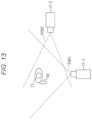
- FIG. 13 is a view illustrating an example of a target to be focused.
- FIG. 14 is a view illustrating an example of a positional relationship between each shooting apparatus and the shooting target.
- FIG. 15 is a view illustrating an example of a positional relationship between each shooting apparatus and the shooting target.
- FIG. 16 is a view illustrating an example of a display method of shooting target information.
- FIG. 17 is a view illustrating an example of the display method of shooting target information.
- FIG. 1 illustrates a configuration example of an embodiment of an information processing system 1 to which the present technology is applied.
- the information processing system 1 includes shooting apparatuses 11 - 1 to 11 - 3 and an information processing apparatus 12 .
- the shooting apparatuses 11 - 1 to 11 - 3 and the information processing apparatus 12 are connected to one another via a network configured in a wired or/and wireless manner, and exchange various data.
- shooting apparatus 11 in a case where it is not necessary to individually distinguish the shooting apparatuses 11 - 1 to 11 - 3 , they are simply referred to as shooting apparatus 11 .
- FIG. 1 illustrates a case where three shooting apparatuses 11 are installed, but the present technology can be applied as long as there are at least two shooting apparatuses 11 , and can also be applied to a case where there are four or more shooting apparatuses 11 .
- the shooting apparatus 11 shoots a still image or a moving image, and transmits image data corresponding to the shot still image or moving image to the information processing apparatus 12 .
- the shooting apparatus 11 only needs to include at least a focus automatic adjustment function to be described later, and a method and a type thereof are not particularly limited.
- the image represents an image for one frame constituting a still image or a moving image shot by the shooting apparatus 11 .
- the information processing apparatus 12 By analyzing an image shot by each of the shooting apparatuses 11 , the information processing apparatus 12 detects a positional relationship between each of the shooting apparatuses 11 and a subject (shooting target) to be a target to be focused by each of the shooting apparatuses 11 . Furthermore, the information processing apparatus 12 adjusts focus of each of the shooting apparatuses 11 on the basis of the positional relationship between each of the shooting apparatuses 11 and the shooting target.
- FIG. 2 illustrates a configuration example of the shooting apparatus 11 .
- the shooting apparatus 11 includes an optical system 101 , an imaging element 102 , a digital signal processor (DSP) 103 , a central processing unit (CPU) 104 , a display unit 105 , an operation system 106 , a frame memory 107 , a recording unit 108 , a power supply system 109 , a communication unit 110 , and the like.
- the optical system 101 to the communication unit 110 are connected to one another via a bus 121 .
- the optical system 101 includes a lens system and the like, captures incident light (image light) from the subject, and forms an image of the subject on an imaging surface of the imaging element 102 . Furthermore, the optical system 101 is driven by the CPU 104 to adjust focus of the shooting apparatus 11 .
- the imaging element 102 converts the amount of incident light incident on the imaging surface by the optical system 101 into an electrical signal in units of pixels, and supplies it to the DSP 103 as a pixel signal.
- an imaging element of discretionary type can be used as the imaging element 102 .
- the DSP 103 performs various processing on the pixel signal supplied from the imaging element 102 , and generates, on the frame memory 107 , image data corresponding to the image shot by the imaging element 102 .
- the CPU 104 controls each unit of the shooting apparatus 11 .
- the display unit 105 includes a panel type display unit such as a liquid crystal display unit or an organic electro luminescence (EL) display unit, for example.
- the display unit 105 displays a still image or a moving image shot by, for example, the imaging element 102 , an operation screen, and the like.
- the operation system 106 includes, for example, various operation devices and is used for operation of the shooting apparatus 11 .
- the operation system 106 generates and outputs, to the bus 121 , an operation signal based on a user operation.
- the recording unit 108 records image data or the like, for example, generated by the DSP 103 onto a recording medium such as a hard disk drive (HDD) or a digital versatile disk (DVD).
- a recording medium such as a hard disk drive (HDD) or a digital versatile disk (DVD).
- the power supply system 109 supplies power necessary for the operation of each unit of the shooting apparatus 11 .
- the communication unit 110 communicates with the information processing apparatus 12 by a predetermined communication method.
- bus 121 in a case where each unit exchanges data and the like via the bus 121 in the shooting apparatus 11 is omitted.
- the description of the bus 121 is omitted, and it is described simply that the CPU 104 and the communication unit 110 perform communication.
- FIG. 3 illustrates a configuration example of the information processing section 151 , which is a function implemented by the CPU 104 executing a program.
- the information processing section 151 includes a focus control section 161 and a display control section 162 .
- the focus control section 161 adjusts focus of the shooting apparatus 11 by driving the optical system 101 on the basis of, for example, a focus control signal received from the information processing apparatus 12 , an auto focus (AF) function included in the focus control section 161 , or ac operation signal supplied from the operation system 106 .
- a focus control signal received from the information processing apparatus 12
- an auto focus (AF) function included in the focus control section 161 or ac operation signal supplied from the operation system 106 .
- the display control section 162 controls display of various images by the display unit 105 .
- FIG. 4 illustrates a configuration example of hardware of the information processing apparatus 12 .
- the information processing apparatus 12 includes, for example, a computer.
- a CPU 201 a read only memory (ROM) 202 , and a random access memory (RAM) 203 are connected to one another via a bus 204 .
- An input/output interface 205 is further connected to the bus 204 .
- An input unit 206 , an output unit 207 , a storage unit 208 , a communication unit 209 , and a drive 210 are connected to the input/output interface 205 .
- the input unit 206 includes, for example, a keyboard, a mouse, a microphone, and the like.
- the output unit 207 includes, for example, a display, a speaker, and the like.
- the storage unit 208 includes, for example, a nonvolatile memory such as a hard disk.
- the communication unit 209 communicates with each of the shooting apparatuses 11 by a predetermined communication method.
- the drive 210 drives a removable recording medium 211 such as a magnetic disk, an optical disk, a magneto-optical disk, or a semiconductor memory.
- the program executed by the information processing apparatus 12 can be provided by being recorded in the removable recording medium 211 as a package media or the like, for example.
- the program recorded in the removable recording medium 211 is installed in the storage unit 208 via the input/output interface 205 , for example, by attaching the removable recording medium 211 to the drive 210 .
- the program is received by the communication unit 209 via a wired or wireless transmission medium such as a local area network, the Internet, or digital satellite broadcasting, for example, and is installed in the storage unit 208 .
- a wired or wireless transmission medium such as a local area network, the Internet, or digital satellite broadcasting, for example, and is installed in the storage unit 208 .
- the program can be installed in advance in the ROM 202 or the storage unit 208 , for example.
- the CPU 201 loads a program stored in the ROM 202 or the storage unit 208 into the RAM 203 via the input/output interface 205 and the bus 204 and executes the program, thereby performing a series of processing.
- bus 204 and the input/output interface 205 in a case where each unit exchanges data and the like via the bus 204 and the input/output interface 205 in the information processing apparatus 12 is omitted.
- the description of the bus 204 and the input/output interface 205 is omitted, and it is described simply that the CPU 201 and the communication unit 209 perform communication.
- FIG. 5 illustrates a configuration example of the information processing section 251 , which is a function implemented by the CPU 201 executing a program.
- the information processing section 251 includes a shooting apparatus control section 261 and an output control section 262 .
- the shooting apparatus control section 261 includes a feature point detection section 271 , a target point setting section 272 , a position detection section 273 , a motion prediction section 274 , and a focus control section 275 .
- the feature point detection section 271 detects a feature point of an image shot by each of the shooting apparatuses 11 .
- the feature point detection section 271 supplies data indicating the detection result of the feature point of each image to the target point setting section 272 and the position detection section 273 .
- the target point setting section 272 sets, from among the feature points of each image, a target point that is a part (hereinafter, referred to as target part) to become the target to be focused in the shooting target.
- the target point setting section 272 supplies data indicating a setting result of the target point to the position detection section 273 .
- the position detection section 273 detects a positional relationship between each of the shooting apparatuses 11 on the basis of the feature point of the image shot by the each of the shooting apparatuses 11 . Furthermore, the position detection section 273 detects the positional relationship between each of the shooting apparatuses 11 and the shooting target on the basis of the positional relationship between each of the shooting apparatuses 11 and the target point having been set. The position detection section 273 supplies, to the motion prediction section 274 and the focus control section 275 , data indicating the detection result of the positional relationship between each of the shooting apparatuses 11 and the shooting target.
- the motion prediction section 274 predicts the motion of the shooting target with respect to each of the shooting apparatuses 11 on the basis of transition of the positional relationship between each of the shooting apparatuses 11 and the shooting target.
- the motion prediction section 274 supplies, to the focus control section 275 , data indicating the prediction result of the motion of the shooting target with respect to each of the shooting apparatuses 11 .
- the motion prediction section 274 transmits, to each of the shooting apparatuses 11 via the communication unit 209 , data indicating the prediction result of the motion of the shooting target with respect to each of the shooting apparatuses 11 .
- the focus control section 275 adjusts focus of each of the shooting apparatuses 11 .
- the focus control section 275 On the basis of the positional relationship between each of the shooting apparatuses 11 and the shooting target, particularly, the distance between each of the shooting apparatuses 11 and the shooting target, for example, the focus control section 275 generates, for each of the shooting apparatuses 11 , a focus control signal for each of the shooting apparatuses 11 to focus on the shooting target.
- the focus control section 275 transmits, to each of the shooting apparatuses 11 via the communication unit 209 , a focus control signal for each of the shooting apparatuses 11 .
- the focus control section 275 controls, as necessary, the timing of adjusting focus of each of the shooting apparatuses 11 on the basis of the prediction result of the motion of the shooting target with respect to each of the shooting apparatuses 11 .
- the output control section 262 controls output of an image, sound, and the like by the output unit 207 .
- step S 101 the information processing apparatus 12 acquires image data from each of the shooting apparatuses 11 .
- the communication unit 209 receives image data from each of the shooting apparatuses 11 and supplies the image data to the feature point detection section 271 .
- the image data acquired from each of the shooting apparatuses 11 is desirably image data corresponding to images shot at timing as close as possible (ideally simultaneously) to one another.
- step S 102 the feature point detection section 271 detects a feature point of each image, that is, an image based on image data acquired from each of the shooting apparatuses 11 .
- the feature point detection section 271 detects, as a feature point, a part representing a physical feature of a human appearing in each image.
- the feature point detection section 271 detects a human joint and physical feature points such as eyes and a nose other than the human joint.
- the feature point detection section 271 detects, for example, a human's left shoulder, right shoulder, left elbow, right elbow, left wrist, right wrist, finger joint, fingertip, left waist, right waist, left knee, right knee, left ankle, right ankle, top of head, neck, right eye, left eye, nose, mouth, right ear, left ear, and the like.
- the feature point may be, for example, a region having a certain size or a line segment such as an edge.
- any of the center of the eye (the center of the iris), the eyeball, or the boundary (edge) between the eyeball and the eyelid can be the feature point.
- the feature point detection section 271 may detect a feature point corresponding to a user operation, or may detect a feature point using a predetermined algorithm, for example.
- the user while viewing an image displayed on the display included in the output unit 207 , the user operates an operation device such as a mouse included in the input unit 206 to designate a desired part in the image. Then, the feature point detection section 271 detects, as the feature point, the part designated by the user.
- the feature point detection section 271 detects the feature point by applying a technology called Open Pose, which is described in “Zhe Cao et al., “Realtime Multi-Person 2D Pose Estimation using Part Affinity Fields”, CVPR 2017” (hereinafter, referred to as Non-Patent Document 1).
- Non-Patent Document 1 is a technology for estimating the posture of a human, and detects a part (for example, a joint or the like) having a physical feature of the human described above in order to estimate the posture.
- a part for example, a joint or the like
- the joint position is estimated from one image using deep learning, a confidence map is obtained for each joint, and posture information based on the skeleton of a human is obtained by connecting the joints.
- the feature point detection section 271 may detect a feature point using a technology other than that of Non-Patent Document 1.
- the feature point detection section 271 may detect a feature point by combining the both. For example, first, the feature point detection section 271 may detect a feature point by image analysis using a predetermined algorithm, and the user may verify the detected feature point and instruct addition, deletion, or the like of the feature point.
- the feature point detection section 271 supplies data indicating the detection result of the feature point of each image to the position detection section 273 .
- step S 103 the position detection section 273 detects the positional relationship between each of the shooting apparatuses 11 .
- the position detection section 273 detects a relative positional relationship of each of the shooting apparatuses 11 - 1 and the shooting apparatus 11 - 2 on the basis of a feature point detected from an image shot by the shooting apparatus 11 - 1 and a feature point detected from an image shot by the shooting apparatus 11 - 2 .
- the position detection section 273 detects the position and orientation (posture) of the shooting apparatus 11 - 2 with respect to the shooting apparatus 11 - 1 when the shooting apparatus 11 - 1 is set as a reference.
- the position detection section 273 calculates an external parameter for converting the camera coordinate system of the shooting apparatus 11 - 1 into the camera coordinate system of the shooting apparatus 11 - 2 (hereinafter, referred to as external parameter of the shooting apparatus 11 - 2 ).
- This external parameter includes a rotation vector and a translation vector.
- the rotation vector represents the orientation of the optical axis of the shooting apparatus 11 - 2 in the camera coordinate system of the shooting apparatus 11 - 1
- the translation vector represents the position of the focal point of the shooting apparatus 11 - 2 in the camera coordinate system of the shooting apparatus 11 - 1 .
- This external parameter can be obtained using an algorithm called an eight-point algorithm, for example.
- projection points on the image plane of each of the shooting apparatuses 11 when a point P existing in a field of view FOV 1 of the shooting apparatus 11 - 1 and a field of view FOV 2 of the shooting apparatus 11 - 2 in a three-dimensional space is shot by the shooting apparatus 11 - 1 and the shooting apparatus 11 - 2 are Q 1 and Q 2 , respectively.
- the following relational expression (1) is established between the projection point Q 1 and the projection point Q 2 .
- Q 1 T FQ 2 0 (1)
- a matrix F is a fundamental matrix.
- the fundamental matrix F can be obtained by preparing eight or more pairs of projection points (for example, (Q 1 , Q 2 )) when points is the three-dimensional space are shot by each of the shooting apparatuses 11 and applying the eight-point algorithm.
- Expression (1) can be developed into the following Expression (2) using an internal parameter K1 unique to the shooting apparatus 11 - 1 such as a focal length and an image center, an internal parameter K2 unique to the shooting apparatus 11 - 2 , and an essential matrix E.
- K1 unique to the shooting apparatus 11 - 1 such as a focal length and an image center
- K2 unique to the shooting apparatus 11 - 2 an essential matrix E.
- Q 1 T K 1 ⁇ T EK 2 Q 2 0 (2)
- Expression (2) can be developed into the following Expression (3).
- E K 1 T FK 2 ⁇ 1 (3)
- the essential matrix E can be obtained by applying the eight-point algorithm with respect to a pair of vectors (for example, (P 1 , P 2 )) with respect to points in the three-dimensional space or a pair of projection points (for example, (Q 1 , Q 2 )). Then, by performing singular value decomposition on the essential matrix E, the external parameter of the shooting apparatus 11 - 2 can be obtained. This external parameter represents the position and orientation of the shooting apparatus 11 - 2 with respect to the shooting apparatus 11 - 1 .
- the position detection section 273 detects the position and orientation of the shooting apparatus 11 - 3 with respect to the shooting apparatus 11 - 1 when the shooting apparatus 11 - 1 is used as a reference.
- the position detection section 273 detects the positional relationship between each of the shooting apparatuses 11 by integrating the position and orientation of the shooting apparatus 11 - 2 with respect to the shooting apparatus 11 - 1 and the position and orientation of the shooting apparatus 11 - 2 with respect to the shooting apparatus 11 - 1 .
- the positional relationship between each of the shooting apparatuses 11 is represented by, for example, the positions and orientations of the shooting apparatus 11 - 2 and the shooting apparatus 11 - 3 in the camera coordinate system of the shooting apparatus 11 - 1 .
- the position detection section 273 may convert the coordinate system representing the positional relationship between each of the shooting apparatuses 11 from the camera coordinate system of the shooting apparatus 11 - 1 to the world coordinate system.
- the positional relationship between each of the shooting apparatuses 11 is detected only on the basis of the image shot by each of the shooting apparatuses 11 . Furthermore, the distance and orientation between each of the shooting apparatuses 11 are obtained on the basis of the positional relationship of each of the shooting apparatuses 11 . Note that the distance between each of the shooting apparatuses 11 is represented by, for example, a distance between focal points of each of the shooting apparatuses 11 . The orientation between each of the shooting apparatuses 11 is represented by, for example, an angle between optical axes of each of the shooting apparatuses 11 .
- the positional relationship of each of the shooting apparatuses 11 can be accurately detected.
- the external parameter of each of the shooting apparatuses 11 having been calculated, it is possible to improve the detection accuracy of the positional relationship of each of the shooting apparatuses 11 .
- This first embodiment is processing in a case of focusing on a shooting target existing within the fields of view (shooting ranges) of two or more shooting apparatuses 11 .
- FIG. 9 a case where the positional relationship between the shooting apparatuses 11 - 1 to 11 - 3 and a shooting target T 1 , which is a human, is illustrated in FIG. 9 will be described as a specific example.
- the shooting target T 1 exists in the field of view FOV 1 of the shooting apparatus 11 - 1 and in the field of view FOV 2 of the shooting apparatus 11 - 2 .
- the shooting target T 1 exists outside a field of view FOV 3 of the shooting apparatus 11 - 3 .
- each of the shooting apparatuses 11 more specifically, a position Pc 1 and orientation of the shooting apparatus 11 - 1 , a position. Pc 2 and orientation of the shooting apparatus 11 - 2 , and a position Pc 3 and orientation of the shooting apparatus 11 - 3 are known by the position detection processing described above with reference to FIG. 6 . Therefore, the distance and orientation between each of the shooting apparatuses 11 can be calculated on the basis of the positional relationship between each of the shooting apparatuses 11 .
- step S 151 image data is acquired from each shooting apparatus by processing similar to that in step S 101 in FIG. 6 .
- step S 152 similarly, to the processing in step S 102 in FIG. 6 , the feature point detection section 271 detects a feature point of an image shot by each of the shooting apparatuses 11 .
- the feature point detection section 271 supplies data indicating the detection result of the feature point to the target point setting section 272 .
- step S 153 the target point setting section 272 sets a target point to be focused.
- the target point setting section 272 may set the target point on the basis of a user operation, or may set the target point on the basis of a predetermined condition.
- the display included in the output unit 207 displays each image and the detection result of the feature point of each image.
- the user operates an input device such as the mouse included in the input unit 206 , and selects one feature point on which each of the shooting apparatuses 11 is desired to focus from among the displayed feature points.
- the range in which the target point can be selected is limited to feature points detected in two or more images. Therefore, feature points detected only in one image are excluded from the selection range of the target point.
- the target point setting section 272 sets the feature point selected by the user as the target point.
- the target point setting section 272 sets, as the target point, a feature point satisfying a predetermined condition from among feature points detected in two or more images.
- the target point setting section 272 sets, as the target point, a feature point corresponding to a predetermined site (for example, right eye) or the human closest to the shooting apparatus 11 - 1 from, among the feature points detected in two or more images.
- the target point set by the target point setting section 272 on the basis of the predetermined condition may be verified by the user and may be made changeable as necessary.
- the subject including the set target point becomes the shooting target.
- the target point setting section 272 supplies data indicating a setting result of the target point to the position detection section 273 .
- target point Pt 1 a feature point Pt 1 of the shooting target T 1 (hereninafter, referred to as target point Pt 1 ) is set as a target point.
- step S 154 the position detection section 273 detects the subject distance of each of the shooting apparatuses 11 .
- the position detection section 273 detects the subject distance of the shooting target T 1 with respect to the shooting apparatus 11 - 1 and the subject distance of the shooting target T 1 with respect to the shooting apparatus 11 - 2 on the basis of the positional relationship among the shooting apparatus 11 - 1 , the shooting apparatus 11 - 2 , and the shooting target T 1 .
- the length of a side AB is c 1 .
- the length c 1 is equal to the distance between the position Pc 1 and the position Pc 2 , and represents the distance between the shooting apparatus 11 - 1 and the shooting apparatus 11 - 2 .
- the length of a side BC is a 1 .
- the length a 1 is equal to the distance between the position Pc 2 and the target point Pt 1 , and represents the subject distance of the shooting target T 1 with respect to the shooting apparatus 11 - 2 .
- the length of a side CA is b.
- the length b is equal to the distance between the target point Pt 1 and the position Pc 1 , and represents the subject distance of the shooting target T 1 with respect to the shooting apparatus 11 - 1 .
- the angle of an angle CAB that is, the angle between the side CA and the side AB is ⁇ a 1 .
- the angle ⁇ a 1 is equal to the angle between the direction of the target point Pt 1 and the direction of the position Pc 2 with respect to the position Pc 1 , and represents the angle between the direction of the shooting target T 1 and the direction of the shooting apparatus 11 - 2 with respect to the shooting apparatus 11 - 1 .
- the angle of an angle ABC that is, the angle between the side AB and the side BC is ⁇ b.
- the angle ⁇ b is equal to the angle between the direction of the position Pc 1 and the direction of the target point Pt 1 with respect to the position Pc 2 , and represents the angle between the direction of the shooting apparatus 11 - 1 and the direction of the shooting target T 1 with respect to the shooting apparatus 11 - 2 .
- the position Pc 1 and the position Pc 2 are known, the length c 1 of the side AB can be calculated. Therefore, if the angle ⁇ a 1 and the angle ⁇ b at both ends of the side AB are known, the shape and size of the triangle ABC are uniquely determined. That is, the positional relationship among the position Pc 1 , the position Pc 2 , and the target point Pt 1 (positional relationship among the shooting apparatus 11 - 1 , the shooting apparatus 11 - 2 , and the shooting target T 1 ) is uniquely determined.
- a local coordinate system is considered, in which the horizontal direction of an imaging surface IS 1 of the imaging element 102 of the shooting apparatus 11 - 1 is an x axis, the vertical direction is a y axis, and the direction of an optical axis ⁇ 1 is a z axis.
- FIG. 11 illustrates the positional relationship of the imaging surface IS 1 with the point A (focal point of the shooting apparatus 11 - 1 ) in reverse.
- the point A exists between the point C and the imaging surface IS 1 .
- a direction vector Vac representing the direction of the shooting target T 1 with respect to the shooting apparatus 11 - 1 is equal to a vector passing through a point C′ corresponding to the point C on the imaging surface IS 1 and the focal point (point A) of the shooting apparatus 11 - 1 . Therefore, the direction vector Vac can be easily calculated by detecting a point corresponding to the point C′ in the image shot by the shooting apparatus 11 - 1 .
- a direction vector Vab representing the direction of the shooting apparatus 11 - 2 with respect to the shooting apparatus 11 - 1 is equal to a vector passing through the focal point (point A) of the shooting apparatus 11 - 1 and the focal point (point B) of the shooting apparatus 11 - 2 . Therefore, since the position (position Pc 1 ) of the point A and the position (position Pc 2 ) of the point B are known, the direction vector Vab can be calculated.
- Vac ⁇ Vab represents an inner product of the direction vector Vac and the direction vector Vab.
- the angle ⁇ b is calculated by the following Expression (6) using a direction vector Vbc representing the direction of the shooting target T 1 with respect to the shooting apparatus 11 - 2 and a vector Vba representing the direction of the shooting apparatus 11 - 1 with respect to the shooting apparatus 11 - 2 .
- ⁇ b cos ⁇ 1 ( Vbc ⁇ Vba ) (6)
- Vbc ⁇ Vba represents an inner product of the direction vector Vbc and the direction vector Vba.
- the length a 1 of the side BC is calculated by the following Expression (8) using the sine law.
- a 1 c 1 ⁇ sin( ⁇ a 1)/sin( ⁇ a 1 ⁇ b ) (8)
- the subject distance (the length b of the side CA) of the shooting target T 1 with respect to the shooting apparatus 11 - 1 and the subject distance (the length a 1 of the side BC) of the shooting target T 1 with respect to the shooting apparatus 11 - 2 are calculated.
- the position detection section 273 detects the subject distance of the shooting target T 1 with respect to the shooting apparatus 11 - 3 on the basis of the positional relationship among the shooting apparatus 11 - 1 , the shooting apparatus 11 - 3 , and the shooting target T 1 by the following method. More specifically, the position detection section 273 detects the subject distance of the shooting target T 1 with respect to the shooting apparatus 11 - 3 on the basis of the positional relationship of the shooting apparatus 11 - 1 with the shooting apparatus 11 - 3 and the positional relationship of the shooting apparatus 11 - 1 with the shooting target T 1 .
- the length of a side AD is c 2 .
- the length c 2 is equal to the distance between the position Pc 1 and the position Pc 3 , and represents the distance between the shooting apparatus 11 - 1 and the shooting apparatus 11 - 3 .
- the length of a side DC is a 2 .
- the length a 2 is equal to the distance between the position Pc 3 and the target point Pt 1 , and represents the subject distance of the shooting target T 1 with respect to the shooting apparatus 11 - 3 .
- the angle of an angle CAD that is, the angle between the side CA and the side AD is ⁇ a 2 .
- the angle ⁇ a 1 is equal to the angle between the direction of the target point Pt 1 and the direction of the position Pc 3 with respect to the position Pc 1 , and represents the angle between the direction of the shooting target T 1 and the direction of the shooting apparatus 11 - 3 with respect to the shooting apparatus 11 - 1 .
- the angle of an angle ADC that is, the angle between the side AD and the side DC is ⁇ d.
- the angle ⁇ d is equal to the angle between the direction of the position Pc 1 and the direction of the target point Pt 1 with respect to the position Pc 3 , and represents the angle between the direction of the shooting apparatus 11 - 1 and the direction of the shooting target T 1 with respect to the shooting apparatus 11 - 3 .
- the length c 2 of the side AD can be calculated. Furthermore, the length b of the side CA has been calculated by the processing described above with reference to FIG. 10 . Moreover, the angle ⁇ a 2 of the angle CAD can be calculated by the method described above with reference to FIG. 11 .
- the shape and size of the triangle ADC are uniquely determined. That is, the positional relationship among the position Pc 1 , the position Pc 3 , and the target point Pt 1 (positional relationship among the shooting apparatus 11 - 1 , the shooting apparatus 11 - 3 , and the shooting target T 1 ) is uniquely determined.
- the subject distance (the length a 2 of the side DC) of the shooting target T 1 with respect to the shooting apparatus 11 - 3 is calculated.
- the angle ⁇ d (the angle between the direction of the shooting apparatus 11 - 1 and the direction of the shooting target T 1 with respect to the shooting apparatus 11 - 3 ) can also be calculated.
- the position detection section 273 supplies, to the focus control section 275 , data indicating the detection result of the subject distance of the shooting target T 1 with respect to each of the shooting apparatuses 11 .
- step S 155 the focus control section 275 controls focus of each of the shooting apparatuses 11 .
- the focus control section 275 generates, for each of the shooting apparatuses 11 , a focus control signal for controlling the focus on the shooting target T 1 (more strictly, the target point Pt 1 of the shooting target T 1 ).
- the focus control section 275 transmits the focus control signal to each of the shooting apparatuses 11 via the communication unit 209 .
- the focus control section 161 of each of the shooting apparatuses 11 drives the optical system 101 to focus on the shooting target T 1 (more strictly, the target point Pt 1 of the shooting target T 1 ).
- the focus control signal includes a setting value of the optical system 101 for the shooting apparatus 11 to focus on the shooting target T 1 .
- the focus of the shooting apparatus 11 is correlated with the subject distance, and if the state of the optical system 101 such as zoom, iris, and focal length is fixed, the setting value (focus adjustment position) of the optical system 101 is uniquely determined on the basis of the subject distance.
- the focus control section 161 of the shooting apparatus 11 focuses on the shooting target T 1 by driving the optical system 101 on the basis of the setting value included in the focus control signal.
- the focus control signal includes the subject distance of the shooting target T 1 with respect to the shooting apparatus 11 .
- the focus control section 161 of the shooting apparatus 11 calculates a setting value of the optical system 101 for focusing on the shooting target T 1 on the basis of the subject distance included in the focus control signal. Then, the focus control section 161 focuses on the shooting target T 1 by driving the optical system 101 on the basis of the calculated setting value.
- the shooting apparatus 11 - 1 and the shooting apparatus 11 - 2 can accurately focus on the shooting target T 1 , and the shooting target T 1 is clearly shot without blur.
- the shooting apparatus 11 - 1 and the shooting apparatus 11 - 2 can focus on the target point Pt 1 , which is a part of the shooting target T 1 , by pinpointing. Therefore, for example, as illustrated in FIG. 13 , each of the shooting apparatuses 11 can accurately focus on a desired part such as an arm A 1 of the shooting target T 1 .
- the shooting apparatus 11 - 3 since the shooting target T 1 does not exist within the field of view FOV 3 of the shooting apparatus 11 - 3 , the shooting apparatus 11 - 3 alone cannot detect the subject distance of the shooting target T 1 with respect to the shooting apparatus 11 - 3 . Therefore, the shooting apparatus 11 - 3 cannot be adjusted to focus on the shooting target T 1 only after the shooting target T 1 enters the field of view FOV 3 .
- the shooting apparatus 11 - 3 can virtually focus on the shooting target T 1 . Therefore, at the moment when the shooting target T 1 enters the field of view FOV 3 , the shooting apparatus 11 - 3 enters a state of focusing on the shooting target T 1 .
- the shooting apparatus 11 - 1 can virtually focus on the shooting target T 1 . Therefore, for example, at the moment when the shooting target T 1 or the obstacle O 1 moves and the shooting target T 1 becomes visible from the shooting apparatus 11 - 1 , the shooting apparatus 11 - 1 enters a state of focusing on the shooting target T 1 .
- the subject distance of the shooting apparatus 11 - 3 can be detected by the method described above with reference to FIG. 12 using the shooting apparatus 11 - 2 instead of the shooting apparatus 11 - 1 . That is, it is also possible to detect the subject distance of the shooting target T 1 with respect to the shooting apparatus 11 - 3 by a similar method on the basis of the positional relationship among the shooting apparatus 11 - 2 , the shooting apparatus 11 - 3 , and the shooting target T 1 .
- the subject distance of the shooting target T 1 with respect to the shooting apparatus 11 - 3 may be detected on the basis of both the positional relationship among the shooting apparatus 11 - 1 , the shooting apparatus 11 - 3 , and the shooting target T 1 , and the positional relationship among the shooting apparatus 11 - 2 , the shooting apparatus 11 - 3 , and the shooting target T 1 .
- the shooting apparatus 11 - 3 can focus on the shooting target T 1 by using one of the subject distances having been detected, an average value of the subject distances, or the like.
- the shooting apparatus 11 - 3 can focus on the shooting target T 1 by using one of the subject distances having been detected, an average value of the subject distances, a median value of the subject distances, or the like.
- focus of each of the shooting apparatuses 11 can follow the motion of the shooting target T 1 .
- the focus of each of the shooting apparatuses 11 can follow the motion of each of the shooting apparatuses 11 and the shooting target T 1 .
- This second embodiment is processing in a case of focusing on a subject existing only in the field of view of one shooting apparatus 11 .
- FIG. 15 does not illustrate the shooting apparatus 11 - 3 .
- the shooting target T 1 exists only within the field of view FOV 1 of the shooting apparatus 11 - 1 and exists outside the field of view FOV 2 of the shooting apparatus 11 - 2 .
- each of the shooting apparatuses 11 is known by the position detection processing described above with reference to FIG. 6 . Therefore, the distance and orientation between each of the shooting apparatuses 11 can be calculated on the basis of the positional relationship between each of the shooting apparatuses 11 .
- the shooting apparatus 11 - 1 can focus on the shooting target T 1 by a conventional method such as manual, contrast auto focus (AF), phase difference AF, and image plane phase difference AF.
- AF contrast auto focus
- phase difference AF phase difference AF
- image plane phase difference AF image plane phase difference AF
- the focus of the shooting apparatus 11 has a correlation with the subject distance, and when the state of the optical system 101 is fixed, the focus adjustment position is uniquely determined on the basis of the subject distance. Conversely, when the focus adjustment position is determined, the distance at which the shooting apparatus 11 is in focus is also determined.
- the shooting apparatus 11 - 1 by causing the shooting apparatus 11 - 1 to focus on the shooting target T 1 , the distance in which the shooting apparatus 11 - 1 is in focus is determined, and the subject distance of the shooting target T 1 with respect to the shooting apparatus 11 - 1 can be obtained. Then, when the subject distance of the shooting target T 1 with respect to the shooting apparatus 11 - 1 is obtained, the subject distance of the shooting target T 1 with respect to the shooting apparatus 11 - 2 can be calculated by the method described above with reference to FIG. 12 . Therefore, the shooting apparatus 11 - 2 can virtually focus on the shooting target T 1 .
- the distance in which the shooting apparatus 11 - 1 is in focus has a certain extent of width (so-called depth of field). Therefore, even if the focus adjustment position of the shooting apparatus 11 - 1 is determined, the distance from the shooting apparatus 11 - 1 to the shooting target T 1 is not uniquely determined and has a certain extent of width. Therefore, in a case where the subject distance of the shooting target T 1 with respect to the shooting apparatus 11 - 1 is obtained on the basis of the focus adjustment position of the shooting apparatus 11 - 1 , a slight error may occur. As a result, an error also occurs in the subject distance of the shooting target T 1 with respect to the shooting apparatus 11 - 2 , and there is a possibility that the shooting apparatus 11 - 2 does not accurately focus on the shooting target T 1 .
- the shooting apparatus 11 - 2 since the error of the subject distance of the shooting apparatus 11 - 2 is very small, even if the shooting apparatus 11 - 2 is not accurately in focus on the shooting target T 1 , the difference is very small. Therefore, as compared with a case where the focus adjustment of the shooting apparatus 11 - 2 is started after the shooting target T 1 enters the field of view FOV 2 of the shooting apparatus 11 - 2 , when the shooting target T 1 enters the field of view FOV 2 of the shooting apparatus 11 - 2 , the shooting apparatus 11 - 2 can focus on the shooting target T 1 in a shorter time.
- the motion prediction section 274 of the information processing apparatus 12 can predict the motion of the shooting target with respect to each of the shooting apparatuses 11 on the basis of the transition of the positional relationship between each of the shooting apparatuses 11 and the subject.
- the motion prediction section 274 can predict the motion of the shooting target with respect to the shooting apparatus 11 - 1 on the basis of the transition of the distance and direction of the shooting target with respect to the shooting apparatus 11 - 1 .
- a time difference ⁇ t occurs from when the subject distance is detected until the shooting apparatus 11 focuses on the shooting target. Therefore, for example, in a case where the shooting target moves at a high speed, the subject distance changes at the time point when the shooting apparatus 11 focuses on the shooting target, and there is a possibility that the shooting target is not accurately focused.
- the time difference ⁇ t is substantially constant, and can be obtained in advance by an actual measurement value or a theoretical value calculation.
- the motion prediction section 274 can predict the subject distance of the shooting target with respect to the shooting apparatus 11 after the time difference ⁇ t. Then, by controlling the focus of the shooting apparatus 11 on the basis of the prediction result of the subject distance of the shooting target with respect to the shooting apparatus 11 after the time difference ⁇ t, the focus control section 275 enables the shooting apparatus 11 to more accurately focus on the shooting target.
- the motion prediction section 274 can predict the direction, position, and timing in which the shooting target enters the field of view of the shooting apparatus 11 on the basis of the prediction result of the motion of the shooting target with respect to the shooting apparatus 11 .
- the direction, position, and timing in which the shooting target T 1 enters the field of view FOV 3 of the shooting apparatus 11 - 3 it is possible to predict the direction, position, and timing in which the shooting target T 1 enters the field of view FOV 2 of the shooting apparatus 11 - 2 .
- the shooting apparatus 11 before the shooting target enters the field of view (angle of view) of the shooting apparatus 11 , it is possible to notify the user (for example, the photographer) of the shooting apparatus 11 of the presence or motion of the shooting target existing outside the field of view.
- the motion prediction section 274 transmits, to the shooting apparatus 11 via the communication unit 209 , motion prediction data indicating the prediction result of the motion of the shooting target existing outside the field of view of the shooting apparatus 11 .
- the display control section 162 of the shooting apparatus 11 receives the motion prediction data via the communication unit 110 , and causes the display unit 105 to display shooting target information for notifying the presence and motion of the shooting target existing outside the field of view on the basis of the motion prediction data.
- FIGS. 16 and 17 illustrate examples of a display method of shooting target information.
- shooting target information is added and displayed in an image 301 shot by the shooting apparatus 11 .
- a direction in which the shooting target is predicted to enter the image 301 (the angle of view of the shooting apparatus 11 ) in the future is indicated by an arrow.
- the timing (in 2 seconds)) at which a human A, who is the shooting target, is predicted to enter is illustrated.
- shooting target information is added and displayed outside the image 301 shot by the shooting apparatus 11 .
- an animation 311 indicating the human who is the shooting target is displayed outside the image 301 .
- the animation 311 represents the moving direction and speed of the shooting target.
- the user can grasp in advance the direction and timing in which the shooting target enters the image 301 (the angle of view of the shooting apparatus 11 ). As a result, for example, it becomes possible to more appropriately shoot the shooting target.
- shooting target information regarding a shooting target existing in a blind spot of the shooting apparatus 11 may be added to an image shot by the shooting apparatus 11 and displayed.
- the timing to focus on the shooting target may be se table.
- two modes are provided as modes for causing the shooting apparatus 11 - 3 to focus on the shooting target T 1 .
- the first mode is a mode in which the shooting apparatus 11 - 3 is caused to focus in S 1 seconds after the subject distance of the shooting target T 1 with respect to the shooting apparatus 11 - 3 is detected.
- the second mode is a mode in which the shooting apparatus 11 - 3 is caused to focus S 2 seconds before the timing at which the shooting target T 1 is predicted to enter the field of view FOV 3 of the shooting apparatus 11 - 3 .
- the motion prediction sect on 274 can predict the timing at which the shooting target T 1 enters the field of view FOV 3 .
- the user can select the first mode or the second mode and set a setting time S 1 or a setting time S 2 .
- the focus control section 275 of the information processing apparatus 12 controls the timing at which the shooting apparatus 11 - 3 focuses on the shooting target T 1 by controlling the timing at which the focus control signal is transmitted to the shooting apparatus 11 - 3 on the basis of the set mode and setting time, for example.
- the shooting apparatus 11 - 3 can immediately focus on the shooting target T 1 . Therefore, the shooting apparatus 11 - 3 always focuses on the shooting target T 1 , and the shooting apparatus 11 - 3 enters a state of focusing on the shooting target T 1 at the moment when the shooting target T 1 enters the field of view FOV 3 .
- the shooting apparatus 11 - 3 can immediately focus on the shooting target T 1 at the moment when the shooting target T 1 enters the field of view FOV 3 .
- a specific subject may be out of focus, or a subject other than the shooting target may be focused.
- the detection method of the positional relationship between each of the shooting apparatuses 11 is not limited to the above-described example, and a discretionary method can be used.
- each of the shooting apparatuses 11 may detect the current position and posture
- the information processing apparatus 12 may detect the positional relationship of each of the shooting apparatuses 11 on the basis of the detection result of the current position and posture of each of the shooting apparatuses 11 .
- the positional relationship of each of the shooting apparatuses 11 may be measured in advance, and the measurement result may be given to the information processing apparatus 12 .
- a feature point of a shooting target A can be set as a target point with respect to the shooting apparatus 11 - 1
- a feature point of a shooting target B can be set as a target point with respect to the shooting apparatus 11 - 2 . Therefore, the respective shooting apparatuses 11 can focus on different shooting targets.
- each target point needs to be set from the feature point detected in images shot by at least two shooting apparatuses 11 .
- the shooting target is not necessarily a human.
- an animal such as a dog or a cat, or an object such as a car or a bicycle as a shooting target.
- the information processing apparatus 12 can be provided in the shooting apparatus 11 .
- one of the shooting apparatuses 11 may be set as a master and the rest as slaves, and the master shooting apparatus 11 may be provided with all the functions of the information processing apparatus 12 and the information processing apparatus 12 may be omitted.
- image data is transmitted from the slave shooting apparatus 11 to the master shooting apparatus 11
- the master shoot ng apparatus 11 detects the positional relationship between each of the shooting apparatuses 11 and the shooting target.
- the master shooting apparatus 11 controls the focus of the slave shooting apparatus 11 .
- each of the shooting apparatuses 11 may detect a feature point in an image, and transmit, to the information processing apparatus 12 , data indicating a detection result of the feature point.
- the information processing apparatus 12 may be applied to a server in cloud computing or the like, and the server may provide a service of controlling the focus of each of the shooting apparatuses 11 .
- the above-described series of processing can be executed by hardware or can be executed by software.
- a program constituting the software is installed in a computer.
- the computer includes a computer incorporated in dedicated hardware, and a general-purpose personal computer, for example, capable of executing various functions by installing various programs.
- the program executed by the computer may be a program in which processing is performed in time series along the order explained in the present description, or may be a program in which processing is performed in parallel or at a necessary timing such as when a call is made.
- the system means a set of a plurality of configuration elements (apparatuses, modules (components), and the like), and it does not matter whether or not all the configuration elements are in the same housing. Therefore, a plurality of apparatuses housed in separate housings and connected via a network and one apparatus in which a plurality of modules is housed in one housing are both systems.
- the present technology can have a configuration of cloud computing in which one function is shared by a plurality of apparatuses via a network and is processed in cooperation.
- each step explained in the above-described flowcharts can be executed by one apparatus or executed by a plurality of apparatuses in a shared manner.
- one step includes a plurality of processing
- the plurality of processing included in the one step can be executed by one apparatus or executed by a plurality of apparatuses in a shared manner.
- the present technology can also have the following configurations.
- An information processing apparatus including:
- the information processing apparatus further including:
- An information processing method including:
Landscapes
- Engineering & Computer Science (AREA)
- Multimedia (AREA)
- Theoretical Computer Science (AREA)
- Computer Vision & Pattern Recognition (AREA)
- Signal Processing (AREA)
- Physics & Mathematics (AREA)
- General Physics & Mathematics (AREA)
- Artificial Intelligence (AREA)
- Health & Medical Sciences (AREA)
- Computing Systems (AREA)
- Databases & Information Systems (AREA)
- Evolutionary Computation (AREA)
- General Health & Medical Sciences (AREA)
- Medical Informatics (AREA)
- Software Systems (AREA)
- Studio Devices (AREA)
- Focusing (AREA)
- Automatic Focus Adjustment (AREA)
Abstract
Description
-
- Patent Document 1: Japanese Patent Application Laid-Open No. 2019-3005
-
- 1. Embodiments
- 2. Modifications
- 3. Others
Q 1 T FQ 2=0 (1)
Q 1 T K 1 −T EK 2 Q 2=0 (2)
E=K 1 T FK 2 −1 (3)
P 1 T EP 2=0 (4)
θa1=cos−1(Vac·Vab) (5)
θb=cos−1(Vbc·Vba) (6)
b=c1×sin(θb)/sin(π−θb−θa1) (7)
a1=c1×sin(×a1)/sin(π−θa1−θb) (8)
[Expression 1]
a2=√{square root over (b 2 +c22−2×b×c2×cos θa2)} (9)
-
- a position detection section that detects a distance between a first shooting apparatus and a shooting target on the basis of a positional relationship among the first shooting apparatus, a second shooting apparatus, and the shooting target, which is a target to be focused; and
- a focus control section that controls focus of the first shooting apparatus on the basis of a distance between the first shooting apparatus and the shooting target.
-
- the position detection section detects a distance between the first shooting apparatus and the shooting target on the basis of a positional relationship of the first shooting apparatus with the second shooting apparatus and a positional relationship of the second shooting apparatus with the shooting target.
-
- the position detection section detects a distance between the first shooting apparatus and the shooting target on the basis of a distance between the first shooting apparatus and the second shooting apparatus, a distance between the second shooting apparatus and the shooting target, and an angle between a direction of the first shooting apparatus with respect to the second shooting apparatus and a direction of the shooting target.
-
- the position detection section detects a distance between the second shooting apparatus and the shooting target on the basis of a distance between the second shooting apparatus and a third shooting apparatus, an angle between a direction of the third shooting apparatus with respect to the second shooting apparatus and a direction of the shooting target, and an angle between a direction of the second shooting apparatus with respect to the third shooting apparatus and a direction of the shooting target.
-
- the position detection section detects an angle between a direction of the third shooting apparatus with respect to the second shooting apparatus and a direction of the shooting target on the basis of an image of the shooting target shot by the second shooting apparatus, and detects an angle between a direction of the second shooting apparatus with respect to the third shooting apparatus and a direction of the shooting target on the basis of an image of the shooting target shot by the third shooting apparatus.
-
- the position detection section detects a distance between the shooting target present outside a field of view or in a blind spot of the first shooting apparatus and the first shooting apparatus on the basis of a positional relationship of the first shooting apparatus with the second shooting apparatus and a positional relationship of the second shooting apparatus with the shooting target.
-
- the focus control section controls timing at which the first shoot ng apparatus focuses on the shooting target.
-
- the focus control section controls focus of the first shooting apparatus for the first shooting apparatus to focus on the shooting target a predetermined time after a distance between the first shooting apparatus and the shooting target is detected or a predetermined time before timing at which the shooting target is predicted to enter an angle of view of the first shooting apparatus.
-
- a display control section that performs control to display shooting target information regarding the shooting target present outside a field of view or in a blind spot of the first shooting apparatus by adding the shooting target information to an image shot by the first shooting apparatus.
-
- the shooting target information includes a prediction result of motion of the shooting target with respect to the first shooting apparatus.
-
- the position detection section detects a positional relationship of the second shooting apparatus with the shooting target on the basis of a positional relationship of the second shooting apparatus with a third shooting apparatus, an image of the shooting target shot by the second shooting apparatus, and an image of the shooting target shot by the third shooting apparatus.
-
- the position detection section detects a positional relationship among the first shooting apparatus, the second shooting apparatus, and the third shooting apparatus on the basis of an image shot by the first shooting apparatus, an image shot by the second shooting apparatus, and an image shot by the third shooting apparatus.
-
- the position detection section detects a positional relationship of the first shooting apparatus with the shooting target on the basis of a positional relationship of the first shooting apparatus with the second shooting apparatus and a positional relationship of the second shooting apparatus with the shooting target,
- the information processing apparatus further including:
- a motion prediction section that predicts motion of the shooting target with respect to the first shooting apparatus on the basis of transition of a positional relationship of the first shooting apparatus with the shooting target.
-
- the motion prediction section predicts a distance between the first shooting apparatus and the shooting target after a predetermined time, and
- the focus control section controls focus of the first shooting apparatus on the basis of a predicted distance between the first shooting apparatus and the shooting target.
-
- the position detection section detects a distance between the first shooting apparatus and the shooting target on the basis of a distance between the first shooting apparatus and the second shooting apparatus, an angle between a direction of the second shooting apparatus with respect to the first shooting apparatus and a direction of the shooting target, and an angle between a direction of the first shooting apparatus with respect to the second shooting apparatus and a direction of the shooting target.
-
- the position detection section detects a positional relationship of the first shooting apparatus with the second shooting apparatus on the basis of an image shot by the first shooting apparatus and an image shot by the second shooting apparatus.
-
- the position detection section detects a distance between the first shooting apparatus and a target part to be focused of the shooting target on the basis of a positional relationship among the first shooting apparatus, the second shooting apparatus, and the target part of the shooting target, and
- the focus control section controls focus of the first shooting apparatus to focus on the target part of the shooting target on the basis of a distance between the first shooting apparatus and the target part of the shooting target.
-
- the information processing apparatus is included in the first shooting apparatus.
-
- detecting a distance between a first shooting apparatus and a shooting target on the basis of a positional relationship among the first shooting apparatus, a second shooting apparatus, and the shooting target; and
- controlling focus of the first shooting apparatus on the basis of a distance between the first shooting apparatus and the shooting target.
-
- detecting a distance between a first shooting apparatus and a shooting target on the basis of a positional relationship among the first shooting apparatus, a second shooting apparatus, and the shooting target, and
- controlling focus of the first shooting apparatus on the basis of a distance between the first shooting apparatus and the shooting target.
-
- 1 Information processing system
- 11-1 to 11-3 Shooting apparatus
- 12 Information processing apparatus
- 101 Optical system
- 104 CPU
- 105 Display unit
- 151 Information processing section
- 161 Focus control section
- 162 Display control section
- 201 CPU
- 251 Information processing section
- 261 Shooting apparatus control section
- 262 Output control section
- 271 Feature point detection section
- 272 Target point setting section
- 273 Position detection section
- 274 Motion prediction section
- 275 Focus control section
Claims (20)
Applications Claiming Priority (3)
| Application Number | Priority Date | Filing Date | Title |
|---|---|---|---|
| JP2020052975 | 2020-03-24 | ||
| JP2020-052975 | 2020-03-24 | ||
| PCT/JP2021/009441 WO2021193053A1 (en) | 2020-03-24 | 2021-03-10 | Information processing device, information processing method, and program |
Publications (2)
| Publication Number | Publication Date |
|---|---|
| US20230132986A1 US20230132986A1 (en) | 2023-05-04 |
| US12143717B2 true US12143717B2 (en) | 2024-11-12 |
Family
ID=77890162
Family Applications (1)
| Application Number | Title | Priority Date | Filing Date |
|---|---|---|---|
| US17/912,436 Active 2041-07-01 US12143717B2 (en) | 2020-03-24 | 2021-03-10 | Information processing apparatus, information processing method, and program |
Country Status (4)
| Country | Link |
|---|---|
| US (1) | US12143717B2 (en) |
| JP (1) | JPWO2021193053A1 (en) |
| CN (1) | CN115336249A (en) |
| WO (1) | WO2021193053A1 (en) |
Families Citing this family (1)
| Publication number | Priority date | Publication date | Assignee | Title |
|---|---|---|---|---|
| CN119450210B (en) * | 2023-08-02 | 2026-01-09 | 荣耀终端股份有限公司 | Shooting methods, electronic devices, storage media and software products |
Citations (9)
| Publication number | Priority date | Publication date | Assignee | Title |
|---|---|---|---|---|
| JP2006113001A (en) | 2004-10-18 | 2006-04-27 | Kurabo Ind Ltd | Three-dimensional measurement method and apparatus by photogrammetry |
| JP2011211598A (en) * | 2010-03-30 | 2011-10-20 | Sony Corp | Imaging system and imaging apparatus |
| JP2013005405A (en) * | 2011-06-21 | 2013-01-07 | Sanyo Electric Co Ltd | Electronic camera |
| JP2016032125A (en) | 2014-07-25 | 2016-03-07 | シャープ株式会社 | Image processing system, image processing program, electronic apparatus, and image processing method |
| JP2019003005A (en) | 2017-06-14 | 2019-01-10 | 日本放送協会 | Focus assist device and program thereof |
| US11263780B2 (en) * | 2019-01-14 | 2022-03-01 | Sony Group Corporation | Apparatus, method, and program with verification of detected position information using additional physical characteristic points |
| US20220091487A1 (en) * | 2020-09-22 | 2022-03-24 | SZ DJI Technology Co., Ltd. | Shooting control method and shooting control device |
| US11514600B2 (en) * | 2017-02-22 | 2022-11-29 | Sony Corporation | Information processing device and information processing method |
| US20240031669A1 (en) * | 2020-12-22 | 2024-01-25 | Sony Group Corporation | Image processing device, image processing method, and program |
Family Cites Families (2)
| Publication number | Priority date | Publication date | Assignee | Title |
|---|---|---|---|---|
| JP2004157456A (en) * | 2002-11-08 | 2004-06-03 | Olympus Corp | Camera and range-finding method of camera |
| JP2005308770A (en) * | 2004-04-16 | 2005-11-04 | Canon Inc | Automatic focus adjustment device |
-
2021
- 2021-03-10 CN CN202180021659.3A patent/CN115336249A/en active Pending
- 2021-03-10 US US17/912,436 patent/US12143717B2/en active Active
- 2021-03-10 WO PCT/JP2021/009441 patent/WO2021193053A1/en not_active Ceased
- 2021-03-10 JP JP2022509556A patent/JPWO2021193053A1/ja active Pending
Patent Citations (9)
| Publication number | Priority date | Publication date | Assignee | Title |
|---|---|---|---|---|
| JP2006113001A (en) | 2004-10-18 | 2006-04-27 | Kurabo Ind Ltd | Three-dimensional measurement method and apparatus by photogrammetry |
| JP2011211598A (en) * | 2010-03-30 | 2011-10-20 | Sony Corp | Imaging system and imaging apparatus |
| JP2013005405A (en) * | 2011-06-21 | 2013-01-07 | Sanyo Electric Co Ltd | Electronic camera |
| JP2016032125A (en) | 2014-07-25 | 2016-03-07 | シャープ株式会社 | Image processing system, image processing program, electronic apparatus, and image processing method |
| US11514600B2 (en) * | 2017-02-22 | 2022-11-29 | Sony Corporation | Information processing device and information processing method |
| JP2019003005A (en) | 2017-06-14 | 2019-01-10 | 日本放送協会 | Focus assist device and program thereof |
| US11263780B2 (en) * | 2019-01-14 | 2022-03-01 | Sony Group Corporation | Apparatus, method, and program with verification of detected position information using additional physical characteristic points |
| US20220091487A1 (en) * | 2020-09-22 | 2022-03-24 | SZ DJI Technology Co., Ltd. | Shooting control method and shooting control device |
| US20240031669A1 (en) * | 2020-12-22 | 2024-01-25 | Sony Group Corporation | Image processing device, image processing method, and program |
Also Published As
| Publication number | Publication date |
|---|---|
| CN115336249A (en) | 2022-11-11 |
| WO2021193053A1 (en) | 2021-09-30 |
| US20230132986A1 (en) | 2023-05-04 |
| JPWO2021193053A1 (en) | 2021-09-30 |
Similar Documents
| Publication | Publication Date | Title |
|---|---|---|
| Kim et al. | Real-time 3D reconstruction and 6-DoF tracking with an event camera | |
| CN103207664B (en) | A kind of image processing method and equipment | |
| US8180107B2 (en) | Active coordinated tracking for multi-camera systems | |
| US9373023B2 (en) | Method and apparatus for robustly collecting facial, ocular, and iris images using a single sensor | |
| JP2018511098A (en) | Mixed reality system | |
| JP2018522348A (en) | Method and system for estimating the three-dimensional posture of a sensor | |
| US20190311232A1 (en) | Object tracking assisted with hand or eye tracking | |
| JP2011166305A (en) | Image processing apparatus and imaging apparatus | |
| JP6288770B2 (en) | Face detection method, face detection system, and face detection program | |
| CN114730454A (en) | Scene awareness system and method | |
| JP2010123019A (en) | Device and method for recognizing motion | |
| Chen et al. | Reproducible evaluation of pan-tilt-zoom tracking | |
| JP6452235B2 (en) | Face detection method, face detection device, and face detection program | |
| WO2017187694A1 (en) | Region of interest image generating device | |
| CN110445982B (en) | A tracking shooting method based on six degrees of freedom equipment | |
| EP4233004B1 (en) | Automated calibration method of a system comprising an external eye tracking device and a computing device | |
| US12143717B2 (en) | Information processing apparatus, information processing method, and program | |
| JP4568024B2 (en) | Eye movement measuring device and eye movement measuring program | |
| CN112291701B (en) | Positioning verification method, positioning verification device, robot, external equipment and storage medium | |
| JP2019125946A (en) | Control device, imaging device, control method, and program | |
| US20200226787A1 (en) | Information processing apparatus, information processing method, and program | |
| EP4246281B1 (en) | Information display system, information display method, and carrier means | |
| TWI813168B (en) | Automatic tracking method and tracking system applied to ptz camera device | |
| JP2007134845A (en) | Camera control apparatus and camera control program | |
| JP4027294B2 (en) | Moving object detection apparatus, moving object detection method, and moving object detection program |
Legal Events
| Date | Code | Title | Description |
|---|---|---|---|
| FEPP | Fee payment procedure |
Free format text: ENTITY STATUS SET TO UNDISCOUNTED (ORIGINAL EVENT CODE: BIG.); ENTITY STATUS OF PATENT OWNER: LARGE ENTITY |
|
| AS | Assignment |
Owner name: SONY GROUP CORPORATION, JAPAN Free format text: ASSIGNMENT OF ASSIGNORS INTEREST;ASSIGNOR:TSUNASHIMA, NOBUHIRO;REEL/FRAME:061194/0755 Effective date: 20220921 |
|
| STPP | Information on status: patent application and granting procedure in general |
Free format text: DOCKETED NEW CASE - READY FOR EXAMINATION |
|
| STPP | Information on status: patent application and granting procedure in general |
Free format text: NON FINAL ACTION MAILED |
|
| STPP | Information on status: patent application and granting procedure in general |
Free format text: RESPONSE TO NON-FINAL OFFICE ACTION ENTERED AND FORWARDED TO EXAMINER |
|
| STPP | Information on status: patent application and granting procedure in general |
Free format text: NOTICE OF ALLOWANCE MAILED -- APPLICATION RECEIVED IN OFFICE OF PUBLICATIONS |
|
| ZAAB | Notice of allowance mailed |
Free format text: ORIGINAL CODE: MN/=. |
|
| STPP | Information on status: patent application and granting procedure in general |
Free format text: PUBLICATIONS -- ISSUE FEE PAYMENT VERIFIED |
|
| STCF | Information on status: patent grant |
Free format text: PATENTED CASE |