US12128564B2 - Control method for robot and robot system - Google Patents
Control method for robot and robot system Download PDFInfo
- Publication number
- US12128564B2 US12128564B2 US17/203,773 US202117203773A US12128564B2 US 12128564 B2 US12128564 B2 US 12128564B2 US 202117203773 A US202117203773 A US 202117203773A US 12128564 B2 US12128564 B2 US 12128564B2
- Authority
- US
- United States
- Prior art keywords
- external force
- force
- robot
- manipulator
- movement limitation
- Prior art date
- Legal status (The legal status is an assumption and is not a legal conclusion. Google has not performed a legal analysis and makes no representation as to the accuracy of the status listed.)
- Active, expires
Links
Images


Classifications
-
- B—PERFORMING OPERATIONS; TRANSPORTING
- B25—HAND TOOLS; PORTABLE POWER-DRIVEN TOOLS; MANIPULATORS
- B25J—MANIPULATORS; CHAMBERS PROVIDED WITH MANIPULATION DEVICES
- B25J9/00—Program-controlled manipulators
- B25J9/16—Program controls
- B25J9/1602—Program controls characterised by the control system, structure, architecture
-
- B—PERFORMING OPERATIONS; TRANSPORTING
- B25—HAND TOOLS; PORTABLE POWER-DRIVEN TOOLS; MANIPULATORS
- B25J—MANIPULATORS; CHAMBERS PROVIDED WITH MANIPULATION DEVICES
- B25J9/00—Program-controlled manipulators
- B25J9/16—Program controls
- B25J9/1628—Program controls characterised by the control loop
- B25J9/163—Program controls characterised by the control loop learning, adaptive, model based, rule based expert control
-
- B—PERFORMING OPERATIONS; TRANSPORTING
- B25—HAND TOOLS; PORTABLE POWER-DRIVEN TOOLS; MANIPULATORS
- B25J—MANIPULATORS; CHAMBERS PROVIDED WITH MANIPULATION DEVICES
- B25J9/00—Program-controlled manipulators
- B25J9/16—Program controls
- B25J9/1628—Program controls characterised by the control loop
- B25J9/1633—Program controls characterised by the control loop compliant, force, torque control, e.g. combined with position control
-
- B—PERFORMING OPERATIONS; TRANSPORTING
- B25—HAND TOOLS; PORTABLE POWER-DRIVEN TOOLS; MANIPULATORS
- B25J—MANIPULATORS; CHAMBERS PROVIDED WITH MANIPULATION DEVICES
- B25J9/00—Program-controlled manipulators
- B25J9/16—Program controls
- B25J9/1656—Program controls characterised by programming, planning systems for manipulators
- B25J9/1664—Program controls characterised by programming, planning systems for manipulators characterised by motion, path, trajectory planning
-
- B—PERFORMING OPERATIONS; TRANSPORTING
- B25—HAND TOOLS; PORTABLE POWER-DRIVEN TOOLS; MANIPULATORS
- B25J—MANIPULATORS; CHAMBERS PROVIDED WITH MANIPULATION DEVICES
- B25J9/00—Program-controlled manipulators
- B25J9/16—Program controls
- B25J9/1694—Program controls characterised by use of sensors other than normal servo-feedback from position, speed or acceleration sensors, perception control, multi-sensor controlled systems, sensor fusion
Definitions
- the present disclosure relates to a control method for a robot and a robot system.
- JP-A-2012-157946 in direct teaching in which a worker teaches by directly applying a force to a robot, a technique of switching between settings of moving methods of translationally moving and rotationally moving the robot is known.
- An aspect is directed to a control method for a robot including a manipulator and a force detector that detects an external force acting on the manipulator on three detection axes orthogonal to one another, the method including detecting a direction of the external force by the force detector, and limiting motion of a tool center point set for the manipulator according to the external force to one degree of freedom based on the direction of the external force.
- Another aspect is directed to a control method for a robot including a manipulator and a force detector that detects an external force acting on the manipulator using three detection axes orthogonal to one another, the method including detecting a direction of the external force by the force detector, and limiting motion of a tool center point set for the manipulator according to the external force to two degrees of freedom based on the direction of the external force.
- Another aspect is directed to a robot system including a robot including a manipulator and a force detector that detects an external force acting on the manipulator on three detection axes orthogonal to one another, and a control apparatus that detects a direction of the external force by the force detector, and limits motion of a tool center point set for the manipulator according to the external force to one degree of freedom based on the direction of the external force.
- Another aspect is directed to a robot system including a robot including a manipulator and a force detector that detects an external force acting on the manipulator using three detection axes orthogonal to one another, and a control apparatus that detects a direction of the external force by the force detector, and limits motion of a tool center point set for the manipulator according to the external force to two degrees of freedom based on the direction of the external force.
- FIG. 1 is a perspective view for explanation of a schematic configuration of a robot system.
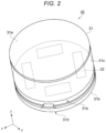
- FIG. 2 is a diagram for explanation of an example of a device that detects a force.
- FIG. 3 is a block diagram for explanation of an example of a control apparatus.
- FIG. 4 is a functional block diagram for explanation of the control apparatus.
- FIG. 5 is a diagram for explanation of an example of determination of one-degree-of-freedom limitation using a vector.
- FIG. 6 is a diagram for explanation of an example of determination of one-degree-of-freedom limitation using a ratio of force components.
- FIG. 7 is a diagram for explanation of an example of determination of two-degree-of-freedom limitation using vectors.
- FIG. 8 is a diagram for explanation of an example of determination of two-degree-of-freedom limitation using a ratio of force components.
- FIG. 9 is a flowchart for determination of a movement limitation direction.
- FIG. 10 is a flowchart for determination of the movement limitation direction.
- FIG. 11 is a perspective view for explanation of a schematic configuration of another embodiment of the robot system.
- FIG. 12 is a flowchart for determination of the movement limitation direction in the other embodiment.
- FIG. 13 is a flowchart for determination of the movement limitation direction in the other embodiment.
- a robot system 100 includes e.g. a robot 1 , a control apparatus 40 , and a teaching apparatus 45 .
- the robot 1 includes a manipulator 10 , a base 11 supporting the manipulator 10 , an end effector 20 , and a force detector 30 .
- a general-purpose robot that can perform various kinds of work by teaching of the teaching apparatus 45 may be employed.
- the manipulator 10 is a robotic arm having e.g. pluralities of mutually coupled links and joints and moving at a plurality of degrees of freedom.
- the manipulator 10 is a six-axis arm having six joints J 1 to J 6 .
- the joints J 2 , J 3 , J 5 are bending joints and the joints J 1 , J 4 , J 6 are twisting joints.
- the end effector 20 is a tool such as e.g. a screw driver, gripper, or grinder.
- the end effector 20 performs various kinds of work including e.g. screwing, gripping, and machining.
- the end effector 20 is attached to the joint J 6 via a mechanical interface in the distal end portion of the manipulator 10 .
- the manipulator 10 is driven by the control apparatus 40 , and thereby, determines a position and a posture of the end effector 20 .
- a tool center point (TCP) as a reference for the position of the end effector 20 is set in a predetermined position near the distal end, for example.
- the TCP can be arbitrarily set and, for example, is set on a rotation axis of the joint J 6 .
- the center of the gripper can be set as the TCP.
- the manipulator 10 has six degrees of freedom as an example.
- the manipulator 10 may have any joint mechanism as long as the robot can realize motion of the TCP at three or more degrees of freedom.
- the base 11 positions the first link of the manipulator 10 , i.e., the single link closest to the base 11 .
- the force detector 30 is a force sensor that detects an external force acting on the manipulator 10 on three detection axes orthogonal to one another via e.g. the end effector 20 . More specifically, the force detector 30 measures forces along the three detection axes and torque around the three detection axes acting on the TCP in a force detector coordinate system as an intrinsic three-dimensional orthogonal coordinate system. In the example shown in FIG. 1 , the force detector 30 is attached to the distal end of the manipulator 10 , however, may be attached to another location of the robot 1 .
- the force detector 30 has a case 31 , a substrate housing member 31 e coupled to the case 31 , a coupling member 31 d coupled to the substrate housing member 31 e , and one or more sensor devices 32 housed within the case 31 .
- the case 31 has a circular columnar shape formed by e.g. a circular first attachment surface 31 a as a top surface, a circular second attachment surface 31 b as a bottom surface, and a cylindrical side wall portion 31 c coupling the top surface and the bottom surface. These may take an integrated structure.
- the second attachment surface 31 b is attached to the distal end of the manipulator 10 and the end effector 20 is attached to the first attachment surface 31 a .
- the shape of the force sensor is not limited, but may be a rectangular parallelepiped shape or a polygonal columnar shape.
- Constituent materials of the first attachment surface 31 a , the second attachment surface 31 b , the cylindrical side wall portion 31 c , and the coupling member 31 d are not particularly limited to, but include e.g. metal materials such as aluminum and stainless steel and ceramics. Further, all of these may be formed using the same or same kind of material or using different materials from one another.
- the sensor device 32 detects translational force components in directions along the respective three detection axes of an x-axis, a y-axis, and a z-axis and moment (torque) of forces around the three detection axes using one or more elements.
- the sensor device 32 is of e.g. a quartz crystal piezoelectric type.
- the quartz crystal piezoelectric type is employed, and thereby, the force detector 30 having good properties in high sensitivity, wide dynamic range, high rigidity, etc. is realized.
- the xyz coordinate system shown in FIG. 1 is a world coordinate system set with respect to the floor surface on which the robot 1 is placed.
- the world coordinate system is a three-dimensional orthogonal coordinate system defined by an x-axis and a y-axis orthogonal to each other along a horizontal plane and a z-axis in a vertically upward direction as a positive direction.
- the negative direction on the z-axis substantially coincides with the direction of the gravity force.
- the rotation angle about the x-axis is expressed by Rx
- the rotation angle about the y-axis is expressed by Ry
- the rotation angle about the z-axis is expressed by Rz.
- Positions and postures of the end effector 20 , the manipulator 10 , the base 11 , etc. may be defined in the world coordinate system.
- position may refer to a pose, i.e., a position and a posture.
- force may refer to a load, i.e., a force and torque.
- the control apparatus 40 controls the position of the TCP in the world coordinate system by driving the manipulator 10 .
- the control apparatus 40 detects a direction of an external force acting on the manipulator 10 using e.g. the force detector 30 , and limits the motion of the TCP according to the external force to one degree of freedom based on the direction of the external force. For example, when an external force along the x-axis of the world coordinate system acts on the TCP by a human, the control apparatus 40 controls the manipulator 10 to move the TCP along only the x-axis of the world coordinate system.
- the control apparatus 40 may limit the motion of the TCP according to the external force to two degrees of freedom based on the direction of the external force. For example, when an external force along an x-y plane parallel to the x-axis and the y-axis of the world coordinate system acts on the TCP by a human, the control apparatus 40 controls the manipulator 10 to move the TCP along the x-y plane. Or, the control apparatus 40 may control the manipulator 10 to change only the posture, but not to change the position of the TCP.
- the control apparatus 40 includes a processor 40 a and a memory 40 b forming a computer system.
- the control apparatus 40 can be formed by e.g. a general-purpose computer.
- the processor 40 a controls the robot 1 by executing a command according to a control program.
- the processor 40 a has a processing circuit such as e.g. a central processing unit (CPU).
- the memory 40 b is a computer-readable storage medium that stores programs and various kinds of data necessary for the control of the robot 1 .
- the memory 40 b is e.g. a random access memory (RAM), a read only memory (ROM), or the like. Part or all of the component elements of the control apparatus 40 may be placed inside of the housing of the robot 1 .
- the control apparatus 40 respectively communicates with the robot 1 and the teaching apparatus 45 via communication links.
- the communication links may be wired or wireless or combinations of wired and wireless connections.
- the control apparatus 40 may control the end effector 20 .
- the control apparatus 40 may grip an object by driving the end effector 20 .
- the control apparatus 40 acquires a force applied to the TCP based on the value acquired by the force detector 30 .
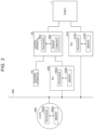
- the control apparatus 40 may include a plurality of processors. That is, in the example shown in FIG. 3 , the control apparatus 40 can configure a control apparatus that controls the robot 1 with personal computers (PCs) 400 , 410 connected to the control apparatus 40 via a network 450 and a cloud 500 as a service server.
- the PC 400 includes a processor 400 a and a memory 400 b and the PC 410 includes a processor 410 a and a memory 410 b .
- the cloud 500 includes a processor 500 a and a memory 500 b .
- the control apparatus 40 may realize a control apparatus that controls the robot 1 using hardware resources of the other devices including the processors 400 a , 410 a , 500 a and the memories 400 b , 410 b , 500 b.
- the teaching apparatus 45 is a computer that teaches programs to the robot 1 via the control apparatus 40 .
- the teaching apparatus 45 may be a dedicated computer such as a teaching pendant or a general-purpose computer in which programs for teaching the robot 1 are installed.
- the teaching apparatus 45 may include a housing separate from that of the control apparatus 40 or share a hardware resource with the control apparatus 40 .
- the joints J 1 to J 6 of the manipulator 10 have motors M 1 to M 6 as actuators and encoders E 1 to E 6 as angle sensors, respectively.
- the motors M 1 to M 6 are respectively driven under the control by the control apparatus 40 and rotate the joints J 1 to J 6 , respectively.
- the encoders E 1 to E 6 detect the rotation angles of the motors M 1 to M 6 and output the angles to the control apparatus 40 .
- the control apparatus 40 has a force control unit 41 , a position control unit 42 , and a command integration unit 43 as a logical structure.
- the force control unit 41 , the position control unit 42 , and the command integration unit 43 are realized by the control apparatus 40 executing a preinstalled control program.
- the force control unit 41 , the position control unit 42 , and the command integration unit 43 may be respectively formed by pluralities of processing circuits or formed by an integrated processing circuit to one another.
- the control apparatus 40 has a first conversion unit U 1 that bi-directionally converts between a combination of the respective rotation angles of the motors M 1 to M 6 and a position of the TCP in the world coordinate system based on a prestored correspondence relationship.
- the first conversion unit U 1 converts a position S in the world coordinate system into respective rotation angles Da of the motors M 1 to M 6 .
- the position S may represent a position and a posture on the six axes (x, y, z, Rx, Ry, Rz) defining the world coordinate system.
- the control signals output by the control apparatus 40 to the motors M 1 to M 6 are e.g. pulse-width modulated (PWM) signals.
- PWM pulse-width modulated
- the control apparatus 40 has a second conversion unit U 2 that converts a signal detected by the force detector 30 into a force f Sp in the world coordinate system based on the correspondence relationship showing the posture of the sensor coordinate system with respect to each position S of the TCP in the world coordinate system.
- the second conversion unit U 2 may calculate a torque component of the force f Sp from a force component of the force f Sp and a distance from the TCP to the force detector 30 .
- the force control unit 41 has a target force calculation part 41 a , a force detection part 41 b , a movement limitation determination part 41 c , and a force control correction amount calculation part 41 d as a logical structure.
- the force control unit 41 has a function for controlling an external force f S acting on the TCP to be a predetermined target force f St .
- the force control unit 41 calculates a force control correction amount ⁇ S for correction of the target position to set the external force f S to the target force f St along a movement limitation command L 1 and outputs the amount to the command integration unit 43 .
- the target force calculation part 41 a calculates the target force f St based on e.g. a command C 1 stored by the control apparatus 40 according to the teaching by the teaching apparatus 45 . In a case of direct teaching, the target force calculation part 41 a calculates the target force f St for execution of profile control to set the force applied to the TCP of the manipulator 10 to zero so that the worker may grip the end effector 20 attached to the distal end of the manipulator 10 and apply a force to the end effector 20 .
- the force detection part 41 b acquires the external force f S acting on the TCP on the three detection axes orthogonal to one another by the force detector 30 . Specifically, the force detection part 41 b detects the external force f S acting on the TCP without an influence of the gravity force by providing gravity compensation to remove a component due to the gravity force to the force f Sp acquired from the force detector 30 via the second conversion unit U 2 . The three detection axes of the force detection part 41 b can be converted to the three detection axes of the force detector 30 to each other via the second conversion unit U 2 .
- the external force f S acting on the TCP with reference to the detection axes of the force detector 30 and the external force f S acting on the TCP with reference to the detection axes of the force detection part 41 b may be treated the same as each other.
- the force detection part 41 b can designate any coordinate system of the world coordinate system, the tool coordinate system, the local coordinate system, etc. as the detection axes of the force detector 30 .
- the movement limitation determination part 41 c limits the degree of freedom of the motion according to the external force f S on the distal end of the manipulator 10 based on the direction of the external force f S detected by the force detection part 41 b .
- the distal end of the manipulator 10 strictly refers to the TCP.
- the movement limitation determination part 41 c generates the movement limitation command L 1 for limiting the motion of the TCP according to the external force f S to one degree of freedom when the external force f S satisfies a first condition.
- the first condition is a condition for determination as to whether or not the motion of the TCP according to the external force f S has one degree of freedom.
- the first condition is that an angle formed by a directional vector of the external force f S and the detection axis having the maximum component of the external force f S of the three detection axes of the force detector 30 is smaller than a first value ⁇ th .
- the world coordinate system is designated as the coordinate system as reference of motion by a command C 2 stored by the control apparatus 40 according to teaching by the teaching apparatus 45 .
- the detection axis having the maximum external force f S component in the world coordinate system is the x-axis and a unit vector of the x-axis is a vector v 1 .
- the movement limitation determination part 41 c limits the motion direction of the TCP according to the external force f S to only the x-axis direction of the world coordinate system when an angle formed by the external force f S and the x-axis is smaller than the first value ⁇ th .
- the first value ⁇ th may be set to an arbitrary value from 0 [deg] to 180 [deg] using the teaching apparatus 45 .
- the coordinate system designated by the command C 2 the tool coordinate system or the local coordinate system can be employed.
- the movement limitation determination part 41 c may limit the degree of freedom of the motion of the TCP according to the external force f S based on a distribution of the magnitude of the respective components of the external force f S on the three detection axes of the force detector 30 .
- the largest value of the respective components of the external force f S is x 1 [N] and the second largest value is y 1 [N].
- the movement limitation determination part 41 c limits the motion direction of the TCP according to the external force f S to the x-axis direction when the external force f S satisfies (x 1 /y 1 )>k 1 .
- the movement limitation determination part 41 c may generate the movement limitation command L 1 for limiting the motion of the TCP according to the external force f S to two degrees of freedom when the external force f S satisfies a second condition.
- the second condition is a condition for determination as to whether or not the motion of the TCP according to the external force f S has two degrees of freedom.
- the second condition is that an angle formed by an outer product of the directional vector of the external force f S and a unit vector of the detection axis having the maximum component of the external force f S of the three detection axes of the force detector 30 and a unit vector of the detection axis having the minimum component of the external force f S of the three detection axes is smaller than a second value ⁇ th .
- the detection axis having the maximum external force f S component in the world coordinate system is the x-axis and the unit vector of the x-axis is the vector v 1 .
- the detection axis having the minimum external force f S component is the z-axis and a unit vector of the z-axis is a vector v 2 .
- the movement limitation determination part 41 c limits the motion direction of the TCP according to the external force f S to a direction along the x-y plane of the world coordinate system when an angle formed by the vector v 3 and the vector v 2 is smaller than the second value ⁇ th .
- the second value ⁇ th may be set to an arbitrary value from 0 [deg] to 180 [deg] using the teaching apparatus 45 .
- the second value ⁇ th may be the same value as the first value ⁇ th or a different value.
- a condition that the largest value of the magnitude of the respective components of the external force f S on the three detection axes of the force detector 30 is smaller than a product of the second largest value and a second constant k 2 and the second largest value is larger than a product of the smallest value and a third constant k 3 may be employed.
- a calculation using vectors is unnecessary.
- the largest value of the respective components of the external force f S is x 2 [N]
- the second largest value is y 2 [N]
- the smallest value is z 2 [N].
- the movement limitation determination part 41 c limits the motion direction of the TCP according to the external force f S to the direction along the x-y plane when the external force f S satisfies (x 2 /y 2 ) c k 2 and (y 2 /z 2 )>k 3 at the same time.
- Other motion of the TCP limited to one degree of freedom by the movement limitation command L 1 includes translational motion in the directions along the respective axes of y, z and rotational motion around the respective axes of x, y, z.
- Other motion of the TCP limited to two degrees of freedom by the movement limitation command L 1 includes motion along the y-z plane and motion along the x-z plane.
- the motion of the TCP limited by the movement limitation command L 1 includes motion to change only the posture, motion to freely change the position and the posture, etc.
- the limitation of the motion of the TCP is changed by a combination of the command C 2 and the movement limitation command L 1 .
- the movement limitation determination part 41 c generates and outputs the movement limitation command L 1 when the external force f S detected by the force detection part 41 b is larger than a predetermined threshold value.
- the movement limitation determination part 41 c continues output of the same movement limitation command L 1 until the external force f S is equal to or smaller than the threshold value.
- the force control correction amount calculation part 41 d calculates the force control correction amount ⁇ S for correction of a target position S t to set the external force f S to the target force f St from the target force f St , the external force f S , and the movement limitation command L 1 .
- the force control correction amount ⁇ S refers to an amount in which the TCP should move from the position S to resolve a force deviation ⁇ f S of the external force f S from the target force f St when the TCP is subjected to mechanical impedance.
- the force control correction amount calculation part 41 d calculates the force control correction amount ⁇ S by e.g. active impedance control that realizes virtual mechanical impedance using the motors M 1 to M 6 . For example, when the motion of the TCP is limited to the direction along the x-axis of the world coordinate system by the movement limitation command L 1 , other values than the x-axis component of ⁇ S are zero.
- the position control unit 42 calculates the target position Si of the TCP in the world coordinate system.
- the position control unit 42 calculates the present position of the TCP without change as the target position S t when direct teaching is performed in the robot system 100 .
- the position control unit 42 may calculate the target position S t of the TCP using the control program generated by the teaching apparatus 45 , the output of the sensor that detects the position of the object, or the like.
- the command integration unit 43 has a feedback control part 43 a and a force control correction amount addition part 43 b as a logical structure.
- the command integration unit 43 integrates the target position St as a control command calculated by the position control unit 42 and the force control correction amount ⁇ S as a control command calculated by the force control unit 41 .
- the command integration unit 43 outputs an operation amount to the robot 1 for achievement of a target value according to the integrated control command.
- the force control correction amount addition part 43 b adds the force control correction amount ⁇ S to the target position St.
- the force control correction amount addition part 43 b calculates a commanded position S tt applied to the motors M 1 to M 6 of the manipulator 10 .
- the commanded position S tt refers to a final target value of the TCP in the world coordinate system.
- the first conversion unit U 1 converts the commanded position S tt in the world coordinate system into target angles Di as target values of the respective rotation angles of the motors M 1 to M 6 .
- the feedback control part 43 a performs feedback control to control to the target angles D t using real rotation angles D a of the motors M 1 to M 6 as control amounts.
- the feedback control part 43 a acquires the rotation angles D a from output of the encoders E 1 to E 6 .
- the feedback control part 43 a calculates operation amounts D e from the control amounts D a and the target angles D t to control the motors M 1 to M 6 .
- control apparatus 40 Referring to flowcharts in FIGS. 9 and 10 , an example of processing of the control apparatus 40 will be explained as a control method for the robot 1 in the robot system 100 .
- a command to start direct teaching is input from the teaching apparatus 45 , and the control apparatus 40 moves to a direct teaching mode and starts direct teaching.
- the command to start direct teaching may be input to the control apparatus 40 from another than the teaching apparatus 45 .
- the command to start direct teaching may be input to the control apparatus 40 , for example, when a switch attached to the robot 1 is pressed.
- the movement limitation determination part 41 c acquires the external force f S and torque of the external force f S detected by the force detection part 41 b as external force information. That is, the external force information includes the forces along the three detection axes and the torque around the three detection axes of the force detection part 41 b.
- the movement limitation determination part 41 c determines whether or not magnitude of the torque of the external force f S acquired at step S 42 is larger than a predetermined threshold value. When the magnitude of the torque is larger than the threshold value, the movement limitation determination part 41 c moves processing to step S 44 and, when the magnitude of the torque is equal to or smaller than the threshold value, moves processing to step S 52 .
- the movement limitation determination part 41 c determines whether or not the largest value of the magnitude of the torque of the respective components of the external force f S acquired at step S 42 is larger than a value obtained by multiplication of the second largest value by a constant. When the maximum value is larger than the value obtained by multiplication by the constant, the movement limitation determination part 41 c moves the processing to step S 45 and, when the maximum value is equal to or smaller than the value obtained by multiplication by the constant, moves the processing to step S 47 .
- the movement limitation determination part 41 c generates the movement limitation command L 1 to limit the motion of the TCP around the detection axis having the maximum value of the magnitude of the torque of the respective components of the external force f S acquired at step S 42 and outputs the command to the force control correction amount calculation part 41 d .
- the movement limitation determination part 41 c limits the motion of the TCP to one degree of freedom only around the x-axis.
- the movement limitation determination part 41 c determines whether or not the external force f S detected in the force detection part 41 b is smaller than a predetermined threshold value. When the external force f S is smaller than the threshold value, the movement limitation determination part 41 c determines that the external force f S acting on the robot 1 is reduced and stops output of the movement limitation command L 1 generated at step S 45 , and moves the processing to step S 61 . When the external force f S is equal to or larger than the threshold value, the movement limitation determination part 41 c repeats the processing at step S 45 .
- the movement limitation determination part 41 c determines whether or not the external force f S acquired at step S 42 is equal to or larger than a predetermined threshold value. When the external force f S is equal to or larger than the threshold value, the movement limitation determination part 41 c moves the processing to step S 48 and, when the external force f S is smaller than the threshold value, moves the processing to step S 50 .
- the movement limitation determination part 41 c generates the movement limitation command L 1 to allow motion of the TCP at six degrees of freedom and outputs the command to the force control correction amount calculation part 41 d . That is, in this case, the movement limitation determination part 41 c does not limit the motion of the TCP according to the external force f S .
- the movement limitation determination part 41 c determines whether or not the external force f S detected in the force detection part 41 b is smaller than a predetermined threshold value. When the external force f S is smaller than the threshold value, the movement limitation determination part 41 c determines that the external force f S acting on the robot 1 is reduced and stops output of the movement limitation command L 1 generated at step S 48 , and moves the processing to step S 61 . When the external force f S is equal to or larger than the threshold value, the movement limitation determination part 41 c repeats the processing at step S 48 .
- the movement limitation determination part 41 c generates the movement limitation command L 1 to limit the motion of the TCP at three degrees of freedom of only the posture and outputs the command to the force control correction amount calculation part 41 d . That is, the movement limitation determination part 41 c allows the motion of the TCP to change the posture around the three detection axes and disallows motion to change the position along the three detection axes.
- the movement limitation determination part 41 c determines whether or not the external force f S detected in the force detection part 41 b is smaller than a predetermined threshold value. When the external force f S is smaller than the threshold value, the movement limitation determination part 41 c determines that the external force f S acting on the robot 1 is reduced and stops output of the movement limitation command L 1 generated at step S 50 , and moves the processing to step S 61 . When the external force f S is equal to or larger than the threshold value, the movement limitation determination part 41 c repeats the processing at step S 50 .
- the movement limitation determination part 41 c determines whether or not the external force f S acquired at step S 42 is equal to or larger than a predetermined threshold value. When the external force f S is equal to or larger than the threshold value, the movement limitation determination part 41 c moves the processing to step S 53 and, when the external force f S is smaller than the threshold value, returns the processing to step S 42 .
- the movement limitation determination part 41 c determines whether or not the external force f S acquired at step S 42 satisfies the first condition.
- the movement limitation determination part 41 c moves the processing to step S 54 and, when the external force f S does not satisfy the first condition, moves the processing to step S 56 .
- the first condition is a condition for determination as to whether or not the motion of the TCP according to the external force f S is limited to one degree of freedom.
- the movement limitation determination part 41 c generates the movement limitation command L 1 to limit the motion of the TCP according to the external force f S to one degree of freedom around the detection axis having the largest component of the external force f S and outputs the command to the force control correction amount calculation part 41 d .
- the movement limitation determination part 41 c generates the movement limitation command L 1 to limit the motion of the TCP to one degree of freedom in the x-axis direction.
- the movement limitation determination part 41 c determines whether or not the external force f S detected in the force detection part 41 b is smaller than a predetermined threshold value. When the external force f S is smaller than the threshold value, the movement limitation determination part 41 c determines that the external force f S acting on the robot 1 is reduced and stops output of the movement limitation command L 1 generated at step S 54 , and moves the processing to step S 61 . When the external force f S is equal to or larger than the threshold value, the movement limitation determination part 41 c repeats the processing at step S 54 .
- the movement limitation determination part 41 c determines whether or not the external force f S acquired at step S 42 satisfies the second condition.
- the movement limitation determination part 41 c moves the processing to step S 57 and, when the external force f S does not satisfy the second condition, moves the processing to step S 59 .
- the second condition is a condition for determination as to whether or not the motion of the TCP according to the external force f S is limited to two degrees of freedom.
- the movement limitation determination part 41 c generates the movement limitation command L 1 to limit the motion of the TCP according to the external force f S to two degrees of freedom along a plane defined by the detection axis having the largest component of the external force f S and the detection axis having the second largest component of the external force f S and outputs the command to the force control correction amount calculation part 41 d .
- the movement limitation determination part 41 c generates the movement limitation command L 1 to limit the motion of the TCP to two degrees of freedom along the x-y plane.
- the movement limitation determination part 41 c determines whether or not the external force f S detected in the force detection part 41 b is smaller than a predetermined threshold value. When the external force f S is smaller than the threshold value, the movement limitation determination part 41 c determines that the external force f S acting on the robot 1 is reduced and stops output of the movement limitation command L 1 generated at step S 57 , and moves the processing to step S 61 . When the external force f S is equal to or larger than the threshold value, the movement limitation determination part 41 c repeats the processing at step S 57 .
- the movement limitation determination part 41 c generates the movement limitation command L 1 to limit the motion of the TCP to three degrees of freedom of only the position and outputs the command to the force control correction amount calculation part 41 d . That is, the movement limitation determination part 41 c allows the motion of the TCP to change the position along the three detection axes and disallows motion to change the posture around the three detection axes.
- the movement limitation determination part 41 c determines whether or not the external force f S detected in the force detection part 41 b is smaller than a predetermined threshold value. When the external force f S is smaller than the threshold value, the movement limitation determination part 41 c determines that the external force f S acting on the robot 1 is reduced and stops output of the movement limitation command L 1 generated at step S 59 , and moves the processing to step S 61 . When the external force f S is equal to or larger than the threshold value, the movement limitation determination part 41 c repeats the processing at step S 59 .
- the movement limitation determination part 41 c determines whether or not the direct teaching is ended according to e.g. an operation by the worker on the teaching apparatus 45 .
- the movement limitation determination part 41 c moves the processing to step S 62 and, when the direct teaching is not ended, returns the processing to step S 42 .
- the output of the movement limitation command L 1 is stopped and the TCP is not moving. That is, only the position control on the TCP is executed by the control apparatus 40 .
- step S 62 for example, a command to end the direct teaching is input from the teaching apparatus 45 , the control apparatus 40 ends the direct teaching mode and the direct teaching is ended.
- the plurality of constants used for the series of processing shown in FIGS. 9 and 10 may be arbitrarily set. Therefore, the constants may be set to the same value as one another or set to different values from one another. The same applies to the plurality of threshold values.
- the movement limitation command L 1 is automatically generated by the movement limitation determination part 41 c based on the external force f S acting on the end effector 20 .
- an operation by the worker of setting the limitation of the motion of the TCP using the teaching apparatus 45 is unnecessary and the time required for direct teaching is shortened.
- a program for moving the TCP with limitation on the x-y plane and subsequently moving the TCP along the x-axis is not generated unless the degree of freedom to be limited is selected by the worker using a GUI of the teaching apparatus or the like.
- the robot system 100 the external force f S applied to the end effector 20 is changed, and thereby, the degree of freedom of the motion of the TCP is automatically limited.
- work in the direct teaching may be simplified.
- the robot 1 is not limited to the robot including the single manipulator 10 as the six-axis arm.
- the numbers of manipulators and end effectors of the robot 1 , the degree of freedom of the manipulator, etc. may be arbitrarily changed.
- the robot 1 may be a Cartesian robot, a horizontal articulated robot, a vertical articulated robot, a dual-arm robot, or the like.
- the position of the force detector 30 is not limited to the distal end of the manipulator 10 .
- a robot system 101 includes a robot 2 , the control apparatus 40 , and the teaching apparatus 45 .
- the robot 2 is a horizontal articulated robot including a base 21 , a manipulator 22 , the end effector 20 , and a force detector 300 .
- the force detector 300 has e.g. a rectangular parallelepiped shape and is attached to a lower part of the base 21 .
- the manipulator 22 is an arm having a first link 221 and a second link 222 .
- the manipulator 22 includes four joints J 1 to J 4 respectively having axes along the z-axis of the world coordinate system.
- the three joints J 1 , J 2 , J 4 are rotary joints and the joint J 3 is a translatory joint. That is, a TCP corresponding to the distal end of the manipulator 22 has four degrees of freedom.
- the robot 2 may further include a force detector that detects an external force f S acting on the manipulator 22 on the distal end of the manipulator 22 like the force detector 30 of the robot 1 .
- the configuration of the functional block of the robot system 101 is substantially the same as a configuration obtained by removal of the joints J 5 , J 6 from the block diagram in FIG. 4 , and the overlapping explanation will be omitted.
- steps S 71 to S 76 , S 77 , S 78 , S 79 , S 80 to S 89 in the flowcharts in FIGS. 12 and 13 correspond to steps S 41 to S 46 , S 52 , S 48 , S 49 , S 53 to S 62 in the flowcharts in FIGS. 9 and 10 , respectively. That is, the flowcharts in FIGS. 12 and 13 are formed by removal of the steps S 47 , S 50 , S 51 from the flowcharts in FIGS. 9 and 10 . Accordingly, the detailed explanation of the respective steps in the flowcharts in FIGS. 12 and 13 will be omitted.
- the movement limitation determination part 41 c determines whether or not the largest value of the magnitude of the torque of the respective components of the external force f S acquired at step S 72 is larger than a value obtained by multiplication of the second largest value by a constant. It is considered that the torque of the external force f S acting on the TCP is mainly torque around the z-axis in the world coordinate system. Accordingly, the movement limitation command L 1 generated at step S 75 is a command to limit the TCP to one degree of freedom around the z-axis. On the other hand, at step S 78 , the movement limitation determination part 41 c allows the motion of the TCP at the four degrees of freedom and does not limit the motion of the TCP according to the external force f S .
- a first condition and a second condition at the steps S 80 and S 83 are the same as those of the above described embodiment.
- the motion of the TCP is limited to one degree of freedom along the x-axis of the world coordinate system. That is, the TCP translationally moves along the x-axis in the world coordinate system according to the external force f S .
- the present disclosure includes other various embodiments not described above such as configurations obtained by mutual application of the above described respective configurations to one another.
- the technical scope of the present disclosure is defined only by the matters specifying the invention that relates to claims appropriate from the above description.
Landscapes
- Engineering & Computer Science (AREA)
- Robotics (AREA)
- Mechanical Engineering (AREA)
- Automation & Control Theory (AREA)
- Manipulator (AREA)
- Numerical Control (AREA)
Abstract
Description
Claims (3)
Applications Claiming Priority (2)
| Application Number | Priority Date | Filing Date | Title |
|---|---|---|---|
| JP2020047310A JP7528479B2 (en) | 2020-03-18 | 2020-03-18 | Robot control method and robot system |
| JP2020-047310 | 2020-03-18 |
Publications (2)
| Publication Number | Publication Date |
|---|---|
| US20210291365A1 US20210291365A1 (en) | 2021-09-23 |
| US12128564B2 true US12128564B2 (en) | 2024-10-29 |
Family
ID=77747367
Family Applications (1)
| Application Number | Title | Priority Date | Filing Date |
|---|---|---|---|
| US17/203,773 Active 2041-10-20 US12128564B2 (en) | 2020-03-18 | 2021-03-17 | Control method for robot and robot system |
Country Status (3)
| Country | Link |
|---|---|
| US (1) | US12128564B2 (en) |
| JP (1) | JP7528479B2 (en) |
| CN (1) | CN113492400B (en) |
Families Citing this family (1)
| Publication number | Priority date | Publication date | Assignee | Title |
|---|---|---|---|---|
| US20240359322A1 (en) * | 2021-09-14 | 2024-10-31 | Fanuc Corporation | Robot system and robot control device |
Citations (10)
| Publication number | Priority date | Publication date | Assignee | Title |
|---|---|---|---|---|
| EP2131257A1 (en) * | 2008-06-06 | 2009-12-09 | KUKA Roboter GmbH | Method and device for controlling a manipulator |
| JP2012157946A (en) | 2011-02-01 | 2012-08-23 | Fanuc Ltd | Robot teaching device for performing direct teaching of robot based on output of force sensor |
| US20150081098A1 (en) * | 2013-09-19 | 2015-03-19 | Kuka Laboratories Gmbh | Method For Manually Adjusting The Pose Of A Manipulator Arm Of An Industrial Robot And Industrial Robots |
| US20160288332A1 (en) * | 2015-03-30 | 2016-10-06 | Seiko Epson Corporation | Robot, robot control apparatus and robot system |
| JP2017074669A (en) | 2015-10-14 | 2017-04-20 | 株式会社リコー | Manipulator control device, manipulator drive device, and robot system |
| JP2017094440A (en) | 2015-11-24 | 2017-06-01 | 川崎重工業株式会社 | Direct teaching method of robot |
| US20170266815A1 (en) | 2016-03-18 | 2017-09-21 | Seiko Epson Corporation | Control device, robot, and robot system |
| US20180200880A1 (en) * | 2015-07-14 | 2018-07-19 | Kuka Roboter Gmbh | Ascertaining An Input Command For A Robot, Said Input Command Being Entered By Manually Exerting A Force Onto The Robot |
| US20190217480A1 (en) * | 2016-06-17 | 2019-07-18 | Neuromeka | Controller for end portion control of multi-degree-of-freedom robot, method for controlling multi-degree-of-freedom robot by using controller, and robot operated thereby |
| US20190366549A1 (en) | 2018-05-31 | 2019-12-05 | Seiko Epson Corporation | Control apparatus, robot system and control method |
Family Cites Families (5)
| Publication number | Priority date | Publication date | Assignee | Title |
|---|---|---|---|---|
| JPH06250728A (en) * | 1993-02-26 | 1994-09-09 | Hitachi Constr Mach Co Ltd | Direct teaching device for robot |
| JP4896276B2 (en) * | 2010-01-04 | 2012-03-14 | パナソニック株式会社 | ROBOT, ROBOT CONTROL DEVICE, CONTROL METHOD, AND CONTROL PROGRAM |
| JP6582483B2 (en) * | 2015-03-26 | 2019-10-02 | セイコーエプソン株式会社 | Robot control device and robot system |
| JP6648469B2 (en) * | 2015-10-07 | 2020-02-14 | セイコーエプソン株式会社 | Robot system and robot controller |
| CN105583824B (en) * | 2016-01-26 | 2017-05-24 | 清华大学 | Force control traction and swinging multi-degree-of-freedom mechanical arm control device and method |
-
2020
- 2020-03-18 JP JP2020047310A patent/JP7528479B2/en active Active
-
2021
- 2021-03-16 CN CN202110281885.7A patent/CN113492400B/en active Active
- 2021-03-17 US US17/203,773 patent/US12128564B2/en active Active
Patent Citations (13)
| Publication number | Priority date | Publication date | Assignee | Title |
|---|---|---|---|---|
| EP2131257A1 (en) * | 2008-06-06 | 2009-12-09 | KUKA Roboter GmbH | Method and device for controlling a manipulator |
| JP2012157946A (en) | 2011-02-01 | 2012-08-23 | Fanuc Ltd | Robot teaching device for performing direct teaching of robot based on output of force sensor |
| US20150081098A1 (en) * | 2013-09-19 | 2015-03-19 | Kuka Laboratories Gmbh | Method For Manually Adjusting The Pose Of A Manipulator Arm Of An Industrial Robot And Industrial Robots |
| US20160288332A1 (en) * | 2015-03-30 | 2016-10-06 | Seiko Epson Corporation | Robot, robot control apparatus and robot system |
| US20180200880A1 (en) * | 2015-07-14 | 2018-07-19 | Kuka Roboter Gmbh | Ascertaining An Input Command For A Robot, Said Input Command Being Entered By Manually Exerting A Force Onto The Robot |
| JP2017074669A (en) | 2015-10-14 | 2017-04-20 | 株式会社リコー | Manipulator control device, manipulator drive device, and robot system |
| US20180345492A1 (en) | 2015-11-24 | 2018-12-06 | Kawasaki Jukogyo Kabushiki Kaisha | Direct teaching method of robot |
| JP2017094440A (en) | 2015-11-24 | 2017-06-01 | 川崎重工業株式会社 | Direct teaching method of robot |
| JP2017164876A (en) | 2016-03-18 | 2017-09-21 | セイコーエプソン株式会社 | Control device, robot, and robot system |
| US20170266815A1 (en) | 2016-03-18 | 2017-09-21 | Seiko Epson Corporation | Control device, robot, and robot system |
| US20190217480A1 (en) * | 2016-06-17 | 2019-07-18 | Neuromeka | Controller for end portion control of multi-degree-of-freedom robot, method for controlling multi-degree-of-freedom robot by using controller, and robot operated thereby |
| US20190366549A1 (en) | 2018-05-31 | 2019-12-05 | Seiko Epson Corporation | Control apparatus, robot system and control method |
| JP2019209386A (en) | 2018-05-31 | 2019-12-12 | セイコーエプソン株式会社 | Control device and robot system |
Also Published As
| Publication number | Publication date |
|---|---|
| JP7528479B2 (en) | 2024-08-06 |
| CN113492400B (en) | 2023-12-22 |
| CN113492400A (en) | 2021-10-12 |
| US20210291365A1 (en) | 2021-09-23 |
| JP2021146431A (en) | 2021-09-27 |
Similar Documents
| Publication | Publication Date | Title |
|---|---|---|
| US10434646B2 (en) | Robot control apparatus, robot, and robot system | |
| US11465288B2 (en) | Method of controlling robot | |
| US11090814B2 (en) | Robot control method | |
| US10589424B2 (en) | Robot control device, robot, and robot system | |
| US10864632B2 (en) | Direct teaching method of robot | |
| CN107363830B (en) | Robot control device, robot, and robot system | |
| US10751874B2 (en) | Method of teaching robot and robotic arm control device | |
| KR102867186B1 (en) | Arm and body adjustments | |
| US20180194009A1 (en) | Robot control device and robotic system | |
| US11691290B2 (en) | Robot control method and robot system | |
| JP6661925B2 (en) | Control devices, robots and robot systems | |
| CN113276088B (en) | Teaching methods and robot systems | |
| CN110640748A (en) | Coordinated control method of dual-arm robot based on binocular vision | |
| US20180154520A1 (en) | Control device, robot, and robot system | |
| US12128564B2 (en) | Control method for robot and robot system | |
| JP2016221653A (en) | Robot control device and robot system | |
| JP6668629B2 (en) | Robot controller and robot system | |
| CN114367958A (en) | Adjustment method of force control parameters | |
| WO2018088199A1 (en) | Robot control device, robot, robotic system, and robotic control method | |
| US12162168B2 (en) | Method for controlling robot, robot system, and storage medium | |
| JP2020157459A (en) | Control method and robot system | |
| US12109702B2 (en) | Method of adjusting force control parameter, robot system, and force control parameter adjustment program | |
| JP7841231B2 (en) | Method for adjusting operating parameters | |
| US20230001567A1 (en) | Teaching Support Device | |
| CN118613355A (en) | Teleoperated robot control |
Legal Events
| Date | Code | Title | Description |
|---|---|---|---|
| AS | Assignment |
Owner name: SEIKO EPSON CORPORATION, JAPAN Free format text: ASSIGNMENT OF ASSIGNORS INTEREST;ASSIGNORS:ADACHI, HIROKI;TAKEUCHI, KAORU;KINOSHITA, HIROFUMI;REEL/FRAME:055613/0987 Effective date: 20201217 |
|
| FEPP | Fee payment procedure |
Free format text: ENTITY STATUS SET TO UNDISCOUNTED (ORIGINAL EVENT CODE: BIG.); ENTITY STATUS OF PATENT OWNER: LARGE ENTITY |
|
| STPP | Information on status: patent application and granting procedure in general |
Free format text: DOCKETED NEW CASE - READY FOR EXAMINATION |
|
| STPP | Information on status: patent application and granting procedure in general |
Free format text: NON FINAL ACTION MAILED |
|
| STPP | Information on status: patent application and granting procedure in general |
Free format text: FINAL REJECTION MAILED |
|
| STPP | Information on status: patent application and granting procedure in general |
Free format text: DOCKETED NEW CASE - READY FOR EXAMINATION |
|
| STPP | Information on status: patent application and granting procedure in general |
Free format text: NON FINAL ACTION MAILED |
|
| STPP | Information on status: patent application and granting procedure in general |
Free format text: RESPONSE TO NON-FINAL OFFICE ACTION ENTERED AND FORWARDED TO EXAMINER |
|
| STPP | Information on status: patent application and granting procedure in general |
Free format text: FINAL REJECTION MAILED |
|
| STPP | Information on status: patent application and granting procedure in general |
Free format text: DOCKETED NEW CASE - READY FOR EXAMINATION |
|
| STPP | Information on status: patent application and granting procedure in general |
Free format text: NOTICE OF ALLOWANCE MAILED -- APPLICATION RECEIVED IN OFFICE OF PUBLICATIONS |
|
| ZAAB | Notice of allowance mailed |
Free format text: ORIGINAL CODE: MN/=. |
|
| STPP | Information on status: patent application and granting procedure in general |
Free format text: PUBLICATIONS -- ISSUE FEE PAYMENT VERIFIED |
|
| STCF | Information on status: patent grant |
Free format text: PATENTED CASE |