US12123796B2 - Data generation device and data generation system - Google Patents
Data generation device and data generation system Download PDFInfo
- Publication number
- US12123796B2 US12123796B2 US17/052,988 US201917052988A US12123796B2 US 12123796 B2 US12123796 B2 US 12123796B2 US 201917052988 A US201917052988 A US 201917052988A US 12123796 B2 US12123796 B2 US 12123796B2
- Authority
- US
- United States
- Prior art keywords
- data
- reaction force
- result
- data generation
- generation device
- Prior art date
- Legal status (The legal status is an assumption and is not a legal conclusion. Google has not performed a legal analysis and makes no representation as to the accuracy of the status listed.)
- Active, expires
Links
Images


Classifications
-
- H—ELECTRICITY
- H02—GENERATION; CONVERSION OR DISTRIBUTION OF ELECTRIC POWER
- H02P—CONTROL OR REGULATION OF ELECTRIC MOTORS, ELECTRIC GENERATORS OR DYNAMO-ELECTRIC CONVERTERS; CONTROLLING TRANSFORMERS, REACTORS OR CHOKE COILS
- H02P23/00—Arrangements or methods for the control of AC motors characterised by a control method other than vector control
- H02P23/14—Estimation or adaptation of motor parameters, e.g. rotor time constant, flux, speed, current or voltage
-
- G—PHYSICS
- G01—MEASURING; TESTING
- G01L—MEASURING FORCE, STRESS, TORQUE, WORK, MECHANICAL POWER, MECHANICAL EFFICIENCY, OR FLUID PRESSURE
- G01L3/00—Measuring torque, work, mechanical power, or mechanical efficiency, in general
- G01L3/02—Rotary-transmission dynamometers
- G01L3/04—Rotary-transmission dynamometers wherein the torque-transmitting element comprises a torsionally-flexible shaft
-
- G—PHYSICS
- G01—MEASURING; TESTING
- G01L—MEASURING FORCE, STRESS, TORQUE, WORK, MECHANICAL POWER, MECHANICAL EFFICIENCY, OR FLUID PRESSURE
- G01L3/00—Measuring torque, work, mechanical power, or mechanical efficiency, in general
- G01L3/24—Devices for determining the value of power, e.g. by measuring and simultaneously multiplying the values of torque and revolutions per unit of time, by multiplying the values of tractive or propulsive force and velocity
-
- G—PHYSICS
- G01—MEASURING; TESTING
- G01L—MEASURING FORCE, STRESS, TORQUE, WORK, MECHANICAL POWER, MECHANICAL EFFICIENCY, OR FLUID PRESSURE
- G01L5/00—Apparatus for, or methods of, measuring force, work, mechanical power, or torque, specially adapted for specific purposes
-
- G—PHYSICS
- G01—MEASURING; TESTING
- G01L—MEASURING FORCE, STRESS, TORQUE, WORK, MECHANICAL POWER, MECHANICAL EFFICIENCY, OR FLUID PRESSURE
- G01L5/00—Apparatus for, or methods of, measuring force, work, mechanical power, or torque, specially adapted for specific purposes
- G01L5/16—Apparatus for, or methods of, measuring force, work, mechanical power, or torque, specially adapted for specific purposes for measuring several components of force
-
- G—PHYSICS
- G01—MEASURING; TESTING
- G01N—INVESTIGATING OR ANALYSING MATERIALS BY DETERMINING THEIR CHEMICAL OR PHYSICAL PROPERTIES
- G01N11/00—Investigating flow properties of materials, e.g. viscosity, plasticity; Analysing materials by determining flow properties
- G01N11/10—Investigating flow properties of materials, e.g. viscosity, plasticity; Analysing materials by determining flow properties by moving a body within the material
- G01N11/14—Investigating flow properties of materials, e.g. viscosity, plasticity; Analysing materials by determining flow properties by moving a body within the material by using rotary bodies, e.g. vane
-
- G—PHYSICS
- G05—CONTROLLING; REGULATING
- G05B—CONTROL OR REGULATING SYSTEMS IN GENERAL; FUNCTIONAL ELEMENTS OF SUCH SYSTEMS; MONITORING OR TESTING ARRANGEMENTS FOR SUCH SYSTEMS OR ELEMENTS
- G05B11/00—Automatic controllers
- G05B11/01—Automatic controllers electric
-
- H—ELECTRICITY
- H02—GENERATION; CONVERSION OR DISTRIBUTION OF ELECTRIC POWER
- H02P—CONTROL OR REGULATION OF ELECTRIC MOTORS, ELECTRIC GENERATORS OR DYNAMO-ELECTRIC CONVERTERS; CONTROLLING TRANSFORMERS, REACTORS OR CHOKE COILS
- H02P29/00—Arrangements for regulating or controlling electric motors, appropriate for both AC and DC motors
Definitions
- the present invention relates to a data generation device and a data generation system.
- an electric motor may drive a rotating shaft of a screw provided in a reaction tank to stir a liquid stored in the reaction tank. Also, a method of detecting reaction torque received by the rotating shaft based on an angular response of the rotating shaft is disclosed in Non-Patent Literature 1.
- a control device for controlling the electric motor installed in a factory or the like needs to proceed to the next process after physical properties of a liquid are sufficiently stable in a stirring process.
- the rotating shaft receives reaction torque from the liquid.
- the control device can determine whether or not the physical properties of the liquid have been sufficiently stable based on data of reaction torque that changes in accordance with the physical properties of the liquid.
- a conventional data generation device generates data of reaction torque received by a rotating shaft based on the output of a strain gauge (a torque sensor) attached to the rotating shaft driven by an electric motor.
- the strain gauge easily deteriorates due to a high temperature, the strain gauge may not be usable depending on an environmental temperature. Also, it may be difficult to attach the strain gauge to the rotating shaft because it is necessary to disassemble the existing equipment so that the strain gauge is attached. In this case, there is a problem that the conventional data generation device cannot generate data of reaction torque and the control device cannot determine whether or not the physical properties of the liquid have been sufficiently stable.
- the above-described problem is not limited to a case in which the data generation device generates the data of the reaction torque received by the rotating shaft in a liquid stirring process, and is a common problem when the data generation device generates data of a reaction force received by a member. That is, the conventional data generation device has a problem that the data of the reaction force received by the member cannot be generated unless the strain gauge is used. Also, because the strain gauge needs to be replaced regularly, there is a problem that an opportunity loss occurs due to stopping of the equipment every time an operator replaces the strain gauge.
- an objective of the present invention is to provide a data generation device and a data generation system capable of generating data of a reaction force received by a member without using a strain gauge.
- One aspect of the present invention is a data generation device including: a parameter generator configured to generate value data based on a signal having a correlation with a driving force and generate velocity data based on a signal representing a response of a member driven by the driving force; and a reaction force data generator configured to generate data of a reaction force received by the member from a predetermined object based on the value data and the velocity data.
- the data generation device can generate data of a reaction force received by a member without using a strain gauge.
- the data generation device is the data generation device further including: a physical property data generator configured to generate physical property data of the object based on the data of the reaction force.
- the data generation device can generate physical property data of an object without using a strain gauge.
- the physical property data generator is configured to generate the physical property data by executing a recursive least squares algorithm based on the velocity data, acceleration data generated based on the signal, position data generated based on the signal, and the data of the reaction force.
- the data generation device can generate physical property data based on a value derived from value data generated by the parameter generator and data of a reaction force.
- the physical property data includes any one of an inertia coefficient, a viscosity coefficient, and an elasticity coefficient related to the object.
- the data generation device can acquire coefficients representing quality of a product such as an inertia coefficient, a viscosity coefficient, and an elasticity coefficient.
- the value data is electric current value data.
- the data generation device can generate data of a reaction force received by a member based on electric current data and velocity data.
- the velocity data is angular velocity data.
- the data generation device can generate data of a reaction force received by a member based on value data and angular velocity data.
- the member is a rotating shaft and the data of the reaction force is data of reaction torque.
- the above-described data generation device includes a storage configured to store any one of internal interference torque related to the driving force, gravity term torque, and a dynamic friction coefficient as a parameter, wherein the reaction force data generator generates the data of the reaction force based on the value data, a parameter read from the storage, and the velocity data.
- the data generation device can generate data of a reaction force using a parameter and value data that can be obtained by a factory operator performing measurement in advance using equipment of an actual factory or the like.
- the above-described data generation device includes a storage configured to store an observer gain of the reaction force data generator, wherein the reaction force data generator derives a first result by multiplying the value data by a torque constant related to the driving force, derives a second result by multiplying the first result by an inertia moment of the member and the observer gain of the reaction force data generator, derives a fourth result by subtracting a third result derived based on the parameter from a result of a sum of the first result and the second result, derives a fifth result by applying a low-pass filter to the fourth result, and derives the data of the reaction force by subtracting the second result from the fifth result.
- the data generation device can derive data of a reaction force based on value data and a parameter using an observer included in the reaction data generator.
- the parameter generator derives the velocity data by integrating values obtained by subtracting load torque received by the driving force from values obtained by multiplying the value data by a torque constant related to the driving force.
- the data generation device can derive velocity data by integrating values obtained by subtracting load torque from values obtained by multiplying value data by a torque constant, it is possible to obtain velocity data without providing a sensor for measuring a velocity of a driving force.
- the data generation device transmits the data of the reaction force to a higher-order control device including a controller configured to execute control based on the data of the reaction force.
- the data generation device can transmit generated data of a reaction force to the higher-order control device, thereby implementing control of a driving force.
- the data generation device can generate data of reaction torque received by a rotating shaft based on value data and velocity data.
- a data generation system including a data generation device for generating data and a higher-order control device, wherein the data generation device includes a parameter generator configured to generate value data based on a signal having a correlation with a driving force and generate velocity data based on a signal representing a response of a member driven by the driving force; a reaction force data generator configured to generate data of a reaction force received by the member from a predetermined object based on the value data and the velocity data; and a first communicator configured to transmit the data of the reaction force and wherein the higher-order control device includes a second communicator configured to receive the data of the reaction force; and a controller configured to execute control based on the received data of the reaction force.
- the data generation device includes a parameter generator configured to generate value data based on a signal having a correlation with a driving force and generate velocity data based on a signal representing a response of a member driven by the driving force; a reaction force data generator configured to generate data of a reaction force received by the member from a pre
- the data generation system can execute control based on data of a reaction force received by a member without using a strain gauge.
- the controller outputs a control signal for stopping the driving force in case that the data of the reaction force converges within a range from a predetermined upper limit to a lower limit.
- the data generation system can end a current process and proceed to the next process in the step in which the acquisition of desired physical property data has been achieved, it is possible to reduce an ineffective operation of continuing the process for a long time.
- the above-described data generation system includes a storage configured to store any one of internal interference torque related to the driving force, gravity term torque, and a dynamic friction coefficient as a parameter, wherein the reaction force data generator generates the data of the reaction force based on the value data, a parameter read from the storage, and the velocity data.
- the data generation system can generate data of a reaction force using a parameter and value data that can be obtained by a factory operator performing measurement in advance using equipment of an actual factory or the like.
- the above-described data generation system includes a storage configured to store an observer gain of the reaction force data generator, wherein the reaction force data generator derives a first result by multiplying the value data by a torque constant related to the driving force, derives a second result by multiplying the first result by an inertia moment of the member and the observer gain of the reaction force data generator, derives a fourth result by subtracting a third result derived based on the parameter from a result of a sum of the first result and the second result, derives a fifth result by applying a low-pass filter to the fourth result, and derives the data of the reaction force by subtracting the second result from the fifth result.
- the data generation system can derive data of a reaction force based on value data and a parameter using an observer included in the reaction data generator.
- the parameter generator derives the velocity data by integrating values obtained by subtracting load torque received by the driving force from values obtained by multiplying the value data by a torque constant related to the driving force.
- the data generation system can derive velocity data by integrating values obtained by subtracting load torque from values obtained by multiplying value data by a torque constant, it is possible to obtain velocity data without providing a sensor for measuring a velocity of a driving force.
- the data generation device further includes a physical property data generator configured to generate physical property data of the object based on the data of the reaction force, the first communicator transmits the physical property data, the second communicator receives the physical property data, and the controller executes control based on the received physical property data.
- the data generation system can execute control based on physical property data of an object without using a strain gauge.
- the controller outputs a control signal for controlling the driving force so that a difference between the received physical property data and predetermined physical property data is reduced.
- the data generation system can adjust quality of a product so that the acquisition of desired physical property data is achieved while the product is being manufactured.
- the physical property data generator generates the physical property data by executing a recursive least squares algorithm based on the velocity data, acceleration data generated based on a signal representing a response of a member driven by the driving force, position data generated based on a signal representing a response of a member driven by the driving force, and the data of the reaction force.
- the physical property data includes any one of an inertia coefficient, a viscosity coefficient, and an elasticity coefficient related to the object.
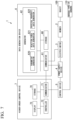
- FIG. 1 is a diagram showing an example of a configuration of a data generation system according to a first embodiment.
- FIG. 2 is a diagram showing an example of a process of generating data of a reaction force according to the first embodiment.
- FIG. 3 is a diagram showing a list of symbols according to the first embodiment.
- FIG. 5 is a diagram showing a second example of a trend graph according to the first embodiment.
- FIG. 6 is a diagram showing an example of an operation of a data generation system according to the first embodiment.
- FIG. 7 is a diagram showing an example of a configuration of a data generation system according to a second embodiment.
- FIG. 9 is a diagram showing an example of an operation of a data generation system according to the second embodiment.
- FIG. 1 is a diagram showing an example of a configuration of a data generation system 1 .
- the data generation system 1 is a system for generating data such as physical quantity data.
- the data generation system 1 is provided in, for example, a plant, a factory, or the like.
- the data generation system 1 includes a member 2 , an electric motor 3 , a power supply device 4 , a control device 5 , a data generation device 6 , and a higher-order control device 7 .
- the member 2 is a member provided in mechanical equipment such as a screw, a pump, a press machine, an injection molding processing machine, a robot arm, a drill system, a polishing machine, a machine tool, or a mounting machine (a mounter), and is, for example, a rotating shaft or a slider.
- the member 2 is driven by an electric motor 3 .
- an angular response (a rotation angle) of the member 2 changes due to driving by the electric motor 3 .
- the member 2 is a slider
- the member 2 moves in a predetermined direction according to driving by the electric motor 3 .
- the member 2 applies a force to an object 100 which is a predetermined object according to driving by the electric motor 3 .
- the object 100 is, for example, a liquid stored in a reaction tank.
- the object 100 is, for example, a printed circuit board.
- the member 2 receives a reaction force from the object 100 .
- the member 2 is a rotating shaft, the rotating member 2 receives reaction torque from the object 100 .
- the electric motor 3 (an actuator) is a device that operates in accordance with electric power supplied from the power supply device 4 .
- the electric motor 3 drives the member 2 in accordance with the supplied power, i.e., an electric current and a voltage.
- the driving force of the electric motor 3 has a correlation with a value representing the electric current supplied to the electric motor 3 (an electric current value I). For example, driving torque (Nm) serving as a driving force is expressed by a result of multiplying the electric current value I (A) by a torque constant K t (Nm/A).
- the electric motor 3 outputs a signal representing a response (hereinafter referred to as a “response signal”) to the data generation device 6 with respect to the response of the member 2 that has received the driving force.
- the response signal is, for example, a signal corresponding to, for example, an angle (rad), an angular velocity (a rotational velocity) (rad/s), and angular acceleration (rad/s 2 ) of the member 2 which rotates.
- the response signal is, for example, a signal corresponding to a position (m), a velocity (m/s), and acceleration (m/s 2 ) of the member 2 which moves.
- the response signal may be a digital signal or an analog signal.
- the electric motor 3 includes an encoder, the electric motor 3 outputs a digital signal corresponding to a position or an angular response of the member 2 as a response signal to the data generation device 6 .
- the electric motor 3 includes a Hall sensor, the electric motor 3 outputs an analog signal (a waveform signal) according to the position or the angular response of the member 2 as the response signal to the data generation device 6 .
- the power supply device 4 is a device that supplies electric power, and is, for example, an inverter, a motor driver, or a three-phase power supply.
- the power supply device 4 acquires, for example, a set value of an electric current, a driving force, or driving torque from the control device 5 .
- the power supply device 4 supplies the electric power represented by the acquired set value to the electric motor 3 .
- the control device 5 is a device that controls the power supply device 4 , and is, for example, a programmable logic controller (PLC).
- the control device 5 acquires a control signal representing an electric current value, a driving timing, or the like from the higher-order control device 7 .
- the control signal is, for example, a signal representing ON or OFF, a signal representing a driving timing, or a signal representing a set value such as an electric current or a velocity.
- the control device 5 outputs a set value such as an electric current or a velocity to the power supply device 4 in accordance with the control signal.
- the control device 5 reads physical quantity data of various types of sensors 110 connected to the control device 5 , for example, a temperature sensor, a pressure sensor, a flow rate sensor, and the like. For example, the control device 5 reads the physical quantity data of the object 100 and transmits the physical quantity data to the communicator 71 .
- the data generation device 6 is an information processing device that generates data.
- the data generation device 6 includes a storage 60 , a communicator 61 , and a generator 62 .
- the storage 60 , the communicator 61 , and the generator 62 are provided in a control device such as a PLC.
- the communicator 61 and the generator 62 are implemented by a processor such as a central processing unit (CPU) executing a program (library).
- This program may be a program of an application that operates on an operating system, for example, a program of an application that operates on a real-time operating system.
- the communicator 61 and the generator 62 may be implemented using hardware such as a large-scale integration (LSI) circuit and an application specific integrated circuit (ASIC).
- the communicator 61 and the generator 62 may be implemented as a hardware module of a control device such as a PLC.
- the storage 60 is a non-volatile storage device (a non-transitory recording medium) such as a flash memory.
- the storage 60 stores programs to be executed by the communicator 61 and the generator 62 .
- the storage 60 may further include a volatile recording medium such as a random-access memory (RAM).
- RAM random-access memory
- the communicator 61 (a first communicator) receives a driving force signal from the power supply device 4 .
- the communicator 61 receives a response signal from the electric motor 3 .
- the communicator 61 records data included in the driving force signal and data included in the response signal in the storage 60 in association with a time. Also, in case that the communicator 61 has received the analog signal, the communicator 61 converts the received analog signal into a digital signal and records the digital signal as a conversion result in the storage 60 .
- the communicator 61 receives a response signal measured with respect to the object 100 from the electric motor 3 via the member 2 .
- the communicator 61 records the response signal measured with respect to the object 100 in the storage 60 in association with the time.
- the communicator 61 acquires physical quantity data such as reaction force data generated by the generator 62 from the generator 62 .
- the communicator 61 transmits physical quantity data such as reaction force data to the higher-order control device 7 .
- the generator 62 is a functional unit that generates data such as reaction force data.
- the generator 62 includes a parameter generator 620 and a reaction force data generator 621 .
- the parameter generator 620 acquires a driving force signal from the storage 60 or the communicator 61 .
- the parameter generator 620 generates value data based on the driving force signal. For example, in case that the driving force signal which is a digital signal includes electric current value data, the parameter generator 620 acquires the electric current value data from the driving force signal.
- the driving force signal which is an analog signal, represents an electric current waveform
- the parameter generator 620 generates electric current value data based on the electric current waveform represented by the driving force signal.
- the parameter generator 620 acquires the response signal from the storage 60 or the communicator 61 .
- the parameter generator 620 generates velocity data of the member 2 based on the response signal.
- the parameter generator 620 acquires velocity data from the response signal in case that the response signal, which is a digital signal, includes velocity data.
- the parameter generator 620 In case that the response signal, which is an analog signal, represents a waveform according to a position of the member 2 , the parameter generator 620 generates time-series position data based on the response signal. The parameter generator 620 generates velocity data of the member 2 which moves based on the time-series position data.
- the parameter generator 620 In case that the response signal, which is an analog signal, represents a waveform according to the angle of the member 2 , the parameter generator 620 generates time-series angle data based on the response signal. The parameter generator 620 generates data of the angular velocity (the rotational velocity) of the member 2 which rotates based on the time-series angle data.
- the reaction force data generator 621 is an observer that estimates the reaction force received by the member 2 .
- the reaction force data generator 621 generates data of the reaction force received by the member 2 from the object 100 based on the value data and the velocity data.
- FIG. 2 is a diagram showing an example of a process of generating data of a reaction force.
- FIG. 3 is a diagram showing a list of symbols shown in FIG. 2 .
- the member 2 is a rotating shaft as an example.
- a mark “ ⁇ circumflex over ( ) ⁇ ” written above a character in the mathematical expression shown in FIG. 3 is written immediately before the character in the description.
- “ ⁇ circumflex over ( ) ⁇ ” denotes an estimate.
- a result of multiplying the electric current value I which is the measured value or the set value by the torque constant K t at time t represents the driving torque which is the driving force in the rotation direction at time t.
- a result of multiplying a result of subtracting load torque T load from the driving torque by a reciprocal of an inertia moment J m represents angular acceleration (s 2 ⁇ res ) of the member 2 that rotates in response to the driving torque.
- a result of executing an integration process on the angular acceleration (s 2 ⁇ res ), i.e., a result of multiplying the angular acceleration by a reciprocal of a Laplace operator, represents an angular velocity (s 2 ⁇ res ) of the member 2 .
- a result of executing an integration process on the angular velocity (s 2 ⁇ res ), i.e., a result of multiplying the angular velocity by the reciprocal of the Laplace operator, represents the angle ( ⁇ res ) of the member 2 .
- An operator of a factory or the like measures parameters of the load torque T load , the internal interference torque T int , the gravity term torque T g , and the dynamic friction coefficient D in advance using equipment of an actual factory or the like.
- the operator of the factory or the like may measure a result of summing a plurality of parameters (for example, “T int +T g +T c ”) instead of individually measuring these parameters.
- These parameters measured in advance are stored in the storage 60 .
- An observer gain g reac is a set value and is determined to be a value greater than a frequency of estimated reaction torque, for example, using a reciprocal of a control period as a theoretical upper limit value.
- the observer gain g reac is stored in the storage 60 .
- the reaction force data generator 621 acquires the parameters (T int , T g , and T c ) and the observer gain g reac measured in advance using equipment of an actual factory or the like from the storage 60 .
- the reaction force data generator 621 acquires the value data and the velocity data from the storage 60 or the communicator 61 .
- the reaction force data generator 621 acquires the electric current value I, which is value data, and the angular velocity data (sores), which is velocity data, from the storage 60 or the communicator 61 .
- the reaction force data generator 621 multiplies the electric current value I by the torque constant K t .
- this multiplication result is referred to as a “first result”.
- the reaction force data generator 621 multiplies the inertia moment J m by the observer gain g reac and the angular velocity data (sores).
- this multiplication result is referred to as a “second result”.
- the reaction force data generator 621 calculates “T int +T g +T c +Ds ⁇ res ”.
- this calculation result is referred to as a “third result”.
- the reaction force data generator 621 subtracts the third result from a result of summing the first result and the second result.
- this subtraction result is referred to as a “fourth result”.
- the reaction force data generator 621 multiplies the fourth result by “g reac /(s+g reac )” which is a low-pass filter.
- this multiplication result will be referred to as a “fifth result”.
- the reaction force data generator 621 subtracts the second result from the fifth result. This subtraction result becomes an estimate of the reaction torque T ext . In this manner, the reaction force data generator 621 generates the data of the estimated reaction torque ⁇ circumflex over ( ) ⁇ T ext as reaction force data.
- the control device 5 individually controls the equipment, while the higher-order control device 7 generally controls equipment of the factory or the like.
- the higher-order control device 7 is an information processing device that performs higher control on the control device 5 , and is, for example, a personal computer or a workstation.
- the higher-order control device 7 includes a storage 70 , a communicator 71 , a controller 72 , and a display 73 .
- the communicator 71 and the controller 72 are implemented by a processor such as a CPU executing a program stored in the storage 70 .
- the storage 70 is a non-volatile storage device (a non-transitory recording medium) such as a flash memory.
- the storage 70 stores a program executed by the controller 72 .
- This program is a program for controlling equipment such as the power supply device 4 and the electric motor 3 .
- the storage 70 may store various types of set values (threshold values) such as a reaction force and a temperature.
- the storage 70 may further include a volatile recording medium such as a RAM.
- the communicator 71 (a second communicator) communicates with the control device 5 .
- the communicator 71 receives physical data such as temperature data, pressure data, and flow rate data of the object 100 from the control device 5 .
- the communicator 71 transmits a control signal generated by the controller 72 to the control device 5 .
- the communicator 71 communicates with the data generation device 6 .
- the communicator 71 receives the physical quantity data from the data generation device 6 .
- the physical quantity data is, for example, reaction force data of reaction torque or the like received by the member 2 , position data such as angle data of the member 2 , velocity data such as angular velocity data of the member 2 , or acceleration data such as angular acceleration data of the member 2 .
- the controller 72 acquires physical quantity data such as temperature data and reaction force data from the communicator 71 .
- the controller 72 executes control in accordance with the acquired physical quantity data.
- the controller 72 causes the display 73 to display a temperature trend graph (a temperature curve image) and a reaction force data trend graph (a reaction force curve image) in accordance with the acquired physical quantity data.
- the controller 72 causes the display 73 to display a message image representing that a temperature adjustment process in the stirring process of the object 100 has ended.
- FIG. 4 is a diagram showing a first example of a trend graph.
- the horizontal axis represents time.
- the left vertical axis represents a reaction force such as reaction torque.
- the right vertical axis shows a temperature.
- a temperature curve 10 is a temperature trend graph.
- a reaction force curve 11 is a reaction force trend graph.
- a period from time to t 0 time t 1 is a temperature adjustment time period.
- the period from time t 1 to time t 2 is a time period for waiting for the progress of the reaction of the object 100 .
- the object 100 is a liquid, a reaction in which the physical properties of the object 100 change progresses by stirring the object 100 .
- the reaction force received by the member 2 changes.
- the reaction in the object 100 is stable, so that the physical properties of the object 100 are stable and a physical quantity such as the reaction force received by the member 2 settles down to a constant value.
- the conventional higher-order control device only controls the temperature of the object and the rotational velocity of the member of the electric motor and does not measure the physical property data (for example, inertia data, viscosity data, and elasticity data) of the object.
- the conventional higher-order control device estimates the physical property data of the object based on a temperature of the object and a time period such as a stirring time period. If the process ends before the reaction of the object is stable, the physical properties of the object become poor. Therefore, the conventional higher-order control device needs to lengthen a time period of the process. In FIG. 4 , the conventional higher-order control device needs to continue the stirring process until time t 3 , even though the reaction of the object is completed at time t 2 in case that the reaction force reaches a reaction force setting value.
- the higher-order control device 7 detects the physical properties of the object 100 based on the reaction force data having a correlation with the physical property data of the object 100 in the process. Thereby, the higher-order control device 7 can detect time t 2 at which the reaction of the object 100 is stable based on the reaction force data of the object 100 . Because the higher-order control device 7 can proceed to the next process, for example, at time t 2 , it is possible to reduce an ineffective operation of continuing the current process for a long time until time t 3 .
- the higher-order control device 7 shortens a manufacturing time period per lot for products using the object 100 by reducing the ineffective operation of continuing the process for a long time. If the manufacturing time period per lot can be reduced from 4 hours to 3 hours, for example, the higher-order control device 7 can increase the number of manufacturing lots for 24 hours from 6 to 8. Thereby, the higher-order control device 7 can improve the efficiency of manufacturing products using the object 100 . Because the higher-order control device 7 operates the electric motor 3 and the like for a required time period, it is possible to reduce power consumption.
- the controller 72 may generate a control signal in accordance with the physical quantity data acquired from the data generation device 6 . For example, in case that the value of the reaction force data converges in the range from the upper limit to the lower limit of the reaction force setting value in the stirring process, the controller 72 may generate the control signal for use in the next process (for example, a chemical input process). For example, in case that the value of the reaction force data converges in the range from the upper limit to the lower limit of the reaction force setting value in the stirring process, the controller 72 may generate a control signal for turning off the rotation of the member 2 so that the stirring process ends.
- the controller 72 may generate a control signal for use in the next process (for example, a chemical input process). For example, in case that physical quantity data such as temperature data, pressure data, or flow rate data is within a predetermined range in the stirring process, the controller 72 may generate a control signal for turning off the rotation of the member 2 so that the stirring process ends.
- FIG. 5 is a diagram showing a second example of the trend graph.
- the horizontal axis represents time.
- the left vertical axis shows a reaction force.
- the controller 72 acquires physical quantity data from the data generation device 6 at predetermined time intervals.
- the controller 72 calculates a difference between physical quantity data in a trend graph (a physical quantity data curve) predetermined based on the physical quantity data measured with respect to the object 100 and acquired physical quantity data at predetermined time intervals. In case that the calculated difference is greater than or equal to the threshold value, the controller 72 generates the control signal so that the calculated difference is reduced.
- a trend graph a physical quantity data curve
- the controller 72 acquires reaction force data as an example of the physical quantity data. For example, the controller 72 calculates a difference between a reaction force curve 11 - 1 predetermined based on the measured value of the reaction force data received by the member 2 from the object 100 and a reaction force curve 11 - 2 of the acquired reaction force data at predetermined time intervals. The controller 72 generates a control signal for changing the rotational velocity of the member 2 at time t 4 so that the calculated difference is reduced. For example, the controller 72 calculates a difference between the reaction force curve 11 - 1 predetermined based on the measured value of the data of the reaction force received by the member 2 from the object 100 and a reaction force curve 11 - 3 of the acquired reaction force data at predetermined time intervals.
- the controller 72 generates a control signal for changing the rotational velocity of the member 2 at time t 4 so that the calculated difference is reduced.
- the controller 72 may generate a control signal for changing an amount of material or chemical input. That is, the controller 72 adjusts a parameter value by feeding back a difference to the parameter value included in the control signal so that the difference between the reaction force curve 11 - 1 at a normal time and the reaction force curve 11 - 2 or 11 - 3 at an abnormal time is reduced.
- the controller 72 In case that the estimated reaction force data is lower than the range from the upper limit to the lower limit of the reaction force setting value at time t 4 as in the reaction force curve 11 - 2 , the controller 72 generates, for example, a control signal for increasing a velocity of the member 2 of the electric motor 3 .
- the controller 72 transmits a control signal for increasing the velocity of the member 2 to the control device 5 via the communicator 71 .
- the control device 5 generates an electric current setting value for increasing the amount of electric current based on the control signal for increasing the velocity of the member 2 and transmits the electric current setting value to the power supply device 4 .
- the power supply device 4 supplies an electric current to the electric motor 3 based on an electric current setting value for increasing the amount of electric current.
- the electric motor 3 increases the velocity of the mechanism and the velocity of the member 2 connected to the mechanism as the electric current supplied from the power supply device 4 increases.
- the controller 72 In case that the estimated reaction force data is higher than the range from the upper limit to the lower limit of the reaction force setting value at time t 4 as in the reaction force curve 11 - 3 , the controller 72 generates, for example, a control signal for decreasing the velocity of the member 2 of the electric motor 3 .
- the controller 72 transmits a control signal for decreasing the velocity of the member 2 to the control device 5 via the communicator 71 .
- the control device 5 generates an electric current setting value for reducing the amount of electric current based on a control signal for decreasing the velocity of the member 2 and transmits the electric current setting value to the power supply device 4 .
- the power supply device 4 supplies an electric current to the electric motor 3 based on an electric current setting value for reducing the amount of electric current.
- the electric motor 3 decreases the velocity of the mechanism and the velocity of the member 2 connected to the mechanism as the electric current supplied from the power supply device 4 decreases.
- the controller 72 can adjust the quality of the product during the manufacturing of the product.
- the controller 72 can cause the value of the reaction force data within the range from the upper limit to the lower limit of the reaction force setting value to converge.
- the controller 72 can bring the quality of the product using the object 100 within the standard even if a purchase destination or a production place of the object 100 has changed.
- the controller 72 can prevent a yield rate of products using the object 100 from decreasing.
- the controller 72 may draw a calibration curve on a data group of adjustment items, a reaction conversion rate, a freezing point, a softening point, a molecular weight, and the like determined by a manufacturer based on physical quantity data in a trend graph of the physical quantity data, thereby providing a user with information useful for manufacturing.
- the display 73 is an image display device such as a cathode ray tube (CRT) display, a liquid crystal display, and an organic electro luminescence (EL) display.
- the display 73 displays a temperature trend graph and a reaction force data trend graph, for example, as shown in FIG. 4 .
- the display 73 displays a temperature trend graph, for example, as shown in FIG. 5 .
- the factory operator can compare normal-time trend data and abnormal-time trend data on a screen with respect to reaction force data or the like having a correlation with physical property data.
- FIG. 6 is a diagram showing the example of the operation of the data generation system 1 .
- the communicator 61 acquires a driving force signal from the power supply device 4 .
- the communicator 61 acquires a response signal from the electric motor 3 (step S 101 ).
- the parameter generator 620 generates value data based on the driving force signal (step S 102 ).
- the parameter generator 620 generates velocity data based on the response signal (step S 103 ).
- the reaction force data generator 621 generates data of a reaction force such as reaction torque based on the value data and the velocity data (step S 104 ).
- the communicator 61 transmits the data of the reaction force to the higher-order control device 7 (step S 105 ).
- the parameter generator 620 determines whether or not the communicator 61 has received an instruction signal representing the end (step S 106 ). In case that the communicator 61 has not received the instruction signal representing the end (step S 106 : NO), the parameter generator 620 returns the process to step S 101 .
- step S 106 the data generation device 6 ends the operation shown in FIG. 6 .
- the data generation device 6 of the first embodiment includes the communicator 61 , the parameter generator 620 , and the reaction force data generator 621 .
- the parameter generator 620 generates value data based on the driving force signal.
- the parameter generator 620 generates velocity data based on the response signal.
- the reaction force data generator 621 generates reaction force data based on the value data and the velocity data with respect to the reaction force received by the member 2 from the object 100 .
- the communicator 61 transmits the reaction force data to the communicator 71 .
- the data generation device 6 of the first embodiment can generate data of a reaction force received by the member 2 without using a strain gauge.
- the higher-order control device 7 of the first embodiment can execute control based on the reaction force data.
- the data generation device 6 can generate the data of the reaction force received by the member 2 even if an environmental temperature range is not within a usable range of the strain gauge. Because the operator of the factory does not need to install or replace the strain gauge having a short life as a sensor, the data generation device 6 can reduce a time period in which the operation of the equipment is stopped.
- An operator of a factory or the like can check trend graphs of force tactile data such as angle data, angular velocity data, angular acceleration data, and reaction force data.
- the operator of the factory or the like can efficiently perform the process based on the reaction force data estimated by the data generation device 6 even if the elapsed time in a process such as stirring is not measured.
- the data generation device 6 can generate data of a reaction force received by the member 2 from the object 100 which is a target of conveyance of the pump.
- the operator of the factory or the like can detect a flow rate of the object 100 and a degree of clogging of a conveyance path (a pipe) based on the data of the reaction force received by the member 2 .
- the data generation device 6 can generate the data of the reaction force received by the member 2 which is an extruding member of the injection molding processing machine. Because the operator of the factory can monitor a filling rate of a material and the like based on the data of the reaction force received by the member 2 , it is possible to stabilize the quality of the product using the object 100 . An operator of a factory or the like can improve the yield of products. An operator of a factory or the like can predict deterioration of parts (for example, bearings) of mechanical equipment such as the electric motor 3 based on a trend graph of the data of the reaction force received by the member 2 before the mechanical equipment fails and stops. The operator of the factory or the like can improve an operating rate of mechanical equipment installed in the factory or the like.
- the data generation device 6 can generate the data of the reaction force received by the member 2 in case that the mechanical equipment driven by the electric motor 3 is a drill system, a grinder, a machine tool, or a mounting machine.
- the higher-order control device 7 can cause the member 2 , which is the rotating shaft of the drill system, to rotate at an optimum angular velocity based on the reaction force data.
- the higher-order control device 7 can cause the member 2 of the polishing machine to be operated at an optimum pressing pressure based on the reaction force data.
- the higher-order control device 7 can cause the member 2 , which is a conveyance unit of the machine tool, to be moved at an optimum velocity based on the reaction force data.
- the higher-order control device 7 can mount delicate parts on the printed circuit board using the member 2 , which is a robot arm of the mounting machine, based on the reaction force data.
- FIG. 7 is a diagram showing an example of a configuration of a data generation system 1 .
- the data generation device 6 includes a storage 60 , a communicator 61 , and a generator 62 .
- the generator 62 includes a parameter generator 620 , a reaction force data generator 621 , and a physical property data generator 622 .
- the storage 60 stores model data representing a physical model of an object 100 .
- the physical property data generator 622 executes a recursive least squares algorithm (modelized statistical analysis) using physical quantity data such as reaction force data and the physical model of the object 100 . Thereby, the physical property data generator 622 generates physical property data (for example, inertia data, viscosity data, and elasticity data) of the object 100 .
- a physical model represented by Eq. (5) is, for example, a physical model representing reaction torque received by the member 2 in case that the member 2 , which is a rotating shaft, stirs the object 100 which is a liquid.
- T ext Ms 2 ⁇ +Bs ⁇ +K ⁇ +Const (5)
- T ext denotes reaction torque.
- M denotes an inertia coefficient.
- s 2 ⁇ denotes angular acceleration.
- B denotes a viscosity coefficient.
- s ⁇ denotes an angular velocity.
- K denotes an elasticity coefficient.
- ⁇ denotes an angle. Const denotes a constant term.
- the physical property data generator 622 applies the inertia coefficient M, the viscosity coefficient B, the elasticity coefficient K, and the constant term Const N in Eq. (5) as in Eq. (6) with respect to ⁇ circumflex over ( ) ⁇ N of Eq. (1) and Eq. (2).
- ⁇ circumflex over ( ⁇ ) ⁇ N [ ⁇ circumflex over (M) ⁇ N ⁇ circumflex over (B) ⁇ N ⁇ circumflex over (K) ⁇ N ⁇ onst N ] T (6)
- ⁇ circumflex over ( ) ⁇ M N denotes an estimate of an N th inertia coefficient.
- ⁇ circumflex over ( ) ⁇ B N denotes an estimate of an N th viscosity coefficient.
- ⁇ circumflex over ( ) ⁇ K N denotes an estimate of an N th elasticity coefficient.
- ⁇ circumflex over ( ) ⁇ Const N denotes an N th constant term.
- the physical property data generator 622 applies the angular acceleration s 2 ⁇ N, the angular velocity s ⁇ N , the angle ⁇ N , and the reaction torque T ext N as in Eqs. (7) and (8) with respect to Eqs. (2) to (4).
- z N [s 2 ⁇ N s ⁇ N ⁇ N 1] T (7)
- y N T ext N (8)
- ⁇ N in Eq. (9) denotes a forgetting coefficient.
- the physical property data generator 622 acquires the angular acceleration s 2 ⁇ N , the angular velocity s ⁇ N , the angle ⁇ N , and the reaction torque T ext N as inputs of the process of the recursive least squares algorithm.
- the physical property data generator 622 calculates the inertia coefficient ⁇ circumflex over ( ) ⁇ M N , the viscosity coefficient ⁇ circumflex over ( ) ⁇ B N , and the elasticity coefficient ⁇ circumflex over ( ) ⁇ K N as outputs of a processing result of the recursive least squares algorithm.
- the physical property data generator 622 estimates the inertia coefficient M, the viscosity coefficient B, and the elasticity coefficient K in Eq. (5) by executing the recursive least squares algorithm using the angular acceleration s 2 ⁇ N , the angular velocity s ⁇ N , the angle ⁇ N , and the reaction torque T ext N as inputs.
- the physical property data generator 622 may further estimate the constant term Const.
- FIG. 8 is a diagram showing an example of a trend graph.
- the horizontal axis represents time.
- the vertical axis represents physical property data.
- the controller 72 acquires the physical property data from the data generation device 6 at predetermined time intervals.
- the controller 72 calculates a difference between the physical property data in a predetermined trend graph (a physical property data curve) and the acquired physical property data at predetermined time intervals. In case that the calculated difference is greater than or equal to a threshold value, the controller 72 generates a control signal so that the calculated difference is reduced.
- a predetermined trend graph a physical property data curve
- the controller 72 acquires, for example, at least one of inertia data, viscosity data, and elasticity data as the physical property data. For example, the controller 72 calculates a difference between a predetermined physical property curve 12 - 1 and a physical property curve 12 - 2 of the acquired physical property data at predetermined time intervals. The controller 72 may calculate a difference between the predetermined physical property curve 12 - 1 and a physical property curve 12 - 3 of the acquired physical property data at predetermined time intervals. The controller 72 generates a control signal for changing the rotational velocity of the member 2 at time t 4 so that the calculated difference is reduced. Also, the controller 72 may generate a control signal for changing an amount of material or chemical input.
- the controller 72 adjusts a parameter value by feeding back a difference to the parameter value included in the control signal so that the difference between the physical property curve 12 - 1 at the normal time and the physical property curve 12 - 2 or 12 - 3 at the abnormal time is reduced.
- the controller 72 may draw a calibration curve on a data group of adjustment items, a reaction conversion rate, a freezing point, a softening point, a molecular weight, and the like determined by a manufacturer based on physical quantity data in a trend graph of the physical quantity data, thereby providing a user with useful information.
- FIG. 9 is a diagram showing an example of the operation of the data generation system 1 .
- the operation from step S 101 to step S 104 in FIG. 9 is similar to the operation from step S 101 to step S 104 in FIG. 6 .
- the operation of step S 203 in FIG. 9 is similar to the operation of step S 106 in FIG. 6 .
- the physical property data generator 622 generates physical property data of the object 100 based on the reaction force data according to, for example, the recursive least squares algorithm (step S 201 ).
- the communicator 61 transmits the physical property data to the higher-order control device 7 (step S 202 ).
- the communicator 61 moves the process to step S 203 .
- the data generation device 6 of the second embodiment includes the communicator 61 , the parameter generator 620 , the reaction force data generator 621 , and the physical property data generator 622 .
- the parameter generator 620 generates value data based on a driving force signal.
- the parameter generator 620 generates velocity data based on a response signal.
- the reaction force data generator 621 generates reaction force data based on the value data and the velocity data with respect to the reaction force received by the member 2 from the object 100 .
- the physical property data generator 622 generates physical property data (for example, inertia data, viscosity data, and elasticity data) of the object 100 based on the reaction force data.
- the communicator 61 transmits the physical property data to the communicator 71 .
- the data generation device 6 of the second embodiment can generate data of the reaction force received by the member 2 without using a strain gauge.
- the higher-order control device 7 of the second embodiment can execute control based on physical property data.
- the operator of the factory or the like can efficiently perform the process based on the physical property data estimated by the data generation device 6 even if the elapsed time in the process such as stirring is not measured.
- the data generation device 6 may be provided in the control device 5 .
- the data generation system 1 may include a hydraulic actuator, a pneumatic actuator (an air cylinder), or a hydraulic actuator instead of including the electric motor 3 .
- the driving force signal is, for example, a signal representing the pressure of oil, water, or air, a signal representing a valve opening/closing ratio, or a signal representing a differential pressure within the actuator.
- the power supply device 4 and the control device 5 may be integrated.
- physical quantity data such as a temperature, a pressure, or a flow rate acquired from various types of sensors 110 may be directly input to the higher-order control device 7 without involving the control device 5 .
Landscapes
- Physics & Mathematics (AREA)
- General Physics & Mathematics (AREA)
- Engineering & Computer Science (AREA)
- Chemical & Material Sciences (AREA)
- Power Engineering (AREA)
- Combustion & Propulsion (AREA)
- Analytical Chemistry (AREA)
- Life Sciences & Earth Sciences (AREA)
- Health & Medical Sciences (AREA)
- Biochemistry (AREA)
- General Health & Medical Sciences (AREA)
- Immunology (AREA)
- Pathology (AREA)
- Automation & Control Theory (AREA)
- Control Of Electric Motors In General (AREA)
- Force Measurement Appropriate To Specific Purposes (AREA)
- Feedback Control In General (AREA)
Abstract
Description
- [Non-Patent Literature 1]
- T. Murakami, F. Yu, and K. Ohnishi, “Torque sensorless control in multidegree-of-freedom manipulator”, IEEE Trans. Ind. Electron., Vol. 40, No. 2, pp. 259-265, April 1993.
[Math. 1]
{circumflex over (θ)}N={circumflex over (θ)}N-1 +L NεN (1)
[Math. 2]
εN =y N −z N T{circumflex over (θ)}N-1 (2)
[Math. 5]
T ext =Ms 2 Θ+BsΘ+KΘ+Const (5)
[Math. 6]
{circumflex over (θ)}N =[{circumflex over (M)} N {circumflex over (B)} N {circumflex over (K)} N ĈonstN]T (6)
[Math. 7]
z N =[s 2ΘN sΘ N ΘN 1]T (7)
[Math. 8]
y N =T ext N (8)
[Math. 9]
ρN=0.97˜0.999 (9)
[Math. 10]
{circumflex over (θ)}0=[0 0 0 0]T (10)
α=103˜105
-
- 1 Data generation system
- 2 Member
- 3 Electric motor
- 4 Power supply device
- 5 Control device
- 6 Data generation device
- 7 Higher-order control device
- 10 Temperature curve
- 11 Reaction force curve
- 12 Physical property curve
- 60 Storage
- 61 Communicator
- 62 Generator
- 70 Storage
- 71 Communicator
- 72 Controller
- 73 Display
- 100 Object
- 110 Various types of sensors
- 620 Parameter generator
- 621 Reaction force data generator
- 622 Physical property data generator
Claims (18)
Applications Claiming Priority (3)
| Application Number | Priority Date | Filing Date | Title |
|---|---|---|---|
| JP2018-089658 | 2018-05-08 | ||
| JP2018089658A JP7044327B2 (en) | 2018-05-08 | 2018-05-08 | Data generation system |
| PCT/JP2019/018226 WO2019216305A1 (en) | 2018-05-08 | 2019-05-07 | Data generation device and data generation system |
Publications (2)
| Publication Number | Publication Date |
|---|---|
| US20210239552A1 US20210239552A1 (en) | 2021-08-05 |
| US12123796B2 true US12123796B2 (en) | 2024-10-22 |
Family
ID=68468257
Family Applications (1)
| Application Number | Title | Priority Date | Filing Date |
|---|---|---|---|
| US17/052,988 Active 2042-02-23 US12123796B2 (en) | 2018-05-08 | 2019-05-07 | Data generation device and data generation system |
Country Status (6)
| Country | Link |
|---|---|
| US (1) | US12123796B2 (en) |
| EP (1) | EP3792609B1 (en) |
| JP (1) | JP7044327B2 (en) |
| KR (1) | KR102406356B1 (en) |
| CN (1) | CN112154312B (en) |
| WO (1) | WO2019216305A1 (en) |
Families Citing this family (1)
| Publication number | Priority date | Publication date | Assignee | Title |
|---|---|---|---|---|
| JP7283421B2 (en) * | 2020-03-05 | 2023-05-30 | トヨタ自動車株式会社 | Torque estimation system, torque estimation method, and program |
Citations (14)
| Publication number | Priority date | Publication date | Assignee | Title |
|---|---|---|---|---|
| JP2949293B2 (en) * | 1989-12-27 | 1999-09-13 | 光洋精工株式会社 | Power steering device |
| JP2003262582A (en) | 2002-03-11 | 2003-09-19 | Seiko Epson Corp | Liquid property measuring device and measuring method |
| JP2004284569A (en) * | 2003-01-30 | 2004-10-14 | Nissan Motor Co Ltd | Operation reaction force generation control device |
| US20040211618A1 (en) * | 2003-04-22 | 2004-10-28 | Toyoda Koki Kabushiki Kaisha | Steer-by-wire system and control program therefor |
| JP2007253751A (en) | 2006-03-22 | 2007-10-04 | Toyota Central Res & Dev Lab Inc | Road reaction force estimation device |
| WO2011013217A1 (en) * | 2009-07-29 | 2011-02-03 | トヨタ自動車株式会社 | Steering control system |
| US20120111658A1 (en) * | 2010-11-04 | 2012-05-10 | Nippon Soken, Inc. | Vehicular steering control apparatus |
| JP2013254257A (en) | 2012-06-05 | 2013-12-19 | Juki Corp | Control apparatus of positioning device and electronic component mounting device |
| US20150198512A1 (en) | 2014-01-11 | 2015-07-16 | Ofi Testing Equipment, Inc. | Static Gel Strength Measurement Apparatus and Method |
| EP2980986A1 (en) | 2013-03-29 | 2016-02-03 | Panasonic Intellectual Property Management Co., Ltd. | Servo adjustment method for motor drive device |
| US20190100241A1 (en) * | 2017-10-03 | 2019-04-04 | Toyota Jidosha Kabushiki Kaisha | Steer-by-wire system |
| US20190315404A1 (en) * | 2018-04-13 | 2019-10-17 | Toyota Jidosha Kabushiki Kaisha | Vehicle traveling controller |
| US20200047764A1 (en) * | 2018-08-13 | 2020-02-13 | Toyota Jidosha Kabushiki Kaisha | Steering system |
| US20200269906A1 (en) * | 2019-02-21 | 2020-08-27 | Jtekt Corporation | Steering system |
Family Cites Families (2)
| Publication number | Priority date | Publication date | Assignee | Title |
|---|---|---|---|---|
| WO2016194468A1 (en) * | 2015-06-05 | 2016-12-08 | 日立マクセル株式会社 | Viscoelasticity calculation system and viscoelasticity measurement method |
| JP6642397B2 (en) | 2016-12-02 | 2020-02-05 | トヨタ自動車株式会社 | Forging preforming method of steering knuckle |
-
2018
- 2018-05-08 JP JP2018089658A patent/JP7044327B2/en active Active
-
2019
- 2019-05-07 CN CN201980030461.4A patent/CN112154312B/en active Active
- 2019-05-07 KR KR1020207032000A patent/KR102406356B1/en active Active
- 2019-05-07 EP EP19799632.5A patent/EP3792609B1/en active Active
- 2019-05-07 US US17/052,988 patent/US12123796B2/en active Active
- 2019-05-07 WO PCT/JP2019/018226 patent/WO2019216305A1/en not_active Ceased
Patent Citations (15)
| Publication number | Priority date | Publication date | Assignee | Title |
|---|---|---|---|---|
| JP2949293B2 (en) * | 1989-12-27 | 1999-09-13 | 光洋精工株式会社 | Power steering device |
| JP2003262582A (en) | 2002-03-11 | 2003-09-19 | Seiko Epson Corp | Liquid property measuring device and measuring method |
| JP2004284569A (en) * | 2003-01-30 | 2004-10-14 | Nissan Motor Co Ltd | Operation reaction force generation control device |
| US20040211618A1 (en) * | 2003-04-22 | 2004-10-28 | Toyoda Koki Kabushiki Kaisha | Steer-by-wire system and control program therefor |
| JP2007253751A (en) | 2006-03-22 | 2007-10-04 | Toyota Central Res & Dev Lab Inc | Road reaction force estimation device |
| US20120089301A1 (en) * | 2009-07-29 | 2012-04-12 | Toyota Jidosha Kabushiki Kaisha | Steering control system |
| WO2011013217A1 (en) * | 2009-07-29 | 2011-02-03 | トヨタ自動車株式会社 | Steering control system |
| US20120111658A1 (en) * | 2010-11-04 | 2012-05-10 | Nippon Soken, Inc. | Vehicular steering control apparatus |
| JP2013254257A (en) | 2012-06-05 | 2013-12-19 | Juki Corp | Control apparatus of positioning device and electronic component mounting device |
| EP2980986A1 (en) | 2013-03-29 | 2016-02-03 | Panasonic Intellectual Property Management Co., Ltd. | Servo adjustment method for motor drive device |
| US20150198512A1 (en) | 2014-01-11 | 2015-07-16 | Ofi Testing Equipment, Inc. | Static Gel Strength Measurement Apparatus and Method |
| US20190100241A1 (en) * | 2017-10-03 | 2019-04-04 | Toyota Jidosha Kabushiki Kaisha | Steer-by-wire system |
| US20190315404A1 (en) * | 2018-04-13 | 2019-10-17 | Toyota Jidosha Kabushiki Kaisha | Vehicle traveling controller |
| US20200047764A1 (en) * | 2018-08-13 | 2020-02-13 | Toyota Jidosha Kabushiki Kaisha | Steering system |
| US20200269906A1 (en) * | 2019-02-21 | 2020-08-27 | Jtekt Corporation | Steering system |
Non-Patent Citations (1)
| Title |
|---|
| Toshiyuki Murakami, et al., "Torque Sensorless Control in Multidegree-of-Freedom Manipulator", IEEE Transactions on Industrial Electronics, Apr. 1993, pp. 259-265, vol. 40, No. 2. |
Also Published As
| Publication number | Publication date |
|---|---|
| JP7044327B2 (en) | 2022-03-30 |
| CN112154312B (en) | 2022-07-08 |
| EP3792609A4 (en) | 2022-01-05 |
| KR20200139798A (en) | 2020-12-14 |
| WO2019216305A1 (en) | 2019-11-14 |
| EP3792609B1 (en) | 2024-01-03 |
| CN112154312A (en) | 2020-12-29 |
| EP3792609A1 (en) | 2021-03-17 |
| KR102406356B1 (en) | 2022-06-07 |
| US20210239552A1 (en) | 2021-08-05 |
| JP2019196925A (en) | 2019-11-14 |
Similar Documents
| Publication | Publication Date | Title |
|---|---|---|
| CN107491038B (en) | Machine learning machine, numerical control device, and machine learning method for learning threshold value of abnormal load detection | |
| US6456896B1 (en) | Apparatus and method for thermal displacement correction for a machine tool | |
| US8731886B2 (en) | Simulator for estimating life of robot speed reducer | |
| EP3427908B1 (en) | Articulated robot and method of estimating decrease state of gas in gas spring | |
| CN110920009B (en) | State determination device and state determination method | |
| US11465286B2 (en) | Robot control apparatus, maintenance management method, and maintenance management program | |
| CN105247430B (en) | Data processing equipment and data processing method | |
| US12123796B2 (en) | Data generation device and data generation system | |
| JPWO2018220751A1 (en) | Condition monitoring device and equipment system | |
| US11992953B2 (en) | Abnormality determination device and abnormality determination method | |
| EP3277464B1 (en) | Power tool with output torque compensation and method therefore | |
| US11820007B2 (en) | Abnormality detection device and abnormality detection method | |
| JP2019025616A (en) | Robot arm, iron powder quantity estimation method and abnormality sign determination system | |
| CN109414815B (en) | Robot, power-off compensation method thereof and device with storage function | |
| JP7119885B2 (en) | Anomaly detection device, anomaly detection method, and program | |
| US11789437B2 (en) | Processing apparatus and processing method for processing portion | |
| EP4251968A1 (en) | Change detection in material testing | |
| WO2023007634A1 (en) | Robot system | |
| KR20060101430A (en) | Automatic groundwater pumping test device | |
| CN113196033A (en) | Outer loop torque control | |
| EP4455818A1 (en) | Management device for power transmission mechanism, management method for power transmission mechanism, and management system | |
| CN116419833A (en) | Abnormality detection device for detecting abnormality of a power transmission mechanism that transmits rotational force output by a motor | |
| CN119755276A (en) | A speed reducer power unit, speed control method and fault diagnosis method thereof |
Legal Events
| Date | Code | Title | Description |
|---|---|---|---|
| AS | Assignment |
Owner name: YOKOGAWA ELECTRIC CORPORATION, JAPAN Free format text: ASSIGNMENT OF ASSIGNORS INTEREST;ASSIGNORS:SAITO, YUKI;OHNISHI, KOUHEI;NOZAKI, TAKAHIRO;REEL/FRAME:054273/0755 Effective date: 20200812 Owner name: KEIO UNIVERSITY, JAPAN Free format text: ASSIGNMENT OF ASSIGNORS INTEREST;ASSIGNORS:SAITO, YUKI;OHNISHI, KOUHEI;NOZAKI, TAKAHIRO;REEL/FRAME:054273/0755 Effective date: 20200812 |
|
| FEPP | Fee payment procedure |
Free format text: ENTITY STATUS SET TO UNDISCOUNTED (ORIGINAL EVENT CODE: BIG.); ENTITY STATUS OF PATENT OWNER: LARGE ENTITY |
|
| STPP | Information on status: patent application and granting procedure in general |
Free format text: APPLICATION DISPATCHED FROM PREEXAM, NOT YET DOCKETED |
|
| STPP | Information on status: patent application and granting procedure in general |
Free format text: DOCKETED NEW CASE - READY FOR EXAMINATION |
|
| STPP | Information on status: patent application and granting procedure in general |
Free format text: NON FINAL ACTION MAILED |
|
| STPP | Information on status: patent application and granting procedure in general |
Free format text: RESPONSE TO NON-FINAL OFFICE ACTION ENTERED AND FORWARDED TO EXAMINER |
|
| STPP | Information on status: patent application and granting procedure in general |
Free format text: NOTICE OF ALLOWANCE MAILED -- APPLICATION RECEIVED IN OFFICE OF PUBLICATIONS |
|
| ZAAB | Notice of allowance mailed |
Free format text: ORIGINAL CODE: MN/=. |
|
| STPP | Information on status: patent application and granting procedure in general |
Free format text: PUBLICATIONS -- ISSUE FEE PAYMENT RECEIVED |
|
| STPP | Information on status: patent application and granting procedure in general |
Free format text: PUBLICATIONS -- ISSUE FEE PAYMENT VERIFIED |
|
| STCF | Information on status: patent grant |
Free format text: PATENTED CASE |