JP2004284569A - Operation reaction force generation controlling device - Google Patents
Operation reaction force generation controlling device Download PDFInfo
- Publication number
- JP2004284569A JP2004284569A JP2003193249A JP2003193249A JP2004284569A JP 2004284569 A JP2004284569 A JP 2004284569A JP 2003193249 A JP2003193249 A JP 2003193249A JP 2003193249 A JP2003193249 A JP 2003193249A JP 2004284569 A JP2004284569 A JP 2004284569A
- Authority
- JP
- Japan
- Prior art keywords
- friction
- reaction force
- steering
- control device
- force generation
- Prior art date
- Legal status (The legal status is an assumption and is not a legal conclusion. Google has not performed a legal analysis and makes no representation as to the accuracy of the status listed.)
- Granted
Links
Images


Abstract
Description
【0001】
【発明の属する技術分野】
本発明は、ステアバイワイヤや電動パワーステアリング等で運転者に伝える操舵反力を生成する操作反力生成制御装置の技術分野に属する。
【0002】
【従来の技術】
従来、操舵角速度が小さい範囲を静止状態であると判断して、静止摩擦を動的な摩擦に変換すべく制御電流にディザを加えて、振動をさせる構成の電動パワーステアリングを提案している(例えば、特許文献1参照)。また、操舵トルクを微分してその微分値(エッジ)の大きさから運転者が操舵を開始したことを判断して、その大きさから静止摩擦力を推定して補償しようとしている(例えば、特許文献2参照)。そのほか、クーロン摩擦を低減するためには操舵速度の方向を見て、予めフリクション除去に相当するオフセット電流を加えるなどが常套手段として用いられる。
【0003】
【特許文献1】
特開平2002−46632号公報
【特許文献2】
特開平2000−103349号公報
【0004】
【発明が解決しようとする課題】
しかしながら、従来技術にあっては、フリクショントルクを合理的に推定してフィードバックすることにより除去するのではなく、車両の条件(操舵速度やその方向)からフィードフォワード的に決めて、フリクションの影響を除去しようとしていた。
【0005】
そのため、そのルールに従わない場合には、運転者の違和感になると言う問題点があった。例えば、操舵角速度の小さいところではディザを加えるという対策を行なうとすると、運転中の大部分の状態でディザを加えなければならず、運転者にその振動が伝わることが懸念されるとともに、電流エネルギーと言う観点からも好ましくないという問題点があった。
【0006】
また、操舵トルクのエッジを抽出するにしても、トルクを微分するためにノイズの影響を受けやすく誤って操舵開始と判断してしまったり、ノイズを除去してから微分をしようとするとフリクション補償が遅れてしまうという問題点があった。
【0007】
さらに、操舵速度の方向でオフセット電流を切り替えたりすると、微小操舵をしているときなどはフリクショントルクが頻繁に符号を変えてしまい、フリクション補償電流のハンチングが運転者に伝わってしまうなどという問題点もあった。
【0008】
上記問題点はいずれも、不確かな検出情報に基づいて、フィードフォワード的にフリクション補償しようとしたことによって生じていた。
【0009】
本発明は、上記問題点に着目してなされたもので、操作入力手段を操作したときのフリクションを合理的に推定し除去することで、微小なトルクで運転者に路面状況やそのほかの必要な情報を伝えることができると共に、操作系にフリクション感がなく操舵感の向上を望むことができる操作反力生成制御装置を提供することを目的とする。
【0010】
【課題を解決するための手段】
上記目的を達成するため、本発明では、
運転者が車両の方向変化の指令値を入力するための操作入力手段と、該操作入力手段に加わる操作反力を調整するアクチュエータと、該アクチュエータの発生力を制御する制御手段と、を備えた操作反力生成制御装置において、
運転者の操作入力手段に対する操作力を検出する操作力検出手段と、
運転者の操作によって生じた操作入力手段の変位または速度を検出する操作状態量検出手段と、を設け、
前記制御手段は、
上記検出された操作力と、上記検出された操作入力手段の変位または速度と、加えた制御入力に基づいて、アクチュエータ部のフリクションを推定するフリクション推定部と、
推定されたフリクションを除去するように制御入力を変更するフリクション補償部と、
を有することを特徴とする。
【0011】
ここで、「フリクション推定部」は、例えば、制御入力と運転者操作力によって駆動されるモデルを持ち、操作入力手段の変位または速度による操作状態量を、そのモデルの逆特性に通したときに求められる制御入力及び操作入力の合計の推定値と、実際の制御入力及び操作入力の合計値との差から、外乱として入力された力をフリクション推定値とする。
【0012】
【発明の効果】
よって、本発明の操作反力生成制御装置にあっては、操作入力手段を操作したときのフリクションを合理的に推定し除去するので、微小なトルクで運転者に路面状況やそのほかの必要な情報を伝えることができるという効果が生まれる。また、操作系のフリクション感を無くすことで、車両の操舵感が向上する効果が望める。
【0013】
【発明の実施の形態】
以下、本発明の操作反力生成制御装置を実現する実施の形態を、図面に示す第1実施例〜第4実施例に基づいて説明する。
【0014】
(第1実施例)
まず、構成を説明する。
第1実施例は、本発明の操作反力生成制御装置をステアバイワイヤの操舵反力発生部に適用した場合を記す。
【0015】
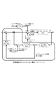
図1は第1実施例の操作反力生成制御装置を示す全体システム図である。図1において、1はステアリングホイール(操作入力手段)、2は減速ギヤ、3はモータ(アクチュエータ)、4はロータリエンコーダ(操作状態量検出手段)、5はステアリングシャフト、6はトルクセンサ(操作力検出手段)、7は車速センサ(車速検出手段)、8は操舵反力コントローラ(制御手段)である。
【0016】
前記ステアリングホイール1は、運転者が車両の方向変化の指令値を入力するための操作入力手段である。この操作入力手段としては、他にジョイスティックのようなレバー等であっても良い。
【0017】
前記減速ギヤ2は、モータ3の回転を減速してステアリングシャフト5に与える減速機構である。この減速ギヤ2としては、図1では平歯車を記したが、歯打ち音などが気になる場合には、ウォームなどで構成しても良い。
【0018】
前記モータ3は、前記ステアリングホイール1の操作反力を調整するアクチュエータである。このモータ3としては、DCサーボモータを用いても良いし、ブラシレスモータを用いても良い。また、十分なトルクが得られるのならば、減速ギヤ2を持たずに、モータ軸を直接ステアリングホイール1の軸としても構わない。
【0019】
前記ロータリエンコーダ4は、運転者の操作によって生じたステアリングホイール1の変位を、モータ軸の回転角度により間接的に検出する操作状態量検出手段である。なお、ロータリエンコーダ4では回転角度がわかるが、回転速度を検出するために、タコジェネレータをロータリエンコーダ4の代わりに取り付けても良い。さらに、モータ軸の回転を検出するようにしたが、ステアリングシャフト5の位置に同様にロータリエンコーダを取り付けても良い。但し、減速ギヤ2を介しているので角度分解能的には、モータ軸の回転を検出する方が細かく角度を検出できるため、モータ軸の回転を検出する位置の方が好ましい。
【0020】
前記トルクセンサ6は、ステアリングシャフト5の位置に設けられ、運転者のステアリングホイール1に対する操作力(ドライバ操舵トルク)を検出する。なお、トルクセンサ6は、電動パワーステアリングに用いられている一般的な構成のもので構わない。
【0021】
前記操舵反力コントローラ8は、ロータリエンコーダ4からの回転角度情報とトルクセンサ6からのドライバ操舵トルク情報と車速センサ7からの車速情報とを入力し、これらの情報に基づいて、モータ3への印加電流を演算し、モータ3を印加電流によって駆動する。なお、操舵反力コントローラ7の図示しないモータ駆動回路は、安定して電流を供給できるものとする。例えば、逆起電力の影響を受けにくいように、電流のサーボコントロールがされているものとする。
【0022】
次に、作用を説明する。
[角度検出時のフリクション推定作用]
図2はステアリングシャフト回転角αに基づいてフリクショントルクの推定を行なう第1実施例の操作反力生成制御ブロック図である。
トルクセンサ6の信号をドライバ操舵トルクTs(既知外乱)
フリクショントルクTf(未知外乱)
モータ慣性モーメントJs(但し、ステアリングシャフト換算であり、ステアリングホイール1の慣性モーメントも含む)
モータトルク定数Kt(但し、ステアリングシャフト換算)
モータ発生トルクTm=Kt・i(但し、ステアリングシャフト換算)
モータ印加電流 i
ステアリングシャフト回転角α
ステアリングシャフト回転角加速度α’’
とすると、運動方程式は以下のようになる。
Js・α’’=Ts+Tm+Tf …(1)
プラントに外乱Ts,Tfが加わらない状態では、
Js・α’’=Kt・i …(2)
と書けるので、伝達関数で表わすと、sをラプラス演算子として次のようになる。
α/i=Kt/(Js・s2)=P(s) …(3)
外乱除去の周波数帯をfc(Hz)として、ωc=2πfc(rad/s)と定義する。
外乱除去のローパスフィルタを、
H(s)=ωc2/(s+ωc)2 …(4)
とする。この状態で図2のように制御対象(プラント)の周りにコントローラを構成すると、図2のA部から推定されたフリクショントルクが電流値に換算して得られるので、これを図2のように入力電流にフィードバックする。こうしてフリクションが除去される。
【0023】
フィードバックの経路には、電流のリミッタが設けられており、例えば、補償されるべきフリクションが高々1Nmの場合には、1Nmに見合った電流値=1/Kt(A)でリミッタを設定すれば良い。
【0024】
リミッタを設ける理由としては、以下の効果も挙げられる。例えば、ωc=2πfc(rad/s)を高く設定した場合に、制御系にのるノイズなどによって、フリクショントルクが過大に、かつ、高周波ノイズとして推定されてしまう可能性がある。その結果、フリクション補償電流によってアクチュエータが駆動され、運転者にギクシャクした感じが伝わってしまうが、リミッタをいれて電流を飽和させることで、このような違和感を防止する効果もある。
【0025】
[操作反力生成制御作用]
従来、フリクションを除去する方法としては、フィードフォワードが盛んに行われていた。しかし、フィードフォワードによるフリクション除去では、以下の問題が発生する。
【0026】
例えば、プラントに1Nmのフリクションがあるだろうと思って、それを補償するための電流1Aを流したとする。しかし、実際にはフリクションが0.2Nmしかない場合には、0.8Nm分のトルクが運転者に伝わってしまい、操舵違和感につながる。このように、想定した対象(プラント)と実際のプラントの特性が異なった時に、柔軟に対応できないという問題がある。
【0027】
それならば、プラントの状態を探りながら制御するフィードバックを加えれば良いと考えるのは自然である。しかし、フィードバックでフリクションを除去する発明は見当たらない。フリクションで問題になるのは、静的なフリクションである。運転者が操舵しているときのフリクションはいわゆる動フリクションであり、これは操舵系のダンピングとしても寄与することから、むしろ好ましい場合もある。しかし、保舵状態から操舵開始する時は静フリクションになり、このフリクションが大きいと、まさに「ひっかかり」として運転者に感じとられてしまう。つまり、極低周波(定常状態)でのフリクションが除去されなければならない。
【0028】
このときに考えられるのは、一般的に制御において定常偏差を除去するために用いられる積分制御である。積分制御は誤差の積分値がゼロになるように作用するので、定常状態でのフリクション除去に有効なはずである。上述のように積分制御は定常偏差を除去できるので、位置コントロールなどにおいて、定常偏差が生じようとすると「じわじわと」偏差を除去する方向に力を加えていくものである。ここで「じわじわと」と記したのは、一般的に積分制御を大きく効かせると、閉ループ系全体の動特性が低下し、極端な場合には発散に至るためである。そのため、一般には積分定数はあまり大きく設定しない。つまり、定常偏差は徐々に除去され「じわじわと」目標値に近づいていくのが一般的である。したがって、このような方法では操舵開始と同時にフリクションを除去することは不可能であり、操舵開始したときの引っかかり感はそのままで、ハンドルを切っているうちに、じわじわと少し軽くなることになる。このように、単純に積分のフィードバックを加える方法では、期待する効果が得られないためフィードバックによるフリクション除去は今まで行われていなかった。
【0029】
本発明の外乱オブザーバも一つの積分制御である。しかし、一般的な積分と違うのは、外乱を除去する周波数領域をフィルタH(s)で設定することができることである。本発明のポイントは、このフィルタH(s)のカットオフ周波数を高く設定することである。こうすることによって定常偏差はもちろん、高周波の外乱までを推定し、除去することが理論的には可能である。
「理論的には」と書いたのは、実際には高周波の外乱を推定するためには、プラントの特性を高周波まで正しく把握することが必要であり、一般的には難しい。つまり、高周波外乱までを推定すると、高周波の誤った外乱推定値が得られ、これに基づいてフリクションを除去しようとすると高周波でガタガタ動き、運転者には妙にギクシャクしたような操舵系となる。そこで、本発明では、高周波外乱までを推定しながら、上記ギクシャク感を感じさせないように、外乱推定値にリミッタを設け、外乱推定値を一定値で飽和させてしまう方法を用いた。こうすることによって、操舵開始と同時に外乱推定値が立ち上がり、ある値で飽和することになる。
【0030】
次に、効果を説明する。
第1実施例の操作反力生成制御装置にあっては、下記に列挙する効果を得ることができる。
【0031】
(1)運転者が車両の方向変化の指令値を入力するためのステアリングホイール1と、該ステアリングホイール1に加わる操作反力を調整するモータ3と、該モータ3の発生力を制御する操舵反力コントローラ8と、を備えた操作反力生成制御装置において、運転者のステアリングホイール1に対するドライバ操舵トルクTsを検出するトルクセンサ6と、運転者の操作によって生じたステアリングシャフト回転角αを検出するロータリエンコーダ4と、を設け、前記操舵反力コントローラ8は、検出されたドライバ操舵トルクTsと、検出されたステアリングシャフト回転角αと、加えた制御入力に基づいて、モータ3及び減速ギヤ2によるアクチュエータ部のフリクションを推定するフリクション推定部と、推定されたフリクションを除去するように制御入力を変更するフリクション補償部と、を有するため、操作入力手段を操作したときのフリクションを合理的に推定し除去することで、微小なトルクで運転者に路面状況やそのほかの必要な情報を伝えることができると共に、操作系にフリクション感がなく操舵感の向上を望むことができる。
【0032】
すなわち、ステアリングホイール1に代表される操作入力手段を操作したときの、フリクションを合理的に推定し、除去するので、微小なトルクで運転者に路面状況やそのほかの必要な情報を伝えることができるという効果が生まれる。例えば、ステアバイワイヤの反力発生部にこのような仕組みを取り付けなかったら、ハンドル(ステアリングホイール1)を中立位置に戻すために大きなトルクを発生させなければならない。そのため、通常の操舵時にもそれらのトルクが邪魔になり、ハンドル操作に対しての復元トルクが大きくなったりする可能性がある。また、一般に操作系にフリクション感がないことは、「すっきり」したフィーリングになり、好ましいので、車両の操舵感が向上する効果が望める。
【0033】
(2)フリクション推定部は、制御入力と運転者操作力によって駆動されるモデルP(s)を持ち、ステアリングシャフト回転角αを、そのモデルP(s)の逆特性に通したときに求められる制御入力及び操作入力の合計の推定値と、実際の制御入力及び操作入力の合計値との差から、外乱として入力された力をフリクション推定値としたため、合理的なフリクション推定の構成を与えることができる。
【0034】
すなわち、従来のような、「きっとこうなるだろう」というようなフィードフォワードの制御ではなく、「実際に運転者は検出されたトルクで操舵しているし、アクチュエータにも検出されたエネルギーを加えているのだから、ハンドルはモデルによればこのくらい動くはずだ。もしも、それだけ動いていないのならば、それはフリクションなどの外乱によってアクチュエータの動きが拘束されているからだ。」ということを、制御ブロック図(図2)で構成し、外乱をフィードバックで推定することにより、必要かつ十分なフリクション推定が行われる。そのため、フリクショントルク除去を、タイミングが違うなどの妙な違和感を発生させずに行なうことが可能になる。
【0035】
(3)フリクション補償部は、フリクション推定値相当の電流にある上限(電流リミッタ)を設けて、その電流リミッタ以下のフリクションを除去するようにした、つまり、フリクションの上限値を定め、それ以上の推定値が得られてもフリクション推定値を飽和させるようにしたため、ギクシャク感を防止することができる。
【0036】
すなわち、フリクションを推定するときに、モデル誤差があったり、信号にノイズがあったりすると、それをフリクションと誤推定し、フリクション補償制御が振動的になったり、妙なギクシャク感を運転者に与える可能性がある。
【0037】
(4)フリクション推定部は、モデルP(s)の逆特性にあるローパスフィルタH(s)をかけて、フリクション除去の周波数帯域を特定するようにしたため、高周波でのノイズにより、(3)の効果で述べたようなギクシャク感が発生することを防止することができる。
【0038】
(5)車速を検出する車速センサ7を設け、フリクション補償部は、フリクション除去による補償を、検出車速が所定車速以下でのみ実施するようにしたため、フリクションと共にセルフアライニングトルクが除去されてしまう場合の、車両性能への影響を少なくすることができる。
【0039】
つまり、低速では問題にならないが、高速では中立付近の反力感が希薄になるため、低速でのみ本願の制御を実施することが望ましい。しかも、低速では、ハンドルの復元性などが大幅に改善されるメリットがある。
【0040】
(第2実施例)
第1実施例はステアリングシャフト回転角αを用いてフリクショントルクを推定したのに対し、第2実施例は操舵角速度ηを用いてフリクショントルクを推定するようにした例である。なお、システム構成は第1実施例の図1と同様であるので、図示並びに説明を省略する。
【0041】
次に、作用を説明する。
[角速度検出時のフリクション推定作用]
図3は操舵角速度ηに基づいてフリクショントルクの推定を行なう第2実施例の操作反力生成制御ブロック図である。操舵角速度ηを求めるためには、タコジェネレータの信号を用いるのが望ましいが、エンコーダからα(角度)を求めて、差分から操舵角速度ηを求めても良い。但し、この場合には操舵角速度ηの分解能が十分取れるように配慮をするべきである。
【0042】
上記と同様に、プラントに外乱Ts,Tfが加わらない状態では、
Js・η’=Kt・i …(5)
と書けるので、伝達関数で表わすと、sをラプラス演算子として次のようになる。
η/i=Kt/(Js・s)=Q(s) …(6)
外乱除去の周波数帯をfc(Hz)として、ωc=2πfc(rad/s)と定義する。
外乱除去のローパスフィルタを、
G(s)=ωc/(s+ωc) …(7)
とする。
この状態で図3のように制御対象(プラント)の周りにコントローラを構成すると、図2と同様に、図3のA部から推定されたフリクショントルクが電流値に換算して得られるので、これを図3のように入力電流にフィードバックする。こうしてフリクションが除去される。
【0043】
次に、効果を説明する。
この第2実施例の操作反力生成制御装置にあっては、第1実施例の(1)〜(5)の効果を得ることができる。但し、第1実施例の(1),(2)の効果は、下記の(1’),(2’)のように書き表される。
【0044】
(1’)運転者が車両の方向変化の指令値を入力するためのステアリングホイール1と、該ステアリングホイール1に加わる操作反力を調整するモータ3と、該モータ3の発生力を制御する操舵反力コントローラ8と、を備えた操作反力生成制御装置において、運転者のステアリングホイール1に対するドライバ操舵トルクTsを検出するトルクセンサ6と、運転者の操作によって生じた操舵角速度ηを検出するロータリエンコーダ4またはタコジェネレータと、を設け、前記操舵反力コントローラ8は、検出されたドライバ操舵トルクTsと、検出された操舵角速度ηと、加えた制御入力に基づいて、モータ3及び減速ギヤ2によるアクチュエータ部のフリクションを推定するフリクション推定部と、推定されたフリクションを除去するように制御入力を変更するフリクション補償部と、を有するため、操作入力手段を操作したときのフリクションを合理的に推定し除去することで、微小なトルクで運転者に路面状況やそのほかの必要な情報を伝えることができると共に、操作系にフリクション感がなく操舵感の向上を望むことができる。
【0045】
(2’)フリクション推定部は、制御入力と運転者操作力によって駆動されるモデルQ(s)を持ち、操舵角速度ηを、そのモデルQ(s)の逆特性に通したときに求められる制御入力及び操作入力の合計の推定値と、実際の制御入力及び操作入力の合計値との差から、外乱として入力された力をフリクション推定値としたため、合理的なフリクション推定の構成を与えることができる。
【0046】
(第3実施例)
まず、構成を説明する。
第3実施例は、本発明の操作反力生成制御装置を電動パワーステアリングの操舵反力発生部に適用した場合を記す。
【0047】
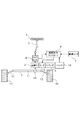
図4は、本発明の第3実施例に関わる車両用操舵装置のブロック図である。ステアリングホイール1と、舵取り動作を行なう舵取機構9とを連結するステアリングシャフト5に、ステアリングホイール1に加わる操舵トルクを検出するトルクセンサ6と操舵補助用のモータ3とが配置されている。
【0048】
前記ステアリングホイール1は、図示しない車室内部に運転者と対向するように、軸周りに回転可能に設けられている。舵取機構9は、ステアリングシャフト5の下端に一体形成されたピニオン10と、これに噛合するラック軸11とを備えるラック&ピニオン式の舵取り装置により構成される。
【0049】
前記ラック軸11は、図示しない車両前部に、左右方向へ摺動可能に固定されており、ラック軸11の両端は、左右のタイロッド12,13を介して操向用の車輪14,15に連結されている。操舵を補助するモータ3は、モータ3の発生トルクをステアリングシャフト5の回転トルクに変換するような減速ギア2を介して、ステアリングシャフト5に結合される。
【0050】
続いて、第3実施例の制御系を、図5に示す制御ブロック図を用いて説明する。
運転者によりステアリングホイール1が操作されると、機械的な連結により車輪14,15が操向される。この時の負荷によりトルクセンサ6は捩れ操舵トルクとして検出される。このトルクセンサ6の出力は、操舵補助用のモータ3を制御駆動する操舵反力コントローラ8に与えられる。
【0051】
前記操舵反力コントローラ8には、さらに、前記モータ3の回転角や回転速度を計測するためのロータリエンコーダ4もしくはタコジェネレータから出力される回転角度が入力されている。また、車両の走行速度を検出する車速センサ7等の信号も与えられている。
【0052】
前記操舵反力コントローラ8の出力は、モータ3に与えられており、操舵トルク・モータの回転角度・回転速度・車速等を用いて、モータ3の駆動電流を算出し、算出された駆動電流を内蔵するモータ電流センサによるモータ電流を参照しつつモータ3を制御駆動する。モータへ供給される電源は、バッテリ16により与えられる。
【0053】
[角度検出時のフリクション推定作用]
図6は、モータ角度αに基づいて静フリクション推定を行い、モータ回転速度に基づいて動フリクションを補償する第3実施例の操作反力生成制御ブロック図である。
トルクセンサの信号をドライバ操舵トルク: Ts(外乱既知)
フリクショントルクと路面からの入力トルク: Tf(未知外乱)
ステアリング系(モータ含む)の慣性モーメント: Js
モータトルク定数: Kt
モータ発生トルク: Tm
モータ印加電流: i
ステアリングシャフトの回転角: α=θ/減速比
とすると、運動方程式は以下のようになる。
Js・α’’=Ts+Tm+Tf …(1)
プラントに外乱Ts,Tfが加わらない状態では、
Js・α’’=Kt・i …(2)
と書けるので、伝達関数で表わすと、sをラプラス演算子として次のようになる。
α/i=Kt/(Js・s2)=P(s) …(3)
外乱除去の周波数帯をfc(Hz)として、ωc=2πfc(rad/s)と定義する。
外乱除去のローパスフィルタを、
H(s)=ωc2/(s+ωc)2 …(4)
とする。この状態で図6のように制御対象の周りにコントローラを構成すると、図6のA部から推定された未知外乱トルクが算出される。
【0054】
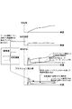
電動パワーステアリングにおいて、αに対する外乱(フリクショントルクと路面からの入力トルク)の関係は、図7のようになっており(外乱トルク=フリクショントルク+タイヤ復元トルク)、推定された未知外乱トルクをB部で微分(ハイパスフィルタ)することにより、微小転舵時の静フリクション相当を推測可能となる。
【0055】
上記静フリクション相当に加え、事前に分かっている動フリクションをC部から算出し、両者を加算してフリクションとする。それを電流値に換算し図5のように入力電流へフィードバックすることにより、フリクションが除去される。
【0056】
次に、効果を説明する。
この第3実施例の操作反力生成制御装置にあっては、下記に列挙する効果を得ることができる。
【0057】
(3) 運転者が車両の方向変化の指令値を入力するためのステアリングホイール1と、該ステアリングホイール1に加わる操作反力を調整するモータ3と、該モータ3の発生力を制御する操舵反力コントローラ8と、を備えた操作反力生成制御装置において、運転者のステアリングホイール1に対する操作力を検出するトルクセンサ6と、運転者の操作によって生じたステアリングシャフト回転角αを検出するロータリエンコーダ4と、を設け、操舵反力コントローラ8は、検出されたドライバ操舵トルクTsと、検出されたステアリングシャフト回転角αと、加えた制御入力に基づいて、モータ3及び減速ギア2によるアクチュエータ部の静フリクションを推定するフリクション推定部(B部)と、ステアリングシャフト回転角速度α’に応じたアクチュエータ部の動フリクションを記憶したフリクション記憶部(C部)と、推定された静フリクションと、記憶された動フリクションに基づいて、両フリクションを除去するように制御入力を変更するフリクション補償部と、を有するため、静フリクションと動フリクションの両方を補償することが可能であり、操作系のフリクション感をなくし、車両の操舵感を向上する効果が期待できる。また、タイヤを介して伝わる路面状況等の必要なインフォメーションを伝達できる。
【0058】
(4) フリクション補償部は、フリクション推定部(B部)の出力にハイパスフィルタをかけた値と、フリクション記憶部(C部)から出力される値と、に応じて制御入力を変更するため、微小転舵時の静フリクション相当を推測可能となり、微小転舵時の操舵感を向上させることができる。
【0059】
(第4実施例)
システム構成は第3実施例の図4と同様であるので、図示並びに説明を省略する。
【0060】
次に、作用を説明する。
[角度検出時のフリクション推定作用]
図8は、第4実施例の操作反力生成制御ブロック図である。未知外乱トルク算出の過程は第3実施例と同じであるため、説明は省略する。
【0061】
第4実施例では、外乱トルクの推測値に、動摩擦相当のリミッタを設けた(D部)。その後、1以下のゲイン第1ゲインG1を掛けた第1フリクション補償値(E部)を算出する。それに加え、事前に分かっている動フリクションをステアリングシャフト回転角速度α’から算出し、その後、1以下のゲイン第2ゲインG2を掛けた第2フリクション補償値(F部)を算出する。そして、両者を加算することによりフリクション補償値とする。
【0062】
また、第1ゲインG1と第2ゲインG2の和を1以下とすることで、両者を加算して算出されるフリクションは、より実際のフリクション値に近くなるので、より自然な操舵フィーリングを実現できる。
【0063】
また、車速が高くなると一般に転舵速度が遅くなり、ハンドルが停止→微小操作→停止が繰り返されることになる。そのような場合は、静摩擦→動摩擦の変化が発生しがちになるので、高車速の場合は第1ゲインG1を高くして、第2ゲインG2を低くすると、高車速時のフリクション感をなくすことができる。
【0064】
また、電動パワーステアリングの場合、操舵中心付近の操舵力が低い。操舵力が低いと微小なトルク変動を感じ易いので、操舵角が小さいときは、第1ゲインG1を高くして、第2ゲインG2を低くすると、微小転舵時のフリクション感をなくすことができる。
【0065】
さらに、転舵速度が速い場合は、動フリクションだけとなるので、転舵速度が速い場合は、第1ゲインG1を小さくして、第2ゲインG2を高くすると、フリクション感をなくすことができる。
【0066】
次に、効果を説明する。
この第4実施例の操作反力生成制御装置にあっては、下記に列挙する効果を得ることができる。
【0067】
(5) フリクション補償部は、フリクション推定部(D部)の出力に1以下の第1ゲインG1を乗じた第1フリクション補償値と、フリクション記憶部(C部)の出力に1以下の第2ゲインG2を乗じた第2フリクション補償値との加算値をフリクション補償値とし、さらに、第1ゲインG1と第2ゲインG2との加算値を、1以下としたため、フリクション補償値を実際のフリクション値に近づけることができ、より自然な操舵フィーリングを実現できる。
【0068】
(6) 車速を検出する車速センサ7を設け、第1フリクション補償部(E部)は、高車速時には、第1ゲインG1を高くし、かつ、第2フリクション補償部(F部)は、第2ゲインG2を低くするため、高車速時のフリクション感をなくして操舵感を向上させることができる。
【0069】
(7) 第1フリクション補償部(E部)は、操舵角が小さい場合には、第1ゲインG1を高くし、かつ、第2フリクション補償部(F部)は、第2ゲインG2を低くするため、微小転舵時のトルク変動を抑制して操舵感を向上させることができる。
【0070】
(8) 第1フリクション補償部(E部)は、操舵速度が速い場合には、第1ゲインG1を低くし、かつ、第2フリクション補償部(F部)は、第2ゲインG2を高くするため、操舵速度が速い場合のフリクション感をなくすことができる。
【0071】
以上、本発明の操作反力生成制御装置を第1実施例〜第4実施例に基づき説明してきたが、具体的な構成については、これらの実施例に限られるものではなく、特許請求の範囲の各請求項に係る発明の要旨を逸脱しない限り、設計の変更や追加等は許容される。
【0072】
例えば、第1実施例と第2実施例では、ステアバイワイヤの反力アクチュエータについて説明したが、電動パワーステアリングでも同様にフリクションを除去できる。
但し、電動パワーステアリングでは、フリクションだけでなくタイヤで発生するセルフアライニングトルクも除去してしまうので、図2及び図3のフリクション補償電流をフィードバックするところにリミッタは必須になる。
【0073】
また、第1実施例〜第4実施例では、モータをアクチュエータ駆動に用いたが、油圧系を構成して同様の制御を行なうことによっても、アクチュエータのフリクション除去が可能なことはいうまでもない。
【図面の簡単な説明】
【図1】第1実施例の操作反力生成制御装置を示す全体システム図である。
【図2】第1実施例装置においてステアリングシャフト回転角に基づいてフリクショントルクの推定を行なう操作反力生成制御ブロック図である。
【図3】第2実施例装置において操舵角速度に基づいてフリクショントルクの推定を行なう操作反力生成制御ブロック図である。
【図4】第3実施例の操作反力生成制御装置を示す全体システム図である。
【図5】第3実施例の制御系を示すブロック図である。
【図6】第3実施例装置においてステアリングシャフト回転角に基づいてフリクショントルクの推定を行なう操作反力生成制御ブロック図である。
【図7】第3実施例の作動特性図である。
【図8】第4実施例装置においてステアリングシャフト回転角に基づいてフリクショントルクの推定を行なう操作反力生成制御ブロック図である。
【図9】第4実施例の作動特性図である。
【符号の説明】
1 ステアリングホイール(操作入力手段)
2 減速ギヤ
3 モータ(アクチュエータ)
4 ロータリエンコーダ(操作状態量検出手段)
5 ステアリングシャフト
6 トルクセンサ(操作力検出手段)
7 車速センサ(車速検出手段)
8 操舵反力コントローラ(制御手段)
9 舵取機構
10 ピニオン
11 ラック軸
12 タイロッド
13 タイロッド
14 車輪
15 車輪
16 バッテリ[0001]
TECHNICAL FIELD OF THE INVENTION
The present invention belongs to the technical field of an operation reaction force generation control device that generates a steering reaction force transmitted to a driver by steer-by-wire, electric power steering, or the like.
[0002]
[Prior art]
Conventionally, there has been proposed an electric power steering system in which a range in which the steering angular velocity is small is determined to be stationary, and dither is added to a control current to convert static friction into dynamic friction, thereby causing vibration ( For example, see Patent Document 1). Further, the steering torque is differentiated, and it is determined that the driver has started steering based on the magnitude of the differentiated value (edge), and the static friction force is estimated from the magnitude and compensated (for example, see Patent Reference 2). In addition, in order to reduce the Coulomb friction, it is customary to add an offset current corresponding to friction removal in advance by looking at the direction of the steering speed.
[0003]
[Patent Document 1]
JP-A-2002-46632
[Patent Document 2]
JP-A-2000-103349
[0004]
[Problems to be solved by the invention]
However, in the prior art, the friction torque is not rationally estimated and removed by feedback, but is determined in a feed-forward manner based on the conditions of the vehicle (steering speed and direction), and the influence of the friction is determined. I was trying to remove it.
[0005]
For this reason, there is a problem that the driver will feel uncomfortable if the rules are not followed. For example, if measures are taken to add dither where the steering angular velocity is small, dither must be applied in most of the driving conditions, and it is feared that the vibration will be transmitted to the driver. There is a problem that it is not preferable from the viewpoint of this.
[0006]
In addition, even if the edge of the steering torque is extracted, friction compensation is likely to be performed because the torque is differentiated. There was a problem of being late.
[0007]
Furthermore, when the offset current is switched in the direction of the steering speed, the friction torque frequently changes the sign during a minute steering operation, and the hunting of the friction compensation current is transmitted to the driver. There was also.
[0008]
All of the above problems have been caused by trying to compensate for friction in a feed-forward manner based on uncertain detection information.
[0009]
The present invention has been made in view of the above problems, and rationally estimates and removes friction when operating the operation input means, so that the driver can use a small amount of torque to reduce road surface conditions and other necessary conditions. It is an object of the present invention to provide an operation reaction force generation control device that can transmit information and that can improve steering feeling without friction in an operation system.
[0010]
[Means for Solving the Problems]
In order to achieve the above object, in the present invention,
An operation input means for the driver to input a command value for changing the direction of the vehicle, an actuator for adjusting an operation reaction force applied to the operation input means, and a control means for controlling a generated force of the actuator. In the operation reaction force generation control device,
Operating force detecting means for detecting an operating force on the driver's operation input means,
Operation state amount detection means for detecting displacement or speed of the operation input means caused by the operation of the driver,
The control means,
Based on the detected operation force, the detected displacement or speed of the operation input unit, and the applied control input, a friction estimation unit that estimates the friction of the actuator unit,
A friction compensator that changes the control input so as to remove the estimated friction,
It is characterized by having.
[0011]
Here, the `` friction estimating unit '' has, for example, a model driven by a control input and a driver's operation force, and when an operation state amount by displacement or speed of the operation input means is passed through the inverse characteristic of the model. Based on the difference between the estimated value of the sum of the control input and the operation input that is obtained and the total value of the actual control input and the operation input, the force input as the disturbance is used as the estimated friction value.
[0012]
【The invention's effect】
Therefore, in the operation reaction force generation control device of the present invention, the friction at the time of operating the operation input means is rationally estimated and removed, so that the driver can use a small amount of torque to give the road surface condition and other necessary information. The effect of being able to convey is created. In addition, the effect of improving the steering feeling of the vehicle can be expected by eliminating the frictional feeling of the operation system.
[0013]
BEST MODE FOR CARRYING OUT THE INVENTION
Hereinafter, an embodiment for realizing the operation reaction force generation control device of the present invention will be described based on first to fourth examples shown in the drawings.
[0014]
(First embodiment)
First, the configuration will be described.
The first embodiment describes a case where the operation reaction force generation control device of the present invention is applied to a steering reaction force generation unit of a steer-by-wire.
[0015]
FIG. 1 is an overall system diagram showing the operation reaction force generation control device of the first embodiment. In FIG. 1, 1 is a steering wheel (operation input means), 2 is a reduction gear, 3 is a motor (actuator), 4 is a rotary encoder (operation state quantity detection means), 5 is a steering shaft, and 6 is a torque sensor (operation force). Detecting means), 7 is a vehicle speed sensor (vehicle speed detecting means), and 8 is a steering reaction force controller (control means).
[0016]
The
[0017]
The
[0018]
The
[0019]
The rotary encoder 4 is an operation state amount detection unit that indirectly detects a displacement of the
[0020]
The
[0021]
The steering reaction force controller 8 inputs rotation angle information from the rotary encoder 4, driver steering torque information from the
[0022]
Next, the operation will be described.
[Effect of friction estimation at angle detection]
FIG. 2 is a block diagram of the operation reaction force generation control of the first embodiment for estimating the friction torque based on the steering shaft rotation angle α.
The signal of the
Friction torque Tf (unknown disturbance)
Motor inertia moment Js (However, this is converted into a steering shaft and includes the inertia moment of the steering wheel 1)
Motor torque constant Kt (However, converted to steering shaft)
Motor generated torque Tm = Kt · i (However, converted to steering shaft)
Motor applied current i
Steering shaft rotation angle α
Steering shaft rotation angular acceleration α ''
Then, the equation of motion is as follows.
Js · α ″ = Ts + Tm + Tf (1)
In the state where disturbances Ts and Tf are not added to the plant,
Js · α ″ = Kt · i (2)
Therefore, when expressed by a transfer function, s is expressed as a Laplace operator as follows.
α / i = Kt / (Js · s 2 ) = P (s) (3)
The frequency band of disturbance elimination is defined as fc (Hz), and ωc = 2πfc (rad / s).
A low-pass filter for disturbance rejection,
H (s) = ωc 2 / (S + ωc) 2 … (4)
And In this state, if a controller is configured around the control target (plant) as shown in FIG. 2, the friction torque estimated from the portion A in FIG. 2 can be obtained by converting it into a current value. Feedback to input current. Thus, friction is removed.
[0023]
A current limiter is provided in the feedback path. For example, when the friction to be compensated is at most 1 Nm, the limiter may be set at a current value = 1 / Kt (A) corresponding to 1 Nm. .
[0024]
The reason for providing the limiter also includes the following effects. For example, when ωc = 2πfc (rad / s) is set high, the friction torque may be excessively estimated as high-frequency noise due to noise on the control system. As a result, the actuator is driven by the friction compensation current, and a jerky feeling is transmitted to the driver. However, saturation of the current by inserting a limiter also has an effect of preventing such a feeling of strangeness.
[0025]
[Operation reaction force generation control action]
Conventionally, feedforward has been actively used as a method for removing friction. However, the following problem occurs in the friction removal by the feed forward.
[0026]
For example, suppose that there is 1 Nm of friction in the plant, and a current of 1 A is applied to compensate for it. However, when the friction is actually only 0.2 Nm, the torque of 0.8 Nm is transmitted to the driver, which leads to a feeling of steering discomfort. As described above, there is a problem that it is not possible to flexibly cope with the case where the characteristics of the assumed target (plant) and the actual plant are different.
[0027]
Then, it is natural to think that it is sufficient to add feedback for controlling while exploring the state of the plant. However, there is no invention that eliminates friction by feedback. The problem with friction is static friction. The friction when the driver is steering is so-called dynamic friction, which may be rather preferable because it also contributes to damping of the steering system. However, when the steering is started from the steering-holding state, static friction occurs. If the friction is large, the driver feels that the vehicle is just "jammed". That is, friction at an extremely low frequency (steady state) must be removed.
[0028]
What can be considered at this time is integral control which is generally used to eliminate a steady-state error in control. Since the integral control works so that the integral value of the error becomes zero, it should be effective for removing friction in a steady state. As described above, since the integral control can remove the steady-state deviation, in the case of position control or the like, if a steady-state deviation is to occur, a force is gradually applied in a direction to remove the deviation. Here, the term “slowly” is used because the dynamic characteristics of the entire closed-loop system are generally reduced when the integral control is greatly effective, and divergence occurs in extreme cases. Therefore, generally, the integration constant is not set so large. That is, the steady-state deviation is generally gradually removed and gradually approaches the target value. Therefore, in such a method, it is impossible to remove the friction at the same time as the start of the steering operation, and the feeling of being stuck at the start of the steering operation is kept as it is, and while the steering wheel is being turned, the lightness gradually decreases. As described above, since the expected effect cannot be obtained by the method of simply adding the feedback of the integration, the friction removal by the feedback has not been performed until now.
[0029]
The disturbance observer of the present invention is one integral control. However, the difference from the general integration is that the frequency domain in which disturbance is removed can be set by the filter H (s). The point of the present invention is to set the cutoff frequency of the filter H (s) high. By doing so, it is theoretically possible to estimate and remove not only the steady-state deviation but also the high-frequency disturbance.
The fact that "theoretically" is written is that it is generally difficult to estimate a high-frequency disturbance because it is necessary to correctly understand the characteristics of a plant up to a high frequency. In other words, when estimation is made up to the high-frequency disturbance, an erroneous disturbance estimation value of a high frequency is obtained, and if the friction is removed based on the estimated value, the steering system rattles at a high frequency, resulting in a steering system that is strangely jerky to the driver. Therefore, in the present invention, a method is used in which a limiter is provided for the disturbance estimation value so that the above-mentioned jerky feeling is not felt while estimating the high-frequency disturbance, and the disturbance estimation value is saturated at a constant value. By doing so, the disturbance estimation value rises at the same time as the start of steering and saturates at a certain value.
[0030]
Next, effects will be described.
In the operation reaction force generation control device of the first embodiment, the following effects can be obtained.
[0031]
(1) A
[0032]
That is, the friction when the operation input means represented by the
[0033]
(2) The friction estimation unit has a model P (s) driven by a control input and a driver's operation force, and is obtained when the steering shaft rotation angle α is passed through the inverse characteristic of the model P (s). Given the difference between the estimated value of the sum of the control input and the operation input and the sum of the actual control input and the operation input, the force input as the disturbance is used as the estimated friction value, so that a reasonable friction estimation configuration is provided. Can be.
[0034]
In other words, instead of the conventional feed-forward control such as "it will be this", "the driver is actually steering with the detected torque, and the detected energy is applied to the actuator. Therefore, the handle should move this much according to the model, if not, because the movement of the actuator is constrained by disturbances such as friction. " By constructing the diagram (FIG. 2) and estimating the disturbance by feedback, necessary and sufficient friction estimation is performed. Therefore, it is possible to remove the friction torque without causing strange strangeness such as different timing.
[0035]
(3) The friction compensating unit sets an upper limit (current limiter) for the current corresponding to the estimated friction value, and removes the friction below the current limiter. That is, the friction compensating unit determines the upper limit value of the friction and sets the upper limit of the friction. Even if the estimated value is obtained, the friction estimated value is saturated, so that the jerky feeling can be prevented.
[0036]
That is, when estimating friction, if there is a model error or a signal has noise, it is erroneously estimated as friction, and the friction compensation control becomes oscillatory or gives a strange jerky feeling to the driver. there is a possibility.
[0037]
(4) The friction estimating unit applies the low-pass filter H (s) having the inverse characteristic of the model P (s) to specify the frequency band of the friction elimination. It is possible to prevent the occurrence of the jerky feeling as described in the effect.
[0038]
(5) The
[0039]
That is, at low speeds, there is no problem, but at high speeds, the reaction force near neutral becomes weak. Therefore, it is desirable to execute the control of the present invention only at low speeds. In addition, at low speed, there is an advantage that the restorability of the steering wheel is greatly improved.
[0040]
(Second embodiment)
In the first embodiment, the friction torque is estimated using the steering shaft rotation angle α, whereas in the second embodiment, the friction torque is estimated using the steering angular velocity η. Since the system configuration is the same as that of the first embodiment shown in FIG. 1, illustration and description are omitted.
[0041]
Next, the operation will be described.
[Effect of friction estimation when detecting angular velocity]
FIG. 3 is an operation reaction force generation control block diagram of the second embodiment for estimating the friction torque based on the steering angular velocity η. To obtain the steering angular velocity η, it is desirable to use the signal of the tachometer. However, it is also possible to obtain α (angle) from the encoder and obtain the steering angular velocity η from the difference. However, in this case, care should be taken so that the resolution of the steering angular velocity η can be sufficiently obtained.
[0042]
As described above, in a state where disturbances Ts and Tf are not applied to the plant,
Js · η ′ = Kt · i (5)
Therefore, when expressed by a transfer function, s is expressed as a Laplace operator as follows.
η / i = Kt / (Js · s) = Q (s) (6)
The frequency band of disturbance elimination is defined as fc (Hz), and ωc = 2πfc (rad / s).
A low-pass filter for disturbance rejection,
G (s) = ωc / (s + ωc) (7)
And
In this state, if a controller is configured around the control target (plant) as shown in FIG. 3, the friction torque estimated from the portion A in FIG. 3 is obtained by converting it into a current value, as in FIG. Is fed back to the input current as shown in FIG. Thus, friction is removed.
[0043]
Next, effects will be described.
In the operation reaction force generation control device of the second embodiment, the effects (1) to (5) of the first embodiment can be obtained. However, the effects (1) and (2) of the first embodiment are expressed as the following (1 ′) and (2 ′).
[0044]
(1 ′) A
[0045]
(2 ′) The friction estimating unit has a model Q (s) driven by the control input and the driver's operation force, and controls the steering angular velocity η when the steering angular velocity η is passed through the inverse characteristic of the model Q (s). From the difference between the estimated value of the sum of the input and the operation input and the total value of the actual control input and the operation input, the force input as the disturbance is used as the friction estimation value, so that a reasonable friction estimation configuration can be provided. it can.
[0046]
(Third embodiment)
First, the configuration will be described.
The third embodiment describes a case where the operation reaction force generation control device of the present invention is applied to a steering reaction force generation unit of an electric power steering.
[0047]
FIG. 4 is a block diagram of a vehicle steering system according to a third embodiment of the present invention. A
[0048]
The
[0049]
The rack shaft 11 is fixed to a front portion of a vehicle (not shown) so as to be slidable in the left and right direction. Both ends of the rack shaft 11 are connected to
[0050]
Next, a control system according to a third embodiment will be described with reference to a control block diagram shown in FIG.
When the driver operates the
[0051]
The steering reaction force controller 8 is further input with a rotation angle output from a rotary encoder 4 or a tachometer for measuring the rotation angle and rotation speed of the
[0052]
The output of the steering reaction force controller 8 is given to the
[0053]
[Effect of friction estimation at angle detection]
FIG. 6 is an operation reaction force generation control block diagram of the third embodiment that performs static friction estimation based on the motor angle α and compensates for dynamic friction based on the motor rotation speed.
Driver steering torque: Ts (disturbance known)
Friction torque and road input torque: Tf (unknown disturbance)
Moment of inertia of steering system (including motor): Js
Motor torque constant: Kt
Motor generated torque: Tm
Motor applied current: i
Rotation angle of steering shaft: α = θ / reduction ratio
Then, the equation of motion is as follows.
Js · α ″ = Ts + Tm + Tf (1)
In the state where disturbances Ts and Tf are not added to the plant,
Js · α ″ = Kt · i (2)
Therefore, when expressed by a transfer function, s is expressed as a Laplace operator as follows.
α / i = Kt / (Js · s 2 ) = P (s) (3)
The frequency band of disturbance elimination is defined as fc (Hz), and ωc = 2πfc (rad / s).
A low-pass filter for disturbance rejection,
H (s) = ωc 2 / (S + ωc) 2 … (4)
And In this state, when a controller is configured around the control target as shown in FIG. 6, the unknown disturbance torque estimated from the part A in FIG. 6 is calculated.
[0054]
In the electric power steering, the relationship between the disturbance (the friction torque and the input torque from the road surface) with respect to α is as shown in FIG. 7 (disturbance torque = friction torque + tire restoration torque), and the estimated unknown disturbance torque is represented by B By differentiating (high-pass filter) in the section, it is possible to estimate the equivalent of static friction at the time of minute steering.
[0055]
In addition to the static friction, a previously known dynamic friction is calculated from the part C, and both are added to be a friction. By converting it into a current value and feeding it back to the input current as shown in FIG. 5, friction is removed.
[0056]
Next, effects will be described.
In the operation reaction force generation control device of the third embodiment, the following effects can be obtained.
[0057]
(3) A
[0058]
(4) The friction compensator changes the control input according to the value obtained by applying a high-pass filter to the output of the friction estimator (B) and the value output from the friction storage (C). It is possible to estimate the equivalent of static friction at the time of minute turning, and it is possible to improve the steering feeling at the time of minute turning.
[0059]
(Fourth embodiment)
Since the system configuration is the same as that of FIG. 4 of the third embodiment, illustration and description are omitted.
[0060]
Next, the operation will be described.
[Effect of friction estimation at angle detection]
FIG. 8 is an operation reaction force generation control block diagram of the fourth embodiment. Since the process of calculating the unknown disturbance torque is the same as that of the third embodiment, the description is omitted.
[0061]
In the fourth embodiment, the estimated value of the disturbance torque is provided with a limiter equivalent to dynamic friction (D part). Thereafter, a first friction compensation value (E part) multiplied by a first gain G1 of 1 or less is calculated. In addition, the dynamic friction that is known in advance is calculated from the steering shaft rotation angular velocity α ′, and then a second friction compensation value (F section) is calculated by multiplying the gain by a gain of 2 or less. Then, the two are added to obtain a friction compensation value.
[0062]
Further, by setting the sum of the first gain G1 and the second gain G2 to 1 or less, the friction calculated by adding the two becomes closer to the actual friction value, thereby realizing a more natural steering feeling. it can.
[0063]
Also, as the vehicle speed increases, the steering speed generally decreases, and the steering wheel stops, minute operation, and stop are repeated. In such a case, a change from static friction to dynamic friction tends to occur. Therefore, when the vehicle speed is high, the first gain G1 is increased and the second gain G2 is reduced, thereby eliminating the frictional feeling at a high vehicle speed. Can be.
[0064]
In the case of electric power steering, the steering force near the steering center is low. When the steering force is low, a slight torque fluctuation is easily felt. Therefore, when the steering angle is small, the first gain G1 is increased and the second gain G2 is decreased, so that the feeling of friction at the time of minute steering can be eliminated. .
[0065]
Furthermore, when the steering speed is high, only dynamic friction is involved. Therefore, when the steering speed is high, the first gain G1 is reduced and the second gain G2 is increased, so that the feeling of friction can be eliminated.
[0066]
Next, effects will be described.
In the operation reaction force generation control device of the fourth embodiment, the following effects can be obtained.
[0067]
(5) The friction compensating unit is configured to multiply the output of the friction estimating unit (D unit) by a first gain G1 of 1 or less and a second friction compensation value of 1 or less to the output of the friction storage unit (C unit). The sum of the gain G2 and the second friction compensation value is used as the friction compensation value, and the sum of the first gain G1 and the second gain G2 is set to 1 or less. , And a more natural steering feeling can be realized.
[0068]
(6) A
[0069]
(7) When the steering angle is small, the first friction compensator (E) increases the first gain G1, and the second friction compensator (F) decreases the second gain G2. Therefore, it is possible to improve the steering feeling by suppressing the torque fluctuation at the time of minute turning.
[0070]
(8) When the steering speed is high, the first friction compensator (E) lowers the first gain G1, and the second friction compensator (F) increases the second gain G2. Therefore, it is possible to eliminate the feeling of friction when the steering speed is high.
[0071]
As described above, the operation reaction force generation control device of the present invention has been described based on the first to fourth embodiments. However, the specific configuration is not limited to these embodiments, and claims Changes and additions of the design are permitted without departing from the gist of the invention according to each of the claims.
[0072]
For example, in the first embodiment and the second embodiment, the steer-by-wire reaction force actuator has been described, but the friction can be similarly removed by the electric power steering.
However, in the electric power steering, not only the friction but also the self-aligning torque generated in the tire is removed. Therefore, a limiter is indispensable for feeding back the friction compensation current shown in FIGS.
[0073]
In the first to fourth embodiments, the motor is used for driving the actuator. However, it is needless to say that the friction can be removed from the actuator by configuring the hydraulic system and performing the same control. .
[Brief description of the drawings]
FIG. 1 is an overall system diagram showing an operation reaction force generation control device according to a first embodiment.
FIG. 2 is an operation reaction force generation control block diagram for estimating a friction torque based on a steering shaft rotation angle in the device of the first embodiment.
FIG. 3 is an operation reaction force generation control block diagram for estimating a friction torque based on a steering angular velocity in the device of the second embodiment.
FIG. 4 is an overall system diagram showing an operation reaction force generation control device according to a third embodiment.
FIG. 5 is a block diagram illustrating a control system according to a third embodiment.
FIG. 6 is an operation reaction force generation control block diagram for estimating a friction torque based on a steering shaft rotation angle in the device of the third embodiment.
FIG. 7 is an operation characteristic diagram of the third embodiment.
FIG. 8 is an operation reaction force generation control block diagram for estimating a friction torque based on a steering shaft rotation angle in the device of the fourth embodiment.
FIG. 9 is an operation characteristic diagram of the fourth embodiment.
[Explanation of symbols]
1 Steering wheel (operation input means)
2 Reduction gear
3 Motor (actuator)
4 rotary encoder (operation state quantity detection means)
5 Steering shaft
6. Torque sensor (operating force detecting means)
7 Vehicle speed sensor (vehicle speed detection means)
8. Steering reaction force controller (control means)
9 Steering mechanism
10 pinions
11 Rack axis
12 Tie rod
13 Tie rod
14 wheels
15 wheels
16 Battery
Claims (10)
運転者の操作入力手段に対する操作力を検出する操作力検出手段と、
運転者の操作によって生じた操作入力手段の変位または速度を検出する操作状態量検出手段と、を設け、
前記制御手段は、
上記検出された操作力と、上記検出された操作入力手段の変位または速度と、加えた制御入力に基づいて、アクチュエータ部のフリクションを推定するフリクション推定部と、
推定されたフリクションを除去するように制御入力を変更するフリクション補償部と、
を有することを特徴とする操作反力生成制御装置。An operation input means for the driver to input a command value for changing the direction of the vehicle, an actuator for adjusting an operation reaction force applied to the operation input means, and a control means for controlling a generated force of the actuator. In the operation reaction force generation control device,
Operating force detecting means for detecting an operating force on the driver's operation input means,
Operation state amount detection means for detecting displacement or speed of the operation input means caused by the operation of the driver,
The control means,
Based on the detected operation force, the detected displacement or speed of the operation input unit, and the applied control input, a friction estimation unit that estimates the friction of the actuator unit,
A friction compensator that changes the control input so as to remove the estimated friction,
An operation reaction force generation control device, comprising:
前記フリクション推定部は、制御入力と運転者操作力によって駆動されるモデルを持ち、前記操作入力手段の変位または速度による操作状態量を、そのモデルの逆特性に通したときに求められる制御入力及び操作入力の合計の推定値と、実際の制御入力及び操作入力の合計値との差から、外乱として入力された力をフリクション推定値とすることを特徴とする操作反力生成制御装置。The operation reaction force generation control device according to claim 1,
The friction estimation unit has a model driven by a control input and a driver's operation force, and a control input obtained when an operation state amount by displacement or speed of the operation input unit is passed through the inverse characteristic of the model. An operation reaction force generation control device, wherein a force input as a disturbance is used as a friction estimated value based on a difference between an estimated value of a total of operation inputs and a total value of an actual control input and an operation input.
前記フリクション補償部は、フリクション推定値にある上限を設けて、その上限値以下のフリクションを除去することを特徴とする操作反力生成制御装置。The operation reaction force generation control device according to claim 1 or 2,
The operation reaction force generation control device, wherein the friction compensating unit sets an upper limit on the estimated friction value, and removes a friction that is equal to or less than the upper limit value.
前記フリクション推定部は、モデルの逆特性にあるローパスフィルタをかけて、フリクション除去の周波数帯域を特定することを特徴とする操作反力生成制御装置。The operation reaction force generation control device according to claim 2,
The operation reaction force generation control device, wherein the friction estimating unit applies a low-pass filter having an inverse characteristic of the model to specify a frequency band for removing friction.
車速を検出する車速検出手段を設け、
前記フリクション補償部は、フリクション除去による補償を、検出車速が所定車速以下でのみ実施することを特徴とする操作反力生成制御装置。The operation reaction force generation control device according to any one of claims 1 to 4,
Providing vehicle speed detection means for detecting vehicle speed,
The operation reaction force generation control device, wherein the friction compensating unit performs compensation by removing the friction only when the detected vehicle speed is equal to or lower than a predetermined vehicle speed.
運転者の操作入力手段に対する操作力を検出する操作力検出手段と、
運転者の操作によって生じた操作入力手段の変位または速度を検出する操作状態量検出手段と、を設け、
前記制御手段は、
上記検出された操作力と上記検出された操作入力手段の変位または速度と、加えた制御入力に基づいて、アクチュエータ部のフリクションを推定するフリクション推定部と、
前記操作入力手段の速度に応じたアクチュエータ部のフリクションを記憶したフリクション記憶部と、
上記推定されたフリクションと、上記記憶されたフリクションに基づいて、両フリクションを除去するように制御入力を変更するフリクション補償部と、
を有することを特徴とする操作反力生成制御装置。An operation input means for the driver to input a command value for changing the direction of the vehicle, an actuator for adjusting an operation reaction force applied to the operation input means, and a control means for controlling a generated force of the actuator. In the operation reaction force generation control device,
Operating force detecting means for detecting an operating force on the driver's operation input means,
Operation state amount detection means for detecting displacement or speed of the operation input means caused by the operation of the driver,
The control means,
Based on the detected operation force and the detected displacement or speed of the operation input unit, based on the applied control input, a friction estimation unit that estimates the friction of the actuator unit,
A friction storage unit that stores the friction of the actuator unit according to the speed of the operation input unit,
A friction compensator that changes a control input so as to remove both frictions based on the estimated friction and the stored friction;
An operation reaction force generation control device, comprising:
前記フリクション補償部は、フリクション推定部の出力にハイパスフィルタをかけた値と、フリクション記憶部から出力される値と、に応じて制御入力を変更することを特徴とする操作反力生成制御装置。The operation reaction force generation control device according to claim 6,
The operation reaction force generation control device, wherein the friction compensator changes a control input according to a value obtained by applying a high-pass filter to an output of the friction estimator and a value output from a friction memory.
前記フリクション補償部は、フリクション推定部の出力に1以下の第1ゲインを乗じた値と、フリクション記憶部の出力に1以下の第2ゲインを乗じた値との加算値に応じて制御出力を変更し、
前記第1ゲインと第2ゲインとの加算値を、1以下としたことを特徴とする操作反力生成制御装置。The operation reaction force generation control device according to claim 6 or 7,
The friction compensator outputs a control output according to a sum of a value obtained by multiplying the output of the friction estimator by a first gain of 1 or less and a value obtained by multiplying the output of the friction storage by a second gain of 1 or less. change,
An operation reaction force generation control device, wherein an added value of the first gain and the second gain is set to 1 or less.
車速を検出する車速検出手段を設け、
前記フリクション補償部は、上記検出された車速に応じて、前記第1ゲインと第2ゲインの少なくとも一方を変更することを特徴とする操作反力生成制御装置。The operation reaction force generation control device according to claim 7,
Providing vehicle speed detection means for detecting vehicle speed,
The control device according to claim 1, wherein the friction compensator changes at least one of the first gain and the second gain according to the detected vehicle speed.
前記フリクション補償部は、上記検出された操作入力手段の変位または速度に応じて、前記第1ゲインと第2ゲインの少なくとも一方を変更することを特徴とする操作反力生成制御装置。The operation reaction force generation control device according to claim 8,
The operation reaction force generation control device, wherein the friction compensator changes at least one of the first gain and the second gain in accordance with the detected displacement or speed of the operation input means.
Priority Applications (1)
| Application Number | Priority Date | Filing Date | Title |
|---|---|---|---|
| JP2003193249A JP4349016B2 (en) | 2003-01-30 | 2003-07-08 | Operation reaction force generation controller |
Applications Claiming Priority (2)
| Application Number | Priority Date | Filing Date | Title |
|---|---|---|---|
| JP2003021517 | 2003-01-30 | ||
| JP2003193249A JP4349016B2 (en) | 2003-01-30 | 2003-07-08 | Operation reaction force generation controller |
Publications (2)
| Publication Number | Publication Date |
|---|---|
| JP2004284569A true JP2004284569A (en) | 2004-10-14 |
| JP4349016B2 JP4349016B2 (en) | 2009-10-21 |
Family
ID=33301622
Family Applications (1)
| Application Number | Title | Priority Date | Filing Date |
|---|---|---|---|
| JP2003193249A Expired - Fee Related JP4349016B2 (en) | 2003-01-30 | 2003-07-08 | Operation reaction force generation controller |
Country Status (1)
| Country | Link |
|---|---|
| JP (1) | JP4349016B2 (en) |
Cited By (7)
| Publication number | Priority date | Publication date | Assignee | Title |
|---|---|---|---|---|
| JP2007168756A (en) * | 2005-12-26 | 2007-07-05 | Showa Corp | Electric power steering device |
| JP2007176246A (en) * | 2005-12-27 | 2007-07-12 | Showa Corp | Electric power steering device |
| JP2010030505A (en) * | 2008-07-30 | 2010-02-12 | Nissan Motor Co Ltd | Vehicle steering unit and vehicles steering method |
| JP2017132465A (en) * | 2014-12-02 | 2017-08-03 | 日本精工株式会社 | Electric power steering device |
| JP2018111431A (en) * | 2017-01-12 | 2018-07-19 | 望月 貴里子 | Handling device |
| CN111344699A (en) * | 2017-11-13 | 2020-06-26 | 捷太格特欧洲公司 | Friction compensation method in a power steering system and associated estimation method |
| US20210239552A1 (en) * | 2018-05-08 | 2021-08-05 | Yokogawa Electric Corporation | Data generation device and data generation system |
-
2003
- 2003-07-08 JP JP2003193249A patent/JP4349016B2/en not_active Expired - Fee Related
Cited By (9)
| Publication number | Priority date | Publication date | Assignee | Title |
|---|---|---|---|---|
| JP2007168756A (en) * | 2005-12-26 | 2007-07-05 | Showa Corp | Electric power steering device |
| JP2007176246A (en) * | 2005-12-27 | 2007-07-12 | Showa Corp | Electric power steering device |
| JP4698415B2 (en) * | 2005-12-27 | 2011-06-08 | 株式会社ショーワ | Electric power steering device |
| JP2010030505A (en) * | 2008-07-30 | 2010-02-12 | Nissan Motor Co Ltd | Vehicle steering unit and vehicles steering method |
| JP2017132465A (en) * | 2014-12-02 | 2017-08-03 | 日本精工株式会社 | Electric power steering device |
| JP2018111431A (en) * | 2017-01-12 | 2018-07-19 | 望月 貴里子 | Handling device |
| CN111344699A (en) * | 2017-11-13 | 2020-06-26 | 捷太格特欧洲公司 | Friction compensation method in a power steering system and associated estimation method |
| CN111344699B (en) * | 2017-11-13 | 2024-03-08 | 捷太格特欧洲公司 | Friction compensation method in a power steering system and associated estimation method |
| US20210239552A1 (en) * | 2018-05-08 | 2021-08-05 | Yokogawa Electric Corporation | Data generation device and data generation system |
Also Published As
| Publication number | Publication date |
|---|---|
| JP4349016B2 (en) | 2009-10-21 |
Similar Documents
| Publication | Publication Date | Title |
|---|---|---|
| JP3705173B2 (en) | Vehicle steering control device | |
| EP3461721B1 (en) | Vehicle control apparatus | |
| JP3412579B2 (en) | Electric power steering device for vehicles | |
| JP6314752B2 (en) | Electric steering control device | |
| JP5994481B2 (en) | Electric power steering device | |
| JP6915469B2 (en) | Vehicle control device | |
| KR101146963B1 (en) | Vehicle steering control device | |
| JPWO2004026665A1 (en) | Control device for electric power steering device | |
| JP2020049962A (en) | Motor control device | |
| JP6299087B2 (en) | Steering control device | |
| JP6387657B2 (en) | Electric power steering control device | |
| JP2019166932A (en) | Electric power steering device | |
| US20090055049A1 (en) | Control apparatus of electric power steering apparatus | |
| JP4349016B2 (en) | Operation reaction force generation controller | |
| JP2005306205A (en) | Power steering device | |
| JP6252062B2 (en) | Steering control device | |
| JP7342876B2 (en) | Steering control device and power steering device | |
| JP2008092633A (en) | Motor-driven power steering apparatus | |
| JP2009166715A (en) | Electric power steering device | |
| JP5045872B2 (en) | Electric power steering device | |
| JP5109452B2 (en) | Electric power steering device | |
| JP2008068663A (en) | Control device of electric power steering device | |
| JP2009286350A (en) | Control device for electric power steering device | |
| JP3929998B2 (en) | Reaction force control device | |
| JP7275762B2 (en) | steering controller |
Legal Events
| Date | Code | Title | Description |
|---|---|---|---|
| RD04 | Notification of resignation of power of attorney |
Free format text: JAPANESE INTERMEDIATE CODE: A7424 Effective date: 20051117 |
|
| A621 | Written request for application examination |
Free format text: JAPANESE INTERMEDIATE CODE: A621 Effective date: 20060529 |
|
| A977 | Report on retrieval |
Free format text: JAPANESE INTERMEDIATE CODE: A971007 Effective date: 20081105 |
|
| A131 | Notification of reasons for refusal |
Free format text: JAPANESE INTERMEDIATE CODE: A131 Effective date: 20090106 |
|
| A521 | Written amendment |
Free format text: JAPANESE INTERMEDIATE CODE: A523 Effective date: 20090115 |
|
| TRDD | Decision of grant or rejection written | ||
| A01 | Written decision to grant a patent or to grant a registration (utility model) |
Free format text: JAPANESE INTERMEDIATE CODE: A01 Effective date: 20090630 |
|
| A01 | Written decision to grant a patent or to grant a registration (utility model) |
Free format text: JAPANESE INTERMEDIATE CODE: A01 |
|
| A61 | First payment of annual fees (during grant procedure) |
Free format text: JAPANESE INTERMEDIATE CODE: A61 Effective date: 20090713 |
|
| FPAY | Renewal fee payment (event date is renewal date of database) |
Free format text: PAYMENT UNTIL: 20120731 Year of fee payment: 3 |
|
| R150 | Certificate of patent or registration of utility model |
Free format text: JAPANESE INTERMEDIATE CODE: R150 |
|
| FPAY | Renewal fee payment (event date is renewal date of database) |
Free format text: PAYMENT UNTIL: 20120731 Year of fee payment: 3 |
|
| FPAY | Renewal fee payment (event date is renewal date of database) |
Free format text: PAYMENT UNTIL: 20130731 Year of fee payment: 4 |
|
| LAPS | Cancellation because of no payment of annual fees |