US12110947B2 - Continuously variable transmission - Google Patents
Continuously variable transmission Download PDFInfo
- Publication number
- US12110947B2 US12110947B2 US17/283,923 US201917283923A US12110947B2 US 12110947 B2 US12110947 B2 US 12110947B2 US 201917283923 A US201917283923 A US 201917283923A US 12110947 B2 US12110947 B2 US 12110947B2
- Authority
- US
- United States
- Prior art keywords
- rotation axis
- shaft
- auxiliary shaft
- main
- roll surface
- Prior art date
- Legal status (The legal status is an assumption and is not a legal conclusion. Google has not performed a legal analysis and makes no representation as to the accuracy of the status listed.)
- Active
Links
Images


Classifications
-
- F—MECHANICAL ENGINEERING; LIGHTING; HEATING; WEAPONS; BLASTING
- F16—ENGINEERING ELEMENTS AND UNITS; GENERAL MEASURES FOR PRODUCING AND MAINTAINING EFFECTIVE FUNCTIONING OF MACHINES OR INSTALLATIONS; THERMAL INSULATION IN GENERAL
- F16H—GEARING
- F16H15/00—Gearings for conveying rotary motion with variable gear ratio, or for reversing rotary motion, by friction between rotary members
- F16H15/02—Gearings for conveying rotary motion with variable gear ratio, or for reversing rotary motion, by friction between rotary members without members having orbital motion
- F16H15/04—Gearings providing a continuous range of gear ratios
- F16H15/06—Gearings providing a continuous range of gear ratios in which a member A of uniform effective diameter mounted on a shaft may co-operate with different parts of a member B
- F16H15/26—Gearings providing a continuous range of gear ratios in which a member A of uniform effective diameter mounted on a shaft may co-operate with different parts of a member B in which the member B has a spherical friction surface centered on its axis of revolution
- F16H15/30—Gearings providing a continuous range of gear ratios in which a member A of uniform effective diameter mounted on a shaft may co-operate with different parts of a member B in which the member B has a spherical friction surface centered on its axis of revolution with internal friction surface
Definitions
- the present invention is generally located in the field of motion transmission systems; in particular, the invention relates to a continuous gearbox, for the transmission of motion between two shafts.
- Such device is usually arranged between a motor and a user and it is employed in many fields, from the road haulage sector to every type of industry.
- a very widely used type is the one with pulleys with variable diameter, in which the transmission is provided by a belt that transmits motion between two pulleys.
- Each pulley is formed by two discs with conical surfaces. As the disks of each pulleys are moved closer or farther away, the winding radius of the belt on each pulley is changed and consequently the transmission ratio is changed as well.
- pure rolling means rolling without “prying motion”.
- peripheral motion also called “perforation motion” or “spin motion” is the relative rotation around the axis perpendicular to the two surfaces in the contact point.
- Prying motion is harmful and unwanted for two reasons: mainly because it promotes wear of the parts, severely limiting the torque that can be transmitted or the useful life of the piece, and also because it causes dissipative losses due to rubbing.
- the contact between the two surfaces cannot be a single point, as it is in theoretical kinematic motion, but it necessarily has a footprint with non-zero extension. Therefore, moving away from the center of the contact area, the prying motion causes rubbing between the parts.
- a purpose of the present invention is to obtain a transmission with continuously variable transmission ratio, in which motion is transmitted by pure rolling, i.e. without prying motion in the contact points.
- a continuously variable transmission comprises two main shafts, between which motion is to be transmitted with variable transmission ratio.
- a first (driving) shaft can be connected to a motor
- the second (driven) shaft can be connected to a user.
- the two main shafts lie on a same plane, which hereafter will be indicated as “reference plane”, and their rotation axes may be mutually inclined, or parallel, or coaxial.
- the rotation axes of the main shafts are fixed on the reference plane, i.e. they cannot move with respect to an outer box or frame of the transmission.
- the two main shafts are also bound so as not to move in the direction parallel to its own rotation axis and, therefore, they can only rotate around said rotation axis.
- Each of the main shafts is provided with a rolling surface profiled in ways that will be better described further on in the present description.
- auxiliary shaft rotatable around an axis of rotation that lies on the reference plane identified by the rotation axes of the main shafts.
- the rotation axis of the auxiliary shaft is movable along said reference plane (while remaining contained on said plane).
- the auxiliary shaft is shaped, at its own ends, so as to have two rolling surfaces (profiled in ways described further on) placed in contact with the respective roll surfaces of the main shafts.
- the roll surfaces of the auxiliary shaft roll without rubbing on the corresponding roll surfaces of the main shafts.
- the driving shaft transmits the rotation to the auxiliary shaft and the latter transmits it to the driven shaft.
- Motion is transmitted thanks to the tangential force transmitted by friction in the contact points between the roll surfaces of the auxiliary shaft and the corresponding roll surfaces of the main shafts (this contact must always be maintained and subjected to an appropriate normal force).
- the displacement of the auxiliary shaft along the reference plane determines the displacement of the contact points on the roll surfaces. This movement allows to vary the transmission ratio, because the ratio between the radii of the roll circles varies.
- the roll surfaces are revolution surfaces obtained by rotating appropriate generatrix curves around the respective rotation axes of the shafts, and they are provided with double curvature (i.e. they can be neither “cones” nor “cylinders”, which instead have a rectilinear generatrix).
- the roll surfaces are mutually tangential in their contact point.
- the roll surfaces are configured so that in the reference plane, for every position of the auxiliary shaft with respect to the main shafts, the straight line tangential to the generatrix curves of the roll surface of the first main shaft and of the roll surface of the auxiliary shaft in their contact point passes through the intersection point between the rotation axes of the first main shaft and of the auxiliary shaft.
- the straight line tangential to the generatrix curves of the roll surface of the second main shaft and of the roll surface of the auxiliary shaft in their contact point passes through the intersection point between the rotation axes of the second main shaft and of the auxiliary shaft.
- the condition just described determines the absence of prying motion.
- the profile of the generatrix curves of the roll surfaces is obtainable (in ways illustrated in detail below) as the geometric locus of the points that meet the condition.
- the intersection point between the rotation axes of the first main shaft and of the auxiliary shaft is distinct from the intersection point between the rotation axes of the second main shaft and of the auxiliary shaft.
- FIGS. 1 A and 1 B are two lateral schematic views of the terminal portions of two main shafts with incident axes, on which are present respective roll surfaces, between which is interposed an auxiliary shaft in the male configuration, according to an embodiment of the present invention (it is specified that FIGS. 1 A and 1 B represent two distinct operative conditions of a same embodiment of the present invention; the same holds true for the subsequent FIGS. 3 A and 3 B, 4 a and 4 B, 5 A and 5 B, 6 A and 6 B, 7 A and 7 B, 8 A and 8 B, 9 A and 9 B, 10 A and 10 B);
- FIGS. 2 A through 2 D are lateral schematic views of a plurality of steps of the process to obtain the directrix curves of the roll surfaces of the main shafts, according to the embodiment illustrated in FIGS. 1 A and 1 B ;
- FIGS. 3 A and 3 B are two lateral schematic views of a system comprising two main shafts with incident axes and an auxiliary shaft in the female configuration, according to an embodiment of the present invention
- FIGS. 4 A and 4 B are two lateral schematic views of a system comprising two main shafts with parallel axes and an auxiliary shaft in the male configuration, according to an embodiment of the present invention
- FIGS. 5 A and 5 B are two lateral schematic views of a system comprising two main shafts with parallel axes and mutually different roll surfaces, according to an embodiment of the present invention
- FIGS. 6 A and 6 B are two lateral schematic views of a system comprising two main shafts with parallel axes and an auxiliary shaft in the male configuration, according to an embodiment of the present invention
- FIGS. 7 A and 7 B are two lateral schematic views of a system comprising two coaxial main shafts and an auxiliary shaft in the male configuration, in turn formed by two secondary shafts, which mesh with each other, according to an embodiment of the present invention
- FIGS. 8 A and 8 B are two lateral schematic views of a system comprising two coaxial main shafts and an auxiliary shaft in the female configuration, in turn formed by two secondary shafts that mesh with each other, according to an embodiment of the present invention
- FIGS. 9 A and 9 B are two lateral schematic views of a system comprising two coaxial main shafts and two auxiliary shafts in turn formed each by two secondary shafts;
- FIGS. 10 A and 10 B are two lateral views of a transmission (according to a similar embodiment to the one represented in the schematic FIGS. 3 A and 3 B ) showing a slide supporting the auxiliary shaft and related actuator means, according to an embodiment of the present invention.
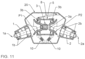
- FIG. 11 is a lateral view of a transmission including springs, according to an embodiment of the present invention.
- the present invention can be implemented according to multiple alternative construction arrangements, which appear with different geometric designs, but which realize the same type of operation.
- a continuously variable transmission comprises a first and a second main shaft 1 , 2 , having respective rotation axes 1 a , 2 a fixed and coplanar with respect to a reference plane P.
- Said main shafts 1 , 2 are each provided with a primary roll surface 13 , 23 shaped as a solid of revolution.
- the transmission further comprises at least one auxiliary shaft 3 (which in turn can be formed by a plurality of secondary shafts 3 ′, 3 ′′, as shown by way of example in FIGS. 7 A through 9 B ) rotatable around an axis of rotation 3 a and interposed between the main shafts 1 , 2 .
- the auxiliary shaft 3 is provided with two secondary roll surfaces 31 , 32 , each shaped as a solid of revolution and each placed in contact with a respective primary roll surface 13 , 23 of the main shafts 1 , 2 , so as to transmit the motion of a main shaft to the other main shaft.
- the rotation axis 3 a of the auxiliary shaft 3 is movable only along the reference plane P identified by the rotation axes 1 a , 2 a of the two main shafts 1 , 2 .
- the roll surfaces 13 , 23 , 31 , 32 are so shaped that, in the reference plane P, the line TG 1 tangent to the primary roll surface 13 of the first main shaft 1 and to the corresponding secondary roll surface 31 of the auxiliary shaft 3 in the contact point P 1 between said roll surfaces 13 , 31 always passes through the intersection point T 1 between the rotation axis 1 a of said first main shaft 1 and the rotation axis 3 a of said auxiliary shaft 3 .
- intersection point T 1 between the rotation axis 1 a of the first main shaft 1 and the rotation axis 3 a of the auxiliary shaft 3 is distinct from the intersection point T 2 between the rotation axis 2 a of the second main shaft 2 and the rotation axis 3 a of said auxiliary shaft 3 .
- All embodiments of the present invention have in common the properties illustrated above, i.e. that in the reference plane P the straight line tangent to the roll surface in the contact point always passes through the intersection point of the axes of the shafts that participate in the contact, and that the intersection between the rotation axis of the auxiliary shaft and, respectively, the rotation axes of the first and of the second main shaft takes place in two distinct points.
- the secondary roll surfaces 31 , 32 of the auxiliary shaft 3 roll without rubbing and without any prying motion on the respective primary roll surfaces 13 , 23 of the main shafts 1 , 2 .
- the geometric loci of the points that meet the above condition identify on the reference plane P the generatrix curves of the roll surfaces 13 , 23 , 31 , 32 .
- the profile of the generatrix curves of the roll surfaces 13 , 23 , 31 , 32 can be drawn, with as precise an approximation as is desired, by means of the iterative process described below.
- the process can be carried out graphically or with an analytical numeric calculation.
- the first step of the iterative process consists of providing an auxiliary shaft 3 provided with two secondary roll surfaces 31 , 32 , each shaped as a solid of revolution and provided with double curvature.
- the reference numbers in the figures are flanked by a letter identifying the iteration (in the illustrated example, the letter “A” for the first iteration, “B” for the second, etc.).
- the reference 3 A indicates the position of the auxiliary shaft 3 in the first iteration.
- the straight line TG 1 A is drawn, which passes through the point T 1 A of intersection of the rotation axes 1 a and 3 a A (respectively of the first main shaft 1 , not shown, and of the auxiliary shaft 3 A) and tangential to the profile 31 A, which represents the generatrix curve of the secondary roll surface associated to the auxiliary shaft 3 A.
- the straight line TG 2 A is drawn, which passes through the point T 2 A of intersection of the rotation axes 2 a and 3 a A (respectively of the second main shaft 2 , not shown, and of the auxiliary shaft 3 A) and tangential to the profile 32 A, which represents the generatrix curve of the secondary roll surface at the opposite end of the auxiliary shaft 3 A.
- the two initial contact points P 1 A and P 2 A are then identified, in the two points of tangency.
- the point A of intersection between the two straight lines R 1 A and R 2 A is the center of rotation of the first cycle of the iterative process.
- a small rotation around the point A is imposed on the shaft 3 A, thereby bringing it to the position 3 B (second iteration).
- the size of the rotation to be adopted for each iteration is the smaller, the higher the desired precision of the result.
- the point T 1 B of intersection is identified between the rotation axis 1 a of the first main shaft 1 (not shown) and the rotation axis 3 a B of the auxiliary shaft 3 B (i.e. the axis of the auxiliary shaft 3 in the second iteration).
- the point T 2 B of intersection is identified between the rotation axis 2 a of the second main shaft 2 (not shown) and the rotation axis 3 a B of the auxiliary shaft 3 B.
- FIG. 2 C shows a series of line segments, each positioned in one of the points P 1 A, P 1 B, P 1 C and P 2 A, P 2 B, P 2 C and each inclined like the respective tangent.
- the corresponding generatrix curve is obtained by joining the segments.
- the profile of the primary roll surfaces 13 , 23 is drawn, with approximation as precise as is desired, by means of a succession of rotations, as small as desired, around a continuously variable point (center of instantaneous rotation) given by the intersection between the two straight lines R 1 and R 2 , each perpendicular respectively to one of the tangent straight lines TG 1 and TG 2 in the contact points P 1 and P 2 .
- a continuously variable point center of instantaneous rotation
- the result can be optimized varying the profile of the generatrix curves of the secondary roll surfaces 31 , 32 of the auxiliary shaft 3 and varying the mutual initial position of the shafts 1 , 2 , 3 .
- the radius of curvature of the generatrix curves of the secondary roll surfaces 31 , 32 of the auxiliary shaft 3 , lying on the reference plane P is variable along said generatrix curves, to reduce stresses in the contact points.
- FIGS. 1 A and 1 B were set as the basis for the above description because these figures are clearer depictions.
- the main shafts 1 , 2 can be arranged so that the rotation axis 1 a of one of the main shafts 1 intersects in one point the rotation axis 2 a of the other main shaft 2 (in a configuration in which said rotation axes 1 a , 2 a are mutually incident, as shown by way of example in the figures from 1 A to 3 B), or said main shafts 1 , 2 can be positioned so that the respective rotation axes 1 a , 2 a are mutually parallel or coincident (as shown by way of example in figures from 4 A to 8 B).
- the auxiliary shaft 3 can be made in a single piece or, as shown by way of example in the figures from 7 A to 9 B, it can comprise two secondary shafts 3 ′, 3 ′′ connected to each other by an engagement member 14 (advantageously, a gear) adapted to constrain said secondary shafts 3 ′, 3 ′′ to maintain a constant ratio between the respective rotational speeds.
- an engagement member 14 advantageousously, a gear
- a similar configuration is particularly advantageous when the two main shafts 1 , 2 are mutually coaxial (as in the figures from 7 A to 9 B).
- Each of the two secondary shafts 3 ′, 3 ′′ brings to a first end a respective secondary roll surface 31 , 32 , while the opposite ends will be configured so as to allow connection with the other secondary shaft 3 ′, 3 ′′ (for example, a first secondary shaft may have a gear portion that cooperates with a complementary gear portion borne by the second secondary shaft, for example as shown in the figures from 7 A to 9 B).
- the secondary shafts 3 ′, 3 ′′ can be coaxial, or they can be rotatable around respective mutually offset rotation axes 3 ′ a , 3 ′′ a (for example in the figures from 7 A to 9 B). In this latter case, what is stated above with reference to the rotation axes 3 a of the auxiliary shaft 3 applies in a similar way to the rotation axes 3 ′ a , 3 ′′ a of the secondary shafts 3 ′, 3 ′′.
- the auxiliary shaft 3 (or the secondary shafts 3 ′, 3 ′′) can be of the male type or of the female type.
- the secondary roll surfaces 31 , 32 are arranged in such a way that the contact point with the respective primary roll surfaces 13 , 23 faces toward the rotation axis of the auxiliary shaft 3 , while in the male type it faces outward.
- auxiliary shafts 3 of the female type is particularly favorable because it allows to reduce pressure between the surfaces in the contact zone.
- the configuration can be symmetrical or asymmetrical, in the sense that the primary roll surfaces 13 , 23 can have equal and mutually specular shapes and concurrently also the secondary roll surfaces 31 , 32 can have equal and mutually specular shapes (symmetrical drawing), or all primary and secondary roll surfaces 13 , 23 , 31 , 32 can have mutually different shapes (asymmetrical drawing).
- the asymmetrical construction arrangement is presented in FIGS. 5 A and 5 B (which, aside from said feature, is otherwise similar to the arrangement of FIGS. 4 A and 4 B , both having parallel main shafts and male auxiliary shaft). In any case, all construction arrangements presented herein can be implemented both in symmetrical and asymmetrical form.
- the transmission ratio varies between a maximum value and a minimum value, which are one the reciprocal of the other. In this case, when the auxiliary shaft 3 is in the central position, the transmission ratio is equal to 1.
- the configurations that have the female auxiliary shaft also have the advantage that the latter, having a roll circle with greater diameter than that of the drive shaft, has lower speed of rotation than the drive shaft itself. This feature is favorable for the dimensioning of the bearings that support the auxiliary shaft 3 .
Landscapes
- Engineering & Computer Science (AREA)
- General Engineering & Computer Science (AREA)
- Mechanical Engineering (AREA)
- Friction Gearing (AREA)
- Polysaccharides And Polysaccharide Derivatives (AREA)
- Investigation Of Foundation Soil And Reinforcement Of Foundation Soil By Compacting Or Drainage (AREA)
- Separation By Low-Temperature Treatments (AREA)
Abstract
Description
-
- the curves must join respectively the contact points P1A, P1B, P1C, etc. for the primary roll surface 13 (associated with the first main shaft 1), and P2A, P2B, P2C, etc. for the primary roll surface 23 (associated with the second main shaft 2).
-
- in the figures from 1A to 1B, from 6A to 7B and from 9A to 9B, the
main shafts auxiliary shaft 3 is in the male configuration; - in the figures from 3A to 3B, from 8A to 8B and from 10A to 10B, the
main shafts auxiliary shaft 3 is in the female configuration; and - in the figures from 4A to 5B, both the
main shafts auxiliary shaft 3 are in the male configuration.
- in the figures from 1A to 1B, from 6A to 7B and from 9A to 9B, the
Claims (13)
Applications Claiming Priority (3)
| Application Number | Priority Date | Filing Date | Title |
|---|---|---|---|
| IT102018000009270A IT201800009270A1 (en) | 2018-10-09 | 2018-10-09 | Continuous change. |
| IT102018000009270 | 2018-10-09 | ||
| PCT/IB2019/058584 WO2020075078A1 (en) | 2018-10-09 | 2019-10-09 | Continuously variable transmission |
Publications (2)
| Publication Number | Publication Date |
|---|---|
| US20210388886A1 US20210388886A1 (en) | 2021-12-16 |
| US12110947B2 true US12110947B2 (en) | 2024-10-08 |
Family
ID=64902248
Family Applications (1)
| Application Number | Title | Priority Date | Filing Date |
|---|---|---|---|
| US17/283,923 Active US12110947B2 (en) | 2018-10-09 | 2019-10-09 | Continuously variable transmission |
Country Status (7)
| Country | Link |
|---|---|
| US (1) | US12110947B2 (en) |
| EP (1) | EP3864320B1 (en) |
| JP (1) | JP7691366B2 (en) |
| KR (1) | KR102837288B1 (en) |
| CN (1) | CN113167363B (en) |
| IT (1) | IT201800009270A1 (en) |
| WO (1) | WO2020075078A1 (en) |
Families Citing this family (1)
| Publication number | Priority date | Publication date | Assignee | Title |
|---|---|---|---|---|
| JP2025025413A (en) * | 2023-08-09 | 2025-02-21 | 住友重機械工業株式会社 | Friction Transmission Device |
Citations (7)
| Publication number | Priority date | Publication date | Assignee | Title |
|---|---|---|---|---|
| US2734389A (en) * | 1956-02-14 | Strecker | ||
| US2786363A (en) * | 1955-05-31 | 1957-03-26 | Gen Motors Corp | Torus ring for infinitely variable transmission |
| US3242748A (en) * | 1963-02-04 | 1966-03-29 | Prager Peter-Conrad | Friction gear |
| US3261220A (en) | 1962-04-25 | 1966-07-19 | Excelermatic | Motion transmitting device |
| DE2457060A1 (en) | 1974-12-03 | 1976-07-15 | Titt Geb Gundel Lore | Infinitely variable friction gearing - has drive members with confronting hemispherical recesses engaged by friction wheels |
| DE102006039319A1 (en) | 2006-08-22 | 2008-02-28 | Stephan Horsthemke | Stepless friction gear for vehicles, particularly small car class, has function designed as centrifugal mass according to available output-sided universal ball, for energy storage, which is used for increasing accelerating power |
| CN107339384A (en) * | 2016-10-31 | 2017-11-10 | 西华大学 | One kind is without spin integral curve formula variable speed unit |
Family Cites Families (7)
| Publication number | Priority date | Publication date | Assignee | Title |
|---|---|---|---|---|
| DE2942076A1 (en) * | 1979-10-18 | 1981-04-30 | Detlef 7531 Kieselbronn Hofmann | CONTINUOUSLY ADJUSTABLE GEARBOX |
| EP1045999B1 (en) * | 1998-01-12 | 2003-10-08 | Orbital Traction Limited | A continuously variable transmission device |
| IL128677A0 (en) * | 1999-02-23 | 2000-01-31 | Siman Tov Ran | Continuous variable transmission |
| CN102725561B (en) * | 2009-10-08 | 2015-03-25 | 终极变速器私人有限公司 | Full toroidal traction drive |
| WO2014117167A1 (en) * | 2013-01-28 | 2014-07-31 | Robert Hornblower Meyer | Continuously variable drive mechanism |
| CN103174808A (en) * | 2013-03-13 | 2013-06-26 | 山东交通学院 | Stepless speed change device |
| JP7233354B2 (en) * | 2019-11-12 | 2023-03-06 | 三菱電機株式会社 | Display unit manufacturing method and display device manufacturing method |
-
2018
- 2018-10-09 IT IT102018000009270A patent/IT201800009270A1/en unknown
-
2019
- 2019-10-09 CN CN201980081418.0A patent/CN113167363B/en active Active
- 2019-10-09 WO PCT/IB2019/058584 patent/WO2020075078A1/en not_active Ceased
- 2019-10-09 KR KR1020217013749A patent/KR102837288B1/en active Active
- 2019-10-09 EP EP19801098.5A patent/EP3864320B1/en active Active
- 2019-10-09 JP JP2021544958A patent/JP7691366B2/en active Active
- 2019-10-09 US US17/283,923 patent/US12110947B2/en active Active
Patent Citations (7)
| Publication number | Priority date | Publication date | Assignee | Title |
|---|---|---|---|---|
| US2734389A (en) * | 1956-02-14 | Strecker | ||
| US2786363A (en) * | 1955-05-31 | 1957-03-26 | Gen Motors Corp | Torus ring for infinitely variable transmission |
| US3261220A (en) | 1962-04-25 | 1966-07-19 | Excelermatic | Motion transmitting device |
| US3242748A (en) * | 1963-02-04 | 1966-03-29 | Prager Peter-Conrad | Friction gear |
| DE2457060A1 (en) | 1974-12-03 | 1976-07-15 | Titt Geb Gundel Lore | Infinitely variable friction gearing - has drive members with confronting hemispherical recesses engaged by friction wheels |
| DE102006039319A1 (en) | 2006-08-22 | 2008-02-28 | Stephan Horsthemke | Stepless friction gear for vehicles, particularly small car class, has function designed as centrifugal mass according to available output-sided universal ball, for energy storage, which is used for increasing accelerating power |
| CN107339384A (en) * | 2016-10-31 | 2017-11-10 | 西华大学 | One kind is without spin integral curve formula variable speed unit |
Non-Patent Citations (3)
| Title |
|---|
| English translation of CN 107339384 to Li, published Nov. 2017. * |
| International Search Report, issued in PCT/IB2019/058584, mailed Dec. 4, 2019, Rijswijk, Netherlands. |
| Written Opinion, issued in PCT/IB2019/058584, mailed Dec. 4, 2019, Rijswijk, Netherlands. |
Also Published As
| Publication number | Publication date |
|---|---|
| CN113167363B (en) | 2024-09-10 |
| WO2020075078A1 (en) | 2020-04-16 |
| JP2022508673A (en) | 2022-01-19 |
| IT201800009270A1 (en) | 2020-04-09 |
| US20210388886A1 (en) | 2021-12-16 |
| KR102837288B1 (en) | 2025-07-21 |
| EP3864320A1 (en) | 2021-08-18 |
| KR20210088573A (en) | 2021-07-14 |
| EP3864320B1 (en) | 2022-08-24 |
| JP7691366B2 (en) | 2025-06-11 |
| CN113167363A (en) | 2021-07-23 |
Similar Documents
| Publication | Publication Date | Title |
|---|---|---|
| CN102725561B (en) | Full toroidal traction drive | |
| RU2382917C2 (en) | Device for infinitely variable control of reduction ratio (variator) | |
| US12110947B2 (en) | Continuously variable transmission | |
| US10221925B2 (en) | Conical pulley for belt CVT | |
| CN114483898B (en) | Speed regulating device of stepless speed changer | |
| CN111692306B (en) | Rolling type stepless speed changer | |
| US4682517A (en) | Variable speed drive--apparatus and method of fabricating the apparatus | |
| US10378621B2 (en) | Continuously variable transmission | |
| CN202418458U (en) | Stepless speed reducer with friction-pair planetary transmission | |
| CN105276110A (en) | Self-rotation-free traction type stepless speed changer | |
| CN102252075A (en) | Friction pair planet driven continuously variable transmission | |
| CN102483044B (en) | CVT | |
| CN203868263U (en) | Stepless speed change device | |
| CN203627699U (en) | Roller cone plate type stepless speed variator | |
| CN112377583A (en) | Steel ball cone pulley type stepless speed changer | |
| RU2160400C2 (en) | Torque transformer | |
| JP3461876B2 (en) | Inverter continuously variable transmission | |
| WO2005083299A2 (en) | Continuously variable transmission with easily changeable transmission ratio | |
| CN105697702B (en) | Buncher | |
| CN110005773A (en) | A kind of steel ball stepless speed changer | |
| CN1141501C (en) | Stepless speed variator | |
| KR20190057023A (en) | Continuously variable transmission | |
| US9371893B2 (en) | Contoured radius continuously variable transmission | |
| RU2553529C1 (en) | Chain variator with automatically changed pitch | |
| JP2017031994A (en) | Continuously variable transmission |
Legal Events
| Date | Code | Title | Description |
|---|---|---|---|
| FEPP | Fee payment procedure |
Free format text: ENTITY STATUS SET TO UNDISCOUNTED (ORIGINAL EVENT CODE: BIG.); ENTITY STATUS OF PATENT OWNER: SMALL ENTITY |
|
| FEPP | Fee payment procedure |
Free format text: ENTITY STATUS SET TO SMALL (ORIGINAL EVENT CODE: SMAL); ENTITY STATUS OF PATENT OWNER: SMALL ENTITY |
|
| AS | Assignment |
Owner name: ELTAT S.R.L., ITALY Free format text: ASSIGNMENT OF ASSIGNORS INTEREST;ASSIGNORS:CHIAVES, CARLO;CHIAVES, PAOLO;REEL/FRAME:056626/0063 Effective date: 20210525 |
|
| STPP | Information on status: patent application and granting procedure in general |
Free format text: DOCKETED NEW CASE - READY FOR EXAMINATION |
|
| STPP | Information on status: patent application and granting procedure in general |
Free format text: NON FINAL ACTION MAILED |
|
| STPP | Information on status: patent application and granting procedure in general |
Free format text: FINAL REJECTION MAILED |
|
| STPP | Information on status: patent application and granting procedure in general |
Free format text: DOCKETED NEW CASE - READY FOR EXAMINATION |
|
| STPP | Information on status: patent application and granting procedure in general |
Free format text: NON FINAL ACTION MAILED |
|
| STPP | Information on status: patent application and granting procedure in general |
Free format text: RESPONSE TO NON-FINAL OFFICE ACTION ENTERED AND FORWARDED TO EXAMINER |
|
| STPP | Information on status: patent application and granting procedure in general |
Free format text: NOTICE OF ALLOWANCE MAILED -- APPLICATION RECEIVED IN OFFICE OF PUBLICATIONS |
|
| STPP | Information on status: patent application and granting procedure in general |
Free format text: PUBLICATIONS -- ISSUE FEE PAYMENT VERIFIED |
|
| STCF | Information on status: patent grant |
Free format text: PATENTED CASE |