US12096949B2 - Device for the treatment of tissue calcification - Google Patents
Device for the treatment of tissue calcification Download PDFInfo
- Publication number
- US12096949B2 US12096949B2 US17/418,874 US202017418874A US12096949B2 US 12096949 B2 US12096949 B2 US 12096949B2 US 202017418874 A US202017418874 A US 202017418874A US 12096949 B2 US12096949 B2 US 12096949B2
- Authority
- US
- United States
- Prior art keywords
- treatment
- frequencies
- ultrasound
- khz
- mhz
- Prior art date
- Legal status (The legal status is an assumption and is not a legal conclusion. Google has not performed a legal analysis and makes no representation as to the accuracy of the status listed.)
- Active, expires
Links
Images


Classifications
-
- A—HUMAN NECESSITIES
- A61—MEDICAL OR VETERINARY SCIENCE; HYGIENE
- A61B—DIAGNOSIS; SURGERY; IDENTIFICATION
- A61B17/00—Surgical instruments, devices or methods
- A61B17/22—Implements for squeezing-off ulcers or the like on inner organs of the body; Implements for scraping-out cavities of body organs, e.g. bones; for invasive removal or destruction of calculus using mechanical vibrations; for removing obstructions in blood vessels, not otherwise provided for
- A61B17/22004—Implements for squeezing-off ulcers or the like on inner organs of the body; Implements for scraping-out cavities of body organs, e.g. bones; for invasive removal or destruction of calculus using mechanical vibrations; for removing obstructions in blood vessels, not otherwise provided for using mechanical vibrations, e.g. ultrasonic shock waves
- A61B17/22012—Implements for squeezing-off ulcers or the like on inner organs of the body; Implements for scraping-out cavities of body organs, e.g. bones; for invasive removal or destruction of calculus using mechanical vibrations; for removing obstructions in blood vessels, not otherwise provided for using mechanical vibrations, e.g. ultrasonic shock waves in direct contact with, or very close to, the obstruction or concrement
- A61B17/2202—Implements for squeezing-off ulcers or the like on inner organs of the body; Implements for scraping-out cavities of body organs, e.g. bones; for invasive removal or destruction of calculus using mechanical vibrations; for removing obstructions in blood vessels, not otherwise provided for using mechanical vibrations, e.g. ultrasonic shock waves in direct contact with, or very close to, the obstruction or concrement the ultrasound transducer being inside patient's body at the distal end of the catheter
-
- A—HUMAN NECESSITIES
- A61—MEDICAL OR VETERINARY SCIENCE; HYGIENE
- A61B—DIAGNOSIS; SURGERY; IDENTIFICATION
- A61B17/00—Surgical instruments, devices or methods
- A61B17/22—Implements for squeezing-off ulcers or the like on inner organs of the body; Implements for scraping-out cavities of body organs, e.g. bones; for invasive removal or destruction of calculus using mechanical vibrations; for removing obstructions in blood vessels, not otherwise provided for
- A61B17/22004—Implements for squeezing-off ulcers or the like on inner organs of the body; Implements for scraping-out cavities of body organs, e.g. bones; for invasive removal or destruction of calculus using mechanical vibrations; for removing obstructions in blood vessels, not otherwise provided for using mechanical vibrations, e.g. ultrasonic shock waves
- A61B2017/22005—Effects, e.g. on tissue
- A61B2017/22007—Cavitation or pseudocavitation, i.e. creation of gas bubbles generating a secondary shock wave when collapsing
- A61B2017/22008—Cavitation or pseudocavitation, i.e. creation of gas bubbles generating a secondary shock wave when collapsing used or promoted
-
- A—HUMAN NECESSITIES
- A61—MEDICAL OR VETERINARY SCIENCE; HYGIENE
- A61B—DIAGNOSIS; SURGERY; IDENTIFICATION
- A61B17/00—Surgical instruments, devices or methods
- A61B17/22—Implements for squeezing-off ulcers or the like on inner organs of the body; Implements for scraping-out cavities of body organs, e.g. bones; for invasive removal or destruction of calculus using mechanical vibrations; for removing obstructions in blood vessels, not otherwise provided for
- A61B17/22004—Implements for squeezing-off ulcers or the like on inner organs of the body; Implements for scraping-out cavities of body organs, e.g. bones; for invasive removal or destruction of calculus using mechanical vibrations; for removing obstructions in blood vessels, not otherwise provided for using mechanical vibrations, e.g. ultrasonic shock waves
- A61B17/22012—Implements for squeezing-off ulcers or the like on inner organs of the body; Implements for scraping-out cavities of body organs, e.g. bones; for invasive removal or destruction of calculus using mechanical vibrations; for removing obstructions in blood vessels, not otherwise provided for using mechanical vibrations, e.g. ultrasonic shock waves in direct contact with, or very close to, the obstruction or concrement
- A61B2017/22025—Implements for squeezing-off ulcers or the like on inner organs of the body; Implements for scraping-out cavities of body organs, e.g. bones; for invasive removal or destruction of calculus using mechanical vibrations; for removing obstructions in blood vessels, not otherwise provided for using mechanical vibrations, e.g. ultrasonic shock waves in direct contact with, or very close to, the obstruction or concrement applying a shock wave
-
- A—HUMAN NECESSITIES
- A61—MEDICAL OR VETERINARY SCIENCE; HYGIENE
- A61B—DIAGNOSIS; SURGERY; IDENTIFICATION
- A61B17/00—Surgical instruments, devices or methods
- A61B17/22—Implements for squeezing-off ulcers or the like on inner organs of the body; Implements for scraping-out cavities of body organs, e.g. bones; for invasive removal or destruction of calculus using mechanical vibrations; for removing obstructions in blood vessels, not otherwise provided for
- A61B17/22004—Implements for squeezing-off ulcers or the like on inner organs of the body; Implements for scraping-out cavities of body organs, e.g. bones; for invasive removal or destruction of calculus using mechanical vibrations; for removing obstructions in blood vessels, not otherwise provided for using mechanical vibrations, e.g. ultrasonic shock waves
- A61B2017/22027—Features of transducers
- A61B2017/22028—Features of transducers arrays, e.g. phased arrays
-
- A—HUMAN NECESSITIES
- A61—MEDICAL OR VETERINARY SCIENCE; HYGIENE
- A61B—DIAGNOSIS; SURGERY; IDENTIFICATION
- A61B17/00—Surgical instruments, devices or methods
- A61B17/22—Implements for squeezing-off ulcers or the like on inner organs of the body; Implements for scraping-out cavities of body organs, e.g. bones; for invasive removal or destruction of calculus using mechanical vibrations; for removing obstructions in blood vessels, not otherwise provided for
- A61B2017/22079—Implements for squeezing-off ulcers or the like on inner organs of the body; Implements for scraping-out cavities of body organs, e.g. bones; for invasive removal or destruction of calculus using mechanical vibrations; for removing obstructions in blood vessels, not otherwise provided for with suction of debris
-
- A—HUMAN NECESSITIES
- A61—MEDICAL OR VETERINARY SCIENCE; HYGIENE
- A61B—DIAGNOSIS; SURGERY; IDENTIFICATION
- A61B17/00—Surgical instruments, devices or methods
- A61B17/22—Implements for squeezing-off ulcers or the like on inner organs of the body; Implements for scraping-out cavities of body organs, e.g. bones; for invasive removal or destruction of calculus using mechanical vibrations; for removing obstructions in blood vessels, not otherwise provided for
- A61B2017/22098—Decalcification of valves
-
- A—HUMAN NECESSITIES
- A61—MEDICAL OR VETERINARY SCIENCE; HYGIENE
- A61N—ELECTROTHERAPY; MAGNETOTHERAPY; RADIATION THERAPY; ULTRASOUND THERAPY
- A61N7/00—Ultrasound therapy
- A61N2007/0039—Ultrasound therapy using microbubbles
-
- A—HUMAN NECESSITIES
- A61—MEDICAL OR VETERINARY SCIENCE; HYGIENE
- A61N—ELECTROTHERAPY; MAGNETOTHERAPY; RADIATION THERAPY; ULTRASOUND THERAPY
- A61N7/00—Ultrasound therapy
- A61N2007/0073—Ultrasound therapy using multiple frequencies
Definitions
- the present invention generally relates to the treatment of tissue calcification, in particular to the treatment of aortic leaflet calcification.
- Tissue calcifications due to inflammatory conditions and specific biological processes, are common after 60 years of age.
- Some disorders can cause calcium to deposit in ligaments, tendons, blood vessels, organs, particularly in the heart, in the mitral annulus or in the aortic leaflets, thereby altering their physiological functions.
- valvular aortic degenerative stenosis typical of advanced age, has a prevalence of 3% in the Mediterranean area alone (4.6% for age >74 years) and reaches 10% in America and North America. According to Carabello, 2009, the prevalence of a clinically significant stenotic condition is about 20% in patients in the 65-75 age group, about 35% in the 75-85 age group and 48% in 85-percent patients.
- Valvular calcification is the gradual accumulation of calcium and phosphate minerals: deposits that can thicken and form mineralized nodules. Deposits are concentrated in the areas most subjected to mechanical stress. It follows an impairment of cardiac hemodynamic. The pathogenesis of cardiac valvular calcifications is the result of a chronic inflammatory process.
- the area of the aortic valve orifice should be reduced to less than 1 ⁇ 4 of its normal size before significant hemodynamic changes occur. Starting from the onset of symptoms, the average survival can be as low as 2-3 years.
- calcified aortic stenosis is, when possible, treated by surgery or trans-catheter TAVI, replacing the damaged valve with a valve prosthesis.
- surgery may be particularly risky, due to the patient's particular condition (for example, advanced age and other co-morbidities).
- TAVI transcatheter procedure
- Ultrasonic waves in particular shock waves, are daily used to treat calcifications in urological or orthopaedic fields and, to a less extend, in the vascular or cardiological field.
- An example of such a treatment in an implanted structure, such as a heart valve, is disclosed in U.S. Pat. No. 8,083,707 B2.
- the present invention relates to a device and method that provide an improved tissue calcification treatment with respect to existing devices and methods.
- the device according to the invention comprises a first ultrasound emission source that is adapted to provide ultrasound waves with MHz frequencies and a second ultrasound emission source that is adapted to provide ultrasound waves with KHz frequencies, both MHz and KHz waves being used for the treatment of tissue calcification.
- the amplitude of one or all ultrasound emission sources can be varied, independently from each other, or in coordination.
- the method according to the invention comprises the simultaneous use of ultrasound waves with MHz frequencies and ultrasound waves with KHz frequencies.
- the MHz frequency is preferably selected between 3 and 4 MHz and the KHz frequency being preferably in the order of 100 KHz.
- the expression “ultrasonic wave” has to be understood in its broadest definition. It includes any sound wave with a frequency above the upper audible limit of human hearing, usually in the order of 20 KHz.
- the ultrasonic wave used in the present invention may be generated in a continuous or discontinuous manner, e.g. by pulses.
- the two frequencies are in opposite directions with respect to the calcified zone.
- More than two ultrasound emission sources can be used in the present invention, in any suitable geometry and/or configuration.
- the ultrasound emission sources are configured in a phased array.
- each single emission source phase shifting
- an interference is obtained between the single ultrasound fields generated, which leads to a focusing at a specific depth and specific angle.
- the time delays appropriately, the focus area of the ultrasound field can be changed to the treatment, sweeping the beam on the leaflet.
- the device When used for the treatment of an aortic valve, the device is preferably introduced by a catheter, designed for access via a femoral artery, into the seat of the aortic valve.
- the combined and simultaneous use of MHz and KHz frequencies induce an efficient fragmentation of the calcium deposits in the aortic valve leaflets.
- the device preferably comprises an antiembolic filter to capture any debris resulting from the decalcification treatment.
- the device according to the invention provides several advantages, such as:
- FIG. 1 First structure of a device according to the invention placed in the sinus of valve for the treatment of the aortic side of valve's leaflets and the combination with the low frequency field
- FIG. 2 view of the first structure of FIG. 1 with evidence of the 6 arms on which the piezoelectric transducers are mounted
- FIG. 3 Siliconed structure positioned in the native aortic valve seat for the treatment of ventricular side of the valvular leaflets.
- the pillars keep the valve open.
- the piezoelectric transducers are mounted on the pillars for the creation of the low frequency ultrasonic “counter-field”.
- FIG. 4 Assembly view of first and second structures: the leaflets will be held back between the arms of the two structures.
- FIG. 5 Block components diagram of the device
- FIG. 6 Piezoelectric transducer equivalent circuit-Impedance diagram
- FIG. 7 Pulse wave to power the piezoelectric transducers
- FIG. 8 CT evidences of the treatment with ultrasound pulse waves: for reference see the fractures on the “Post” picture.
- FIG. 10 First embodiment representation: the device is opened and positioned in the native valve with the valvular leaflets held back by the two “active” structures on which the piezoelectric transducers are “housed”. In grey the artificial valve.
- FIG. 11 The second embodiment with the ablator and its delivery system
- FIG. 12 Third embodiment ablator
- FIG. 13 Apfel, Holland, 1991 chart for 3 different frequencies. “Peak negative pressure threshold vs initial bubble radius”.
- FIG. 14 Example according to the invention of a double support for the piezoelectric transducer called “bunk structure”
- FIG. 15 Deployment with temporary artificial valve placed inside the patient's native aortic valve with two transducers placed on extrados side of the valve leaflets
- FIG. 16 Signal composed of pulse sequences at two different frequencies
- FIG. 17 Deployment with temporary artificial valve placed inside the patient's native aortic valve with a single transducer placed on extrados side of the valve leaflets
- FIG. 18 Example with deflector (in grey) anchored to the support structure
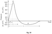
- FIG. 19 “Shockwave pulse” from ResearchGate, C. Schmitz et al.
- the device called “ablator” consists of three elements ( FIG. 5 ):
- the pulse generator can generate two impulsive signals simultaneously, in the range of 20-100V, with a positive peak followed by a negative peak, ( FIG. 7 ), at 2 frequencies, one around 100 KHz and the second one in unit of MHz.
- Unit 2 and 3 are conceived to be entirely collapsed inside a catheter and introduced in the patient's artery with the aim to reach the sinus of the valve and the valve itself and to be deployed in place.
- the emission unit of the ultrasound field comprises two structures.
- the first structure 1 ( FIG. 1 ) consists of multiple nitinol or steel arms 3 and is introduced through a femoral catheter, open and placed in the sinus of the valve.
- the piezoelectric transducers 4 are electrically connected in parallel to reduce the total impedance and increase the current circulating at the same supply voltage.
- the shape of the arms 3 of this structure 1 has a bell section to adapt to the variability of the leaflets of the valve 8 opened, during treatment, from the second structure 2 ( FIG. 3 ).
- At least 6 arms 3 are necessary to treat simultaneously leaflets and commissures of the aortic valve.
- Three arms 3 with their piezoelectric transducers 4 are adapted to treat the leaflets creating the ultrasound counter-field opposite to the field generated by the second structure.
- the other arms 3 are devoted to treat the inter-leaflet triangle.
- the second structure 2 integrates both the ablation function, with piezoelectric transducers 5 to generate the impulsive ultrasound waves, and the replacement valve function: positioned in the aortic valve seat, it keeps the leaflets 8 open with some pillars on which the piezoelectric crystals are positioned for treatment of the ventricular side of the valvular leaflets and for the creation of the low frequency ultrasonic “counter-field”, in the order of thousands of Hz (e.g. 20 KHz or 100 KHz).
- the second structure 2 provides an artificial valve 6 during the decalcifying treatment of the leaflets 8 of the native valve, kept open during operation.
- the valve is made of leak-free coated fabric, for instance as disclosed in patent document PCT/IB2018/056553.
- the device includes a “basket-shaped” filter 7 able to collect the debris produced by the disruption procedure of calcium deposits.
- the valve seat is reached: the first 6 -arm structure 1 is introduced into the sinus of the valve and opened.
- the second structure 2 follows and is placed in the native valve seat, opening the valve leaflets 8 .
- the valvular leaflets 8 are thus held back by the two structures 1 , 2 .
- the ultrasonic field emitted by electrically powered transducers 4 , 5 connected to the pulse generator, performs the decalcification treatment.
- the temperature is controlled by means of a thermocouple which supplies feedback to the pulse generator, which can interrupt the power supply of the transducers and consequently the therapeutic ultrasonic field.
- the ultrasound emission unit comprises three structures ( FIG. 11 ):
- This solution allows to treat a commissure and the two adjacent valve leaflets for each session, acting in particular on the nadirs of the semi-lunar leaflet attachment, without blocking the function of the cardiac valve.
- this embodiment can include a “basket-shaped” filter 7 able to collect the debris produced by the disruption procedure of calcium deposits.
- a third embodiment derived from the second embodiment, there is only one “petal” structure 10 with several piezoelectric transducers housed, for the treatment of one aortic valve leaflet 8 and one arm of the support with one or more piezoelectric transducer, for the treatment of one commissure ( FIG. 12 ).
- the ultrasonic field obtained by the combination of at least two frequencies, one in the order of 2-4 MHz and the second in the order of 100 KHz, is generated by two piezoelectric transducers positioned both on the extrados side of the aortic valve leaflet to be treated, placed side by side between them in parallel.
- a combination of transducers and structural elements produces ultrasonic waves that interact with each other.
- the ultrasonic field is modulated by the combination of the two frequencies with “constructive” effects, ie the sum of the contributions.
- a double layer structure called “bunk structure” is built.
- a possible realization has the shape represented in FIG. 14 .
- the “bunk structure” is preferably made of steel or titanium.
- the transducer operating at a frequency of 100 KHz (+20 KHz) is housed in the lower base ( 13 ), while the second transducer operating at a frequency of 2-4 MHz is housed in the upper base ( 12 ).
- a free space is left between the lower and upper transducers, at least twice the variation of the transducer length due to piezoelectric effect (usually the variation can be a small percentage, ie. between 0.1% and 0.15% of the size of the transducer.
- the distance is for instance 0.3 mm).
- the electrical insulation of the transducers can be carried out by depositing a dielectric coating (e.g. Parylene) on the “bunk structure”, with subsequent deposit of insulating coating on the whole assembled structure.
- a dielectric coating e.g. Parylene
- the electrical connection of the transducers takes place via enamelled copper wire soldered to the conductive armature of the transducers.
- the flexible circuit can include small conductive areas to electrically connect the transducer.
- This embodiment also includes an artificial temporary valve.
- the FIG. 15 shows the deployment with temporary artificial valve placed inside the patient's native aortic valve.
- the transducer supports (called ablation units) are positioned on the extrados side of the valve lealfets.
- the FIG. 15 only one ablation unit is shown in the image, but the system can use 2 or 3 pairs of ablation units, for the simultaneous treatment of 2 or 3 leaflets. In this embodiment there are no transducers attached to the valve structure.
- the ultrasonic field is generated by a single piezoelectric transducer supplied with the two electrical signals at the two different frequencies, 100 KHz and 2-4 MHz, applied in sequence.
- a short pause t 2 of a few milliseconds and however less than 1 second (i.e. 1 s or 500 ms or also a few milliseconds) between the two trains of impulses can be optionally considered to allow the transducer to reduce the oscillation before applying the different frequency.
- a structure made of steel or titanium is provided.
- the transducer is positioned in the notch of this support “frame”.
- the device is assembled as in the previous embodiment, with the only difference given by the use of a single transducer with respect to the two transducers mounted on the “bunk structure” structure ( FIG. 17 ).
- the ultrasonic field can lead to the formation of a certain amount of bubbles with different rays, according to the frequency used.
- the initial radius of the bubbles is a function of the frequency used, for the same value of pressure, according to the equations of Minnaert (“The Minnaert bubble: an acoustic approach”, European Journal of Physics 2008) and the approximation of Leighton (“The Acoustic Bubble”, 1994).
- a filter in polyester material or other equivalent material capable of deflecting in the blood stream, large amounts of debris and microaggregates from the blood.
- the filter is anchored to the outer side of the support structure of the piezoelectric transducers as shown in FIG. 18 : the structure opens, stretching the polyester fabric or other equivalent material, providing protection to the coronary ostia.
- ultrasounds can be used to produce fractures and structural changes in calcified deposits.
- the pulse wave used in this method has a shockwave shape but a low energy, like the wave represented in the FIG. 6 .
- Ultrasonic shock waves can be generated in three different modes:
- the object of the present invention uses the solution based on piezoelectric crystals to create low energy waves, which do not damage vital tissues.
- the method is based on the combination of different frequencies and the positioning of the transducers in opposite positions.
- the acoustic pressure pulse or shock wave that “bump” on the calcification acts directly on it as a force of mechanical stress and, indirectly, by the collapse of the cavitation bubbles formed inside the biological tissue.
- the shockwave is a short-duration positive pulse, followed by a negative pressure pulse.
- the pressure curve describing the shock wave is characterized by an ascending phase in which the rise time, called “rise time” (Tr), can vary from a few nanoseconds (ns) to some microseconds ( ⁇ s) and represents the time that the pressure takes up from 10% to 90% of its maximum value (Pmax).
- the wave trend in the descending phase of the curve is slower and irregular, before assuming negative value.
- the ultrasonic field for therapeutic purposes to remove calcium deposits from the tissue, like heart valve leaflets, cannot involve the thermal increase that would damage the tissues, so the implementation of the invention exploits the combination of mechanical vibration and cavitation.
- impulse waves in the form of a shockwave, which have, as described, at least two components, namely direct compression and negative tension, act on calcium deposits with combined effects of forces called “spallation” at the interface of tissue concretion, shear stresses and superfocusing.
- the phenomenon of cavitation can be seen as the “breaking” of a liquid and the consequent formation of bubbles, containing dissolved gas.
- the action of the ultrasonic field can create “acoustic” cavitation, distinct in “inertial” (transient) and “non-inertial” (stable).
- the acoustic pressure acts as an external force that changes its radius.
- the bubble behaves like an oscillating system with an elasticity given by the gas contained inside it, and an inertia given by the liquid that surrounds the bubble and which oscillates with the wall of the bubble itself.
- the bubble therefore has its own frequency which is inversely proportional to its radius (in conditions of equilibrium).
- the bubble expands during the negative phase of the pressure wave and collapses very quickly and violently, at the arrival of the positive pressure. During the collapse the bubble can fragment and break or repeat the expansion and collapse cycles.
- the frequencies normally used to induce cavitation range from the order of tens of KHz to a few MHz. Higher frequencies induce thermal increase, controllable by reducing the amplitude of the wave. In the method described in this invention we consider low intensity so the thermal increase is negligible.
- MI P neg ( M ⁇ Pa ) f
- P neg corresponds to the maximum rarefaction of the acoustic wave.
- the minimum inertial pressure that causes cavitation is 0.84 MPa (and the bubbles with initial radius of 0.2 um begin to cavitate) ( FIG. 13 ).
- Cavitation bubbles are inherently unstable, but repetition of impulses creates a “bubble cloud” confined to the focal volume of the ultrasound field.
- Bailey et al. combine a continuous wave at 250 kHz with a pulsed wave at 3 MHZ, achieving an intensification of the cavitation effects.
- the value of the higher frequency must be at least 500 KHz in turn “stimulated” or modulated by a frequency of the order of tens of KHz (Guo et al., 2013).
- the temperature also influences the cavitation threshold: in particular with increasing T, the vapor pressure decreases and cavitation occurs at a lower field strength.
- the average value of the acoustic variables is not zero and linear acoustics is not applicable.
- the calculation of the acoustic pressure generated by the ultrasonic field combined from two sources at different frequencies can be made by the Rayleigh-Sommerfeld integral.
- the integral For two sources at the same continuous frequency, the integral provides the estimate of the acoustic pressure given by the sum of the contributions of a source to r′ towards a point r, and becomes:
- p ⁇ ( x , y , z ) i ⁇ ⁇ ⁇ ck 2 ⁇ ⁇ ⁇ ⁇ S ue - ik ⁇ ( r - r ′ ) r - r ′ ⁇ ds
- the dimensions of the piezoelectric transducers are chosen as a function of the field frequency to be generated which corresponds to their series resonance frequency ( FIG. 1 ).
- the transducers can be connected in parallel to decrease the impedance value and increase the power of the emitted field accordingly, without changing the voltage and the power supply current.
- FIGS. 8 and 9 are CT scan of the calcified leaflets, pre and post treatment.
- FIG. 9 shows a treatment performed with a combination of ultrasonic fields at the two frequencies mentioned, while FIG. 8 shows the effects obtained with the use of a single ultrasound field.
- a greater reduction of calcium is shown in the CT scan of FIG. 9 , compared to the simple fractures that can be observed in FIG. 8 , demonstrating the greater effectiveness of the method.
- the same invention can be used for the treatment of generic tissue calcifications like those in ligaments, tendons, blood vessels, (carotid arteries, in the anterior aorta, in the common or superficial femoral, in the tibial artery), organs.
Landscapes
- Health & Medical Sciences (AREA)
- Surgery (AREA)
- Engineering & Computer Science (AREA)
- Life Sciences & Earth Sciences (AREA)
- Biomedical Technology (AREA)
- Molecular Biology (AREA)
- Vascular Medicine (AREA)
- Orthopedic Medicine & Surgery (AREA)
- Mechanical Engineering (AREA)
- Heart & Thoracic Surgery (AREA)
- Medical Informatics (AREA)
- Nuclear Medicine, Radiotherapy & Molecular Imaging (AREA)
- Animal Behavior & Ethology (AREA)
- General Health & Medical Sciences (AREA)
- Public Health (AREA)
- Veterinary Medicine (AREA)
- Prostheses (AREA)
- Surgical Instruments (AREA)
Abstract
Description
-
- AORTIC STENOSIS FROM DYSTROPHIC CALCIFICATION (65-70 YO): it is characterized by the absence of commissural fusion, preserving three independent leaflets. The stenosis derives from the stiffening of the leaflets, whose opening movement is strongly limited due to the presence of granules.
- AORTIC STENOSIS FROM DYSTROPHIC CALCIFICATION OF BICUSPIDE VALVE (50-60 YO): The turbulent flow induced by the anomalous architecture of the valve traumatizes the leaflets, which undergo sclerosis and calcification.
- AORTIC STENOSIS FROM CHRONIC REUMATIC VALVULITIS: the tricuspid architecture of the valve is preserved, but the three cusps are fused along the commissures, so that the orifice is reduced to a small round or triangular central opening.
-
- restoring the flexibility of the treated tissue, for instance valve leaflets to recover a sufficient transvalvular flow/gradient;
- at least partially remove calcium from the native aortic valve, in order to obtain a more regular implant site and consequently optimize the implantation of a TAVI;
- partially eliminate calcium from valvular bio prostheses, to eliminate the structural deterioration caused by progressive calcification.
-
- 1. First structure
- 2. Second structure
- 3. Arm
- 4. Piezoelectric transducer first structure
- 5. Piezoelectric transducer second structure
- 6. Artificial valve
- 7. Native valve leaflet
- 8. Basket-Filter
- 9. Trapezium shaped support
- 10. First petal structure
- 11. Second petal structure
- 12. Upper base for housing the transducer operating preferably at 2-4 MHz
- 13. Lower base to preferably accommodate a 100 KHz transducer
- 14. Anchoring structure for steel or nitinol wires to move the “bunk structure”
- 15. “bunk structure” unit
- 16. Neodymium magnets (small squares)
- 17. Temporary valve
- 18. Single transducer
- 19. Deflector to protect coronary ostia
-
- 1. a pulse wave generator at a peak voltage in the range of 20-100V
- 2. an ultrasound field emission unit, which can be positioned directly in the aortic valve seat, capable of providing temporary artificial valve function
- 3. a basket filter, made of porous fabric, for the collection of debris eventually released during the decalcification treatment.
-
- a trapezium shaped
support 9 on which one or more piezoelectric plate transducers are housed, for the treatment and opening of the calcified commissure; - a
first structure 10 with 2 elements, similar in shape to “petals” on which several piezoelectric crystals are housed for the treatment from the out-flow side of the leaflet; - a second 2-
element structure 11 similar to the previous one, even if with different angles, with single piezoceramic transducer for each “petal”, for the generation of the ultrasonic “counter-field”.
- a trapezium shaped
-
- electro-hydraulic generator which consists of two electrodes which, through the emission of current, overheat the water in which they are immersed causing evaporation and consequently the increase in pressure that generates the shock wave.
- electromagnetic generator, formed by a coil wire, wrapped by a metal membrane that generates a magnetic field at the passage of the current, which causes the membrane to expand, thus causing the formation of shock waves.
- piezoelectric generator: the system uses piezoelectric crystals, or sonotrodes, immersed in water which, undergoing contractions and expansions of its volume, cause very little pressure waves in the water.
-
- spallation occurs when the sonic wave crosses the calcification and is reflected on the back wall. The reflected impulse becomes a mechanical tension, which is more effective than the compression force (incident impulse);
- shear forces resulting from a combination of compressive waves and transverse waves. The stratified and fragile conformation of calcium concretions has low resistance to transverse shear forces;
- reflection of the “refracted” waves: the pressure waves passing through the concretion are reflected from several directions;
- cavitation of the bubbles that form adjacent to the concretions, in the blood. The bubbles tend to form and “burst” (or to expand and then collapse), with the formation of microjets, mainly due to the effect of mechanical tension of the ultrasonic wave when it has negative amplitude;
- fatigue: in the calcific deposits like in all solid structures subjected to mechanical stimuli, breakage can occur due to fatigue, usually where there are imperfections in which the effects of shock waves are concentrated.
- superfocusing is created by the geometry of calcification as a combination of reflections and refractions of the waves that are focused within it.
F·R≈3
-
- the non-linear effects that lead to the formation of a larger number of bubbles with different rays;
- the action of the forces of Bjerknes for the intensification of the fragmentation of the bubbles due to the interaction between the bubbles themselves;
- formation of new cavitation nuclei due to the lower frequency, caused to implode by the higher frequency (the use of 3 frequencies in this case would further amplify the action)
- The combination of frequencies makes the mass transfer between the liquid-gas phases more efficient.
-
- and as a function of the potential flow:
-
- where α=(γ−1)/2c0 2
-
- where
with p1a=ρ0ω1ϕ1a e p2a=ρ0ω0ϕ2a
-
- Where
- p acoustic pressure
- c0 sound velocity
- δ sound diffusion coefficient
- β non-linearity coefficient
- ρ0 density of the medium (environment)
-
- with
- μ viscosity coefficient shear forces
- μB volume viscosity coefficient
- k thermal conductivity
- Cv and Cp specific heat at volume and constant pressure
-
- where ρ is the density of the tissue, c the speed of sound, k the wave number (2π/λ), u is the complex surface speed. For two excitation frequencies, the absolute value of p becomes
p mixed(x,y,z)=|{circumflex over (p)} f1(x,y,z) +{circumflex over (p)} f2(x,y,z)|
- where ρ is the density of the tissue, c the speed of sound, k the wave number (2π/λ), u is the complex surface speed. For two excitation frequencies, the absolute value of p becomes
Claims (15)
Applications Claiming Priority (4)
| Application Number | Priority Date | Filing Date | Title |
|---|---|---|---|
| EP19153513 | 2019-01-24 | ||
| EP19153513.7A EP3685772A1 (en) | 2019-01-24 | 2019-01-24 | Device for the treatment of tissue calcification |
| EP19153513.7 | 2019-01-24 | ||
| PCT/EP2020/050778 WO2020151995A1 (en) | 2019-01-24 | 2020-01-14 | Device for the treatment of tissue calcification |
Publications (2)
| Publication Number | Publication Date |
|---|---|
| US20220061869A1 US20220061869A1 (en) | 2022-03-03 |
| US12096949B2 true US12096949B2 (en) | 2024-09-24 |
Family
ID=65228463
Family Applications (1)
| Application Number | Title | Priority Date | Filing Date |
|---|---|---|---|
| US17/418,874 Active 2041-07-13 US12096949B2 (en) | 2019-01-24 | 2020-01-14 | Device for the treatment of tissue calcification |
Country Status (6)
| Country | Link |
|---|---|
| US (1) | US12096949B2 (en) |
| EP (2) | EP3685772A1 (en) |
| JP (1) | JP7534304B2 (en) |
| CN (1) | CN113490459B (en) |
| CA (1) | CA3125936A1 (en) |
| WO (1) | WO2020151995A1 (en) |
Cited By (5)
| Publication number | Priority date | Publication date | Assignee | Title |
|---|---|---|---|---|
| US12343568B2 (en) | 2020-08-27 | 2025-07-01 | The Regents Of The University Of Michigan | Ultrasound transducer with transmit-receive capability for histotripsy |
| US12446905B2 (en) | 2023-04-20 | 2025-10-21 | Histosonics, Inc. | Histotripsy systems and associated methods including user interfaces and workflows for treatment planning and therapy |
| US12527976B2 (en) | 2020-06-18 | 2026-01-20 | Histosonics, Inc. | Histotripsy acoustic and patient coupling systems and methods |
| US12582848B2 (en) | 2021-06-07 | 2026-03-24 | The Regents Of The University Of Michigan | Minimally invasive histotripsy systems and methods |
| US12599787B2 (en) | 2021-06-07 | 2026-04-14 | The Regents Of The University Of Michigan | All-in-one ultrasound systems and methods including histotripsy |
Families Citing this family (9)
| Publication number | Priority date | Publication date | Assignee | Title |
|---|---|---|---|---|
| WO2019053538A1 (en) | 2017-09-12 | 2019-03-21 | Aorticlab Sarl | Transcatheter device for the treatment of calcified heart valve leaflets |
| CN113286552B (en) | 2018-11-28 | 2025-05-02 | 希斯托索尼克斯公司 | Tissue destruction system and method |
| EP3718505A1 (en) | 2019-04-05 | 2020-10-07 | Aorticlab Sarl | Transcatheter anti embolic filter for arterial and venous vessels |
| CN113769284A (en) * | 2021-10-27 | 2021-12-10 | 华中科技大学同济医学院附属协和医院 | Ultrasonic aortic valve forming device |
| CN120477876A (en) * | 2022-09-30 | 2025-08-15 | 沛嘉医疗科技(苏州)有限公司 | Shock wave system |
| AU2023366591A1 (en) | 2022-10-28 | 2025-04-24 | Histosonics, Inc. | Histotripsy systems and methods |
| EP4385428A1 (en) | 2022-12-12 | 2024-06-19 | Aorticlab Srl | Transfemoral system for the localized treatment of aortic valve stenosis |
| WO2024170956A1 (en) * | 2023-02-15 | 2024-08-22 | Saweres Mina Ayman Gerges | Piezoelectric clot retrieval device |
| IL324655A (en) * | 2023-05-15 | 2026-01-01 | AorticLab srl | Transcatheter ultrasound debridement of fibrocalcific valve and ancillary mechanical leaflet expansion associated with a temporary valve prosthesis |
Citations (18)
| Publication number | Priority date | Publication date | Assignee | Title |
|---|---|---|---|---|
| WO1992017118A1 (en) | 1991-04-04 | 1992-10-15 | Shturman Cardiology Systems, Inc. | Method and apparatus for in vivo heart valve decalcification |
| WO2005094701A1 (en) | 2004-03-31 | 2005-10-13 | Toudai Tlo, Ltd. | Ultrasonic wave irradiating method and ultrasonic wave irradiating device |
| JP2008522755A (en) | 2004-12-09 | 2008-07-03 | ザ ファウンドリー, インコーポレイテッド | Aortic valve repair |
| US20100094209A1 (en) | 2008-10-10 | 2010-04-15 | Intervalve, Inc. | Valvuloplasty Catheter And Methods |
| US20110054363A1 (en) * | 2009-08-26 | 2011-03-03 | Cain Charles A | Devices and methods for using controlled bubble cloud cavitation in fractionating urinary stones |
| JP2011515188A (en) | 2008-03-26 | 2011-05-19 | バイオクアンテティクス・インコーポレイテッド | A method for spectral analysis of ultrasound images to detect breast microcalcifications |
| US20110257562A1 (en) | 2010-04-01 | 2011-10-20 | Alan Schaer | Method and apparatus employing ultrasound energy to remodulate vascular nerves |
| US8083707B2 (en) | 2003-04-17 | 2011-12-27 | Tosaya Carol A | Non-contact damage-free ultrasonic cleaning of implanted or natural structures having moving parts and located in a living body |
| US8109876B1 (en) * | 2006-07-13 | 2012-02-07 | Bioquantetics, Inc. | Noninvasive technique for identification of structural integrity of Bjork Shiley convexo-concave mechanical heart valves |
| US20120109021A1 (en) | 2010-10-27 | 2012-05-03 | Roger Hastings | Renal denervation catheter employing acoustic wave generator arrangement |
| WO2014022716A2 (en) | 2012-08-02 | 2014-02-06 | Flowcardia, Inc. | Ultrasound catheter system |
| US20140163592A1 (en) * | 2012-08-06 | 2014-06-12 | Shockwave Medical, Inc. | Shockwave catheter |
| WO2014114796A1 (en) | 2013-01-25 | 2014-07-31 | Medtentia International Ltd Oy | A medical system, a device for collecting chordae and/or leaflets and a method therefor |
| US20150258352A1 (en) * | 2014-03-12 | 2015-09-17 | Kuang-Wei Lin | Frequency compounding ultrasound pulses for imaging and therapy |
| US20160135828A1 (en) | 2014-11-14 | 2016-05-19 | Shockwave Medical, Inc. | Shock wave valvuloplasty device and methods |
| US20160338724A1 (en) * | 2012-06-30 | 2016-11-24 | Yegor D. Sinelnikov | Carotid septum ablation with ultrasound imaging and ablation catheters |
| WO2018211344A1 (en) | 2017-05-17 | 2018-11-22 | Aorticlab Sàrl | Transcatheter valve prosthesis for blood vessel |
| WO2019053538A1 (en) | 2017-09-12 | 2019-03-21 | Aorticlab Sarl | Transcatheter device for the treatment of calcified heart valve leaflets |
Family Cites Families (17)
| Publication number | Priority date | Publication date | Assignee | Title |
|---|---|---|---|---|
| DE3435017A1 (en) * | 1984-09-24 | 1986-04-03 | Consortium für elektrochemische Industrie GmbH, 8000 München | METHOD FOR INSULATING MACROCYCLIC POLYETHERS |
| FR2620294B1 (en) * | 1987-09-07 | 1990-01-19 | Technomed Int Sa | PIEZOELECTRIC DEVICE WITH REDUCED NEGATIVE WAVES, AND USE THEREOF FOR EXTRA-BODY LITHOTRITIS OR FOR THE DESTRUCTION OF SPECIAL TISSUES |
| US4957099A (en) * | 1988-02-10 | 1990-09-18 | Siemens Aktiengesellschaft | Shock wave source for extracorporeal lithotripsy |
| FR2717942B1 (en) * | 1994-03-01 | 1996-05-31 | Technomed Int Sa | Method and apparatus for therapy generating high intensity ultrasound with controlled cavitation effect. |
| US6235024B1 (en) * | 1999-06-21 | 2001-05-22 | Hosheng Tu | Catheters system having dual ablation capability |
| EP1090658A1 (en) * | 1999-10-05 | 2001-04-11 | OmniSonics Medical Technologies | Ultrasonic medical treatment apparatus |
| US10219899B2 (en) * | 2004-04-23 | 2019-03-05 | Medtronic 3F Therapeutics, Inc. | Cardiac valve replacement systems |
| DE602004021726D1 (en) * | 2004-04-21 | 2009-08-06 | Wilson Cook Medical Inc | Distal wire stop |
| US20060206028A1 (en) * | 2005-03-11 | 2006-09-14 | Qi Yu | Apparatus and method for ablating deposits from blood vessel |
| JP2011234863A (en) * | 2010-05-10 | 2011-11-24 | Toshiba Corp | Ultrasonic diagnostic apparatus and image processor |
| US20140228715A1 (en) * | 2011-05-13 | 2014-08-14 | The General Hospital Corporation | Method and Apparatus for Delivering a Substance |
| EP2718433A4 (en) * | 2011-06-10 | 2015-07-29 | Univ New York State Res Found | METHOD AND DEVICE FOR NON-INVASIVE ACOUSTIC STIMULATION OF STEM CELLS AND PROGENITOR CELLS IN A PATIENT |
| JP7185604B2 (en) * | 2013-01-25 | 2022-12-07 | メドテンシア インターナショナル エルティーディー オーワイ | Devices, medical systems, and methods for collection of chordae and/or leaflets |
| WO2014210299A1 (en) * | 2013-06-27 | 2014-12-31 | Bridges Charles R | Device, system, and method for implanting a prosthetic heart valve |
| CN114711957A (en) * | 2016-07-29 | 2022-07-08 | 阿克松疗法公司 | Devices, systems, and methods for treating heart failure through cardiac nerve ablation |
| EP3777723B1 (en) * | 2016-10-06 | 2024-01-17 | Shockwave Medical, Inc. | Aortic leaflet repair using shock wave applicators |
| US20220096105A1 (en) * | 2016-10-26 | 2022-03-31 | Pi-Cardia Ltd. | Catheter based device for the treatment of calcified valve leaflet |
-
2019
- 2019-01-24 EP EP19153513.7A patent/EP3685772A1/en not_active Withdrawn
-
2020
- 2020-01-14 US US17/418,874 patent/US12096949B2/en active Active
- 2020-01-14 CA CA3125936A patent/CA3125936A1/en active Pending
- 2020-01-14 JP JP2021539975A patent/JP7534304B2/en active Active
- 2020-01-14 EP EP20703145.1A patent/EP3914168A1/en active Pending
- 2020-01-14 CN CN202080010845.2A patent/CN113490459B/en active Active
- 2020-01-14 WO PCT/EP2020/050778 patent/WO2020151995A1/en not_active Ceased
Patent Citations (22)
| Publication number | Priority date | Publication date | Assignee | Title |
|---|---|---|---|---|
| WO1992017118A1 (en) | 1991-04-04 | 1992-10-15 | Shturman Cardiology Systems, Inc. | Method and apparatus for in vivo heart valve decalcification |
| US5295958A (en) | 1991-04-04 | 1994-03-22 | Shturman Cardiology Systems, Inc. | Method and apparatus for in vivo heart valve decalcification |
| US8083707B2 (en) | 2003-04-17 | 2011-12-27 | Tosaya Carol A | Non-contact damage-free ultrasonic cleaning of implanted or natural structures having moving parts and located in a living body |
| WO2005094701A1 (en) | 2004-03-31 | 2005-10-13 | Toudai Tlo, Ltd. | Ultrasonic wave irradiating method and ultrasonic wave irradiating device |
| JP2008522755A (en) | 2004-12-09 | 2008-07-03 | ザ ファウンドリー, インコーポレイテッド | Aortic valve repair |
| US8109876B1 (en) * | 2006-07-13 | 2012-02-07 | Bioquantetics, Inc. | Noninvasive technique for identification of structural integrity of Bjork Shiley convexo-concave mechanical heart valves |
| JP2011515188A (en) | 2008-03-26 | 2011-05-19 | バイオクアンテティクス・インコーポレイテッド | A method for spectral analysis of ultrasound images to detect breast microcalcifications |
| US20100094209A1 (en) | 2008-10-10 | 2010-04-15 | Intervalve, Inc. | Valvuloplasty Catheter And Methods |
| US20110054363A1 (en) * | 2009-08-26 | 2011-03-03 | Cain Charles A | Devices and methods for using controlled bubble cloud cavitation in fractionating urinary stones |
| US20110257562A1 (en) | 2010-04-01 | 2011-10-20 | Alan Schaer | Method and apparatus employing ultrasound energy to remodulate vascular nerves |
| US20120109021A1 (en) | 2010-10-27 | 2012-05-03 | Roger Hastings | Renal denervation catheter employing acoustic wave generator arrangement |
| US20160338724A1 (en) * | 2012-06-30 | 2016-11-24 | Yegor D. Sinelnikov | Carotid septum ablation with ultrasound imaging and ablation catheters |
| WO2014022716A2 (en) | 2012-08-02 | 2014-02-06 | Flowcardia, Inc. | Ultrasound catheter system |
| US10238895B2 (en) | 2012-08-02 | 2019-03-26 | Flowcardia, Inc. | Ultrasound catheter system |
| US20140163592A1 (en) * | 2012-08-06 | 2014-06-12 | Shockwave Medical, Inc. | Shockwave catheter |
| WO2014114796A1 (en) | 2013-01-25 | 2014-07-31 | Medtentia International Ltd Oy | A medical system, a device for collecting chordae and/or leaflets and a method therefor |
| US20150258352A1 (en) * | 2014-03-12 | 2015-09-17 | Kuang-Wei Lin | Frequency compounding ultrasound pulses for imaging and therapy |
| US20160135828A1 (en) | 2014-11-14 | 2016-05-19 | Shockwave Medical, Inc. | Shock wave valvuloplasty device and methods |
| WO2016077627A1 (en) | 2014-11-14 | 2016-05-19 | Shockwave Medical, Inc. | Shock wave valvuloplasty device and methods |
| WO2018211344A1 (en) | 2017-05-17 | 2018-11-22 | Aorticlab Sàrl | Transcatheter valve prosthesis for blood vessel |
| WO2019053538A1 (en) | 2017-09-12 | 2019-03-21 | Aorticlab Sarl | Transcatheter device for the treatment of calcified heart valve leaflets |
| US20200197033A1 (en) | 2017-09-12 | 2020-06-25 | AorticLab srl | Transcatheter Device for the Treatment of Calcified Heart Valve Leaflets |
Non-Patent Citations (12)
| Title |
|---|
| Apfel, R. E., & Holland, C. K. (1991). Gauging the likelihood of cavitation from short-pulse, low-duty cycle diagnostic ultrasound. Ultrasound in medicine & biology, 17(2), 179-185. |
| Carabello, B. A., & Paulus, W. J. (2009). Aortic stenosis. The lancet, 373(9667), 956-966. |
| Feng, R., Zhao, Y., Zhu, C., & Mason, T. J. (2002). Enhancement of ultrasonic cavitation yield by multi-frequency sonication. Ultrasonics sonochemistry, 9(5), 231-236. |
| Guo, S., Jing, Y., & Jiang, X. (2013). Temperature rise in tissue ablation using multi-frequency ultrasound. IEEE transactions on ultrasonics, ferroelectrics, and frequency control, 60(8), 1699-1707. |
| Hasanzadeh, H., Mokhtari-Dizaji, M., Bathaie, S. Z., Hassan, Z. M., Nilchiani, V., & Goudarzi, H. (2011). Enhancement and control of acoustic cavitation yield by low-level dual frequency sonication: a subharmonic analysis. Ultrasonics sonochemistry, 18(1), 394-400. |
| International Search Report mailed on May 25, 2020 for Application N° PCT/EP2020/050778. |
| Lernetti, G., Ciuti, P., Dezhkunov, N. V., Reali, M., Francescutto, A., & Johri, G. K. (1997). Enhancement of high-frequency acoustic cavitation effects by a low-frequency stimulation. Ultrasonics sonochemistry, 4(3), 263-268. |
| Liu, H. L., & Hsieh, C. M. (2009). Single-transducer dual-frequency ultrasound generation to enhance acoustic cavitation. Ultrasonics sonochemistry, 16(3), 431-438. |
| Pereira P. (2003). "Acoustics Beyond the Wave Equation". |
| Schmitz, C., Császár, N. B., Rompe, J. D., Chaves, H., & Furia, J. P. (2013). Treatment of chronic plantar fasciopathy with extracorporeal shock waves. Journal of orthopaedic surgery and research, 8(1), 1-11. |
| Written Opinion of the ISA mailed on May 25, 2020 for Application N° PCT/EP2020/050778. |
| Zhou, Y. (2015). Principles and applications of therapeutic ultrasound in healthcare. CRC press. Chap 6. |
Cited By (5)
| Publication number | Priority date | Publication date | Assignee | Title |
|---|---|---|---|---|
| US12527976B2 (en) | 2020-06-18 | 2026-01-20 | Histosonics, Inc. | Histotripsy acoustic and patient coupling systems and methods |
| US12343568B2 (en) | 2020-08-27 | 2025-07-01 | The Regents Of The University Of Michigan | Ultrasound transducer with transmit-receive capability for histotripsy |
| US12582848B2 (en) | 2021-06-07 | 2026-03-24 | The Regents Of The University Of Michigan | Minimally invasive histotripsy systems and methods |
| US12599787B2 (en) | 2021-06-07 | 2026-04-14 | The Regents Of The University Of Michigan | All-in-one ultrasound systems and methods including histotripsy |
| US12446905B2 (en) | 2023-04-20 | 2025-10-21 | Histosonics, Inc. | Histotripsy systems and associated methods including user interfaces and workflows for treatment planning and therapy |
Also Published As
| Publication number | Publication date |
|---|---|
| US20220061869A1 (en) | 2022-03-03 |
| CN113490459A (en) | 2021-10-08 |
| JP2022517779A (en) | 2022-03-10 |
| EP3685772A1 (en) | 2020-07-29 |
| CA3125936A1 (en) | 2020-07-30 |
| EP3914168A1 (en) | 2021-12-01 |
| WO2020151995A1 (en) | 2020-07-30 |
| JP7534304B2 (en) | 2024-08-14 |
| CN113490459B (en) | 2024-05-10 |
Similar Documents
| Publication | Publication Date | Title |
|---|---|---|
| US12096949B2 (en) | Device for the treatment of tissue calcification | |
| US20240315713A1 (en) | Histotripsy for thrombolysis | |
| US10639052B2 (en) | Acoustic therapy device | |
| US6755821B1 (en) | System and method for stimulation and/or enhancement of myocardial angiogenesis | |
| Williams et al. | The histotripsy spectrum: differences and similarities in techniques and instrumentation | |
| US5524620A (en) | Ablation of blood thrombi by means of acoustic energy | |
| US5393296A (en) | Method for the medical treatment of pathologic bone | |
| Ogden et al. | Principles of shock wave therapy. | |
| JP4373792B2 (en) | How to prevent thrombus formation | |
| US20200046603A1 (en) | Vibratory Energy Systems and Methods for Occluded Body Cavities | |
| JP2018512251A (en) | Method and apparatus for treating pericardial diseases | |
| WO2000049952A1 (en) | Method of using focused pressure fronts in myocardial revascularization | |
| WO2022023968A1 (en) | A medical device with ultrasonic waves emission | |
| WO2024125872A1 (en) | Transfemoral system for the localized treatment of aortic valve stenosis | |
| EP4712880A1 (en) | Transcatheter ultrasound debridement of fibrocalcific valve and ancillary mechanical leaflet expansion associated with a temporary valve prosthesis | |
| Fermi et al. | Trans-catheter double-frequency ultrasound ablator for the treatment of aortic valve leaflets calcification | |
| US20090093739A1 (en) | Apparatus for generating electrical discharges | |
| US20050209588A1 (en) | HIFU resculpturing and remodeling of heart valves | |
| CN216258775U (en) | Ultrasonic aortic valve forming device | |
| WO2000033913A2 (en) | System and method for stimulation and/or enhancement of myocardial angiogenesis | |
| CN113769284A (en) | Ultrasonic aortic valve forming device | |
| Delius | History of shock wave lithotripsy | |
| RU28605U1 (en) | Neurosurgical Ultrasound Device | |
| WO2025085813A1 (en) | Extracorporeal lithotripsy |
Legal Events
| Date | Code | Title | Description |
|---|---|---|---|
| FEPP | Fee payment procedure |
Free format text: ENTITY STATUS SET TO UNDISCOUNTED (ORIGINAL EVENT CODE: BIG.); ENTITY STATUS OF PATENT OWNER: SMALL ENTITY |
|
| FEPP | Fee payment procedure |
Free format text: ENTITY STATUS SET TO SMALL (ORIGINAL EVENT CODE: SMAL); ENTITY STATUS OF PATENT OWNER: SMALL ENTITY |
|
| AS | Assignment |
Owner name: AORTICLAB SRL, ITALY Free format text: ASSIGNMENT OF ASSIGNORS INTEREST;ASSIGNORS:FERMI, ENRICO;PASQUINO, ENRICO;BONETTI, FRANCESCO;AND OTHERS;REEL/FRAME:057115/0724 Effective date: 20210804 |
|
| STPP | Information on status: patent application and granting procedure in general |
Free format text: DOCKETED NEW CASE - READY FOR EXAMINATION |
|
| STPP | Information on status: patent application and granting procedure in general |
Free format text: NON FINAL ACTION MAILED |
|
| STPP | Information on status: patent application and granting procedure in general |
Free format text: RESPONSE TO NON-FINAL OFFICE ACTION ENTERED AND FORWARDED TO EXAMINER |
|
| STPP | Information on status: patent application and granting procedure in general |
Free format text: NOTICE OF ALLOWANCE MAILED -- APPLICATION RECEIVED IN OFFICE OF PUBLICATIONS |
|
| STPP | Information on status: patent application and granting procedure in general |
Free format text: NOTICE OF ALLOWANCE MAILED -- APPLICATION RECEIVED IN OFFICE OF PUBLICATIONS |
|
| STPP | Information on status: patent application and granting procedure in general |
Free format text: PUBLICATIONS -- ISSUE FEE PAYMENT RECEIVED |
|
| STPP | Information on status: patent application and granting procedure in general |
Free format text: PUBLICATIONS -- ISSUE FEE PAYMENT VERIFIED |
|
| STCF | Information on status: patent grant |
Free format text: PATENTED CASE |